EP2544324A1 - Steuerungssystem und Verfahren zur Optimierung des Energieverbrauchs eines zivilen und/oder industriellen Kraftwerks, und ziviles und/oder industrielles Kraftwerk mit optimiertem Verbrauch - Google Patents
Steuerungssystem und Verfahren zur Optimierung des Energieverbrauchs eines zivilen und/oder industriellen Kraftwerks, und ziviles und/oder industrielles Kraftwerk mit optimiertem Verbrauch Download PDFInfo
- Publication number
- EP2544324A1 EP2544324A1 EP12175158A EP12175158A EP2544324A1 EP 2544324 A1 EP2544324 A1 EP 2544324A1 EP 12175158 A EP12175158 A EP 12175158A EP 12175158 A EP12175158 A EP 12175158A EP 2544324 A1 EP2544324 A1 EP 2544324A1
- Authority
- EP
- European Patent Office
- Prior art keywords
- power
- electrical
- control system
- generator
- renewable
- Prior art date
- Legal status (The legal status is an assumption and is not a legal conclusion. Google has not performed a legal analysis and makes no representation as to the accuracy of the status listed.)
- Granted
Links
Images

Classifications
-
- H—ELECTRICITY
- H02—GENERATION; CONVERSION OR DISTRIBUTION OF ELECTRIC POWER
- H02J—ELECTRIC POWER NETWORKS; CIRCUIT ARRANGEMENTS OR SYSTEMS FOR SUPPLYING OR DISTRIBUTING ELECTRIC POWER; SYSTEMS FOR STORING ELECTRIC ENERGY
- H02J3/00—Circuit arrangements for AC mains or AC distribution networks
- H02J3/28—Arrangements for balancing of the load in networks by storage of energy
- H02J3/32—Arrangements for balancing of the load in networks by storage of energy using batteries or super capacitors with converting means
-
- H—ELECTRICITY
- H02—GENERATION; CONVERSION OR DISTRIBUTION OF ELECTRIC POWER
- H02J—ELECTRIC POWER NETWORKS; CIRCUIT ARRANGEMENTS OR SYSTEMS FOR SUPPLYING OR DISTRIBUTING ELECTRIC POWER; SYSTEMS FOR STORING ELECTRIC ENERGY
- H02J3/00—Circuit arrangements for AC mains or AC distribution networks
- H02J3/12—Arrangements for adjusting voltage in AC networks by changing a characteristic of the network load
- H02J3/14—Arrangements for adjusting voltage in AC networks by changing a characteristic of the network load by switching loads on to, or off from, the networks, e.g. progressively balanced loading
-
- H—ELECTRICITY
- H02—GENERATION; CONVERSION OR DISTRIBUTION OF ELECTRIC POWER
- H02J—ELECTRIC POWER NETWORKS; CIRCUIT ARRANGEMENTS OR SYSTEMS FOR SUPPLYING OR DISTRIBUTING ELECTRIC POWER; SYSTEMS FOR STORING ELECTRIC ENERGY
- H02J3/00—Circuit arrangements for AC mains or AC distribution networks
- H02J3/38—Arrangements for feeding a single network from two or more generators or sources in parallel; Arrangements for feeding already energised networks from additional generators or sources in parallel
- H02J3/381—Dispersed generators
-
- H—ELECTRICITY
- H02—GENERATION; CONVERSION OR DISTRIBUTION OF ELECTRIC POWER
- H02J—ELECTRIC POWER NETWORKS; CIRCUIT ARRANGEMENTS OR SYSTEMS FOR SUPPLYING OR DISTRIBUTING ELECTRIC POWER; SYSTEMS FOR STORING ELECTRIC ENERGY
- H02J2101/00—Supply or distribution of decentralised, dispersed or local electric power generation
- H02J2101/20—Dispersed power generation using renewable energy sources
- H02J2101/22—Solar energy
- H02J2101/24—Photovoltaics
-
- H—ELECTRICITY
- H02—GENERATION; CONVERSION OR DISTRIBUTION OF ELECTRIC POWER
- H02J—ELECTRIC POWER NETWORKS; CIRCUIT ARRANGEMENTS OR SYSTEMS FOR SUPPLYING OR DISTRIBUTING ELECTRIC POWER; SYSTEMS FOR STORING ELECTRIC ENERGY
- H02J2101/00—Supply or distribution of decentralised, dispersed or local electric power generation
- H02J2101/20—Dispersed power generation using renewable energy sources
- H02J2101/28—Wind energy
-
- H—ELECTRICITY
- H02—GENERATION; CONVERSION OR DISTRIBUTION OF ELECTRIC POWER
- H02J—ELECTRIC POWER NETWORKS; CIRCUIT ARRANGEMENTS OR SYSTEMS FOR SUPPLYING OR DISTRIBUTING ELECTRIC POWER; SYSTEMS FOR STORING ELECTRIC ENERGY
- H02J2105/00—Networks for supplying or distributing electric power characterised by their spatial reach or by the load
- H02J2105/40—Networks for supplying or distributing electric power characterised by their spatial reach or by the load characterised by the loads connecting to the networks or being supplied by the networks
- H02J2105/42—Home appliances
-
- Y—GENERAL TAGGING OF NEW TECHNOLOGICAL DEVELOPMENTS; GENERAL TAGGING OF CROSS-SECTIONAL TECHNOLOGIES SPANNING OVER SEVERAL SECTIONS OF THE IPC; TECHNICAL SUBJECTS COVERED BY FORMER USPC CROSS-REFERENCE ART COLLECTIONS [XRACs] AND DIGESTS
- Y02—TECHNOLOGIES OR APPLICATIONS FOR MITIGATION OR ADAPTATION AGAINST CLIMATE CHANGE
- Y02B—CLIMATE CHANGE MITIGATION TECHNOLOGIES RELATED TO BUILDINGS, e.g. HOUSING, HOUSE APPLIANCES OR RELATED END-USER APPLICATIONS
- Y02B70/00—Technologies for an efficient end-user side electric power management and consumption
- Y02B70/30—Systems integrating technologies related to power network operation and communication or information technologies for improving the carbon footprint of the management of residential or tertiary loads, i.e. smart grids as climate change mitigation technology in the buildings sector, including also the last stages of power distribution and the control, monitoring or operating management systems at local level
- Y02B70/3225—Demand response systems, e.g. load shedding, peak shaving
-
- Y—GENERAL TAGGING OF NEW TECHNOLOGICAL DEVELOPMENTS; GENERAL TAGGING OF CROSS-SECTIONAL TECHNOLOGIES SPANNING OVER SEVERAL SECTIONS OF THE IPC; TECHNICAL SUBJECTS COVERED BY FORMER USPC CROSS-REFERENCE ART COLLECTIONS [XRACs] AND DIGESTS
- Y02—TECHNOLOGIES OR APPLICATIONS FOR MITIGATION OR ADAPTATION AGAINST CLIMATE CHANGE
- Y02E—REDUCTION OF GREENHOUSE GAS [GHG] EMISSIONS, RELATED TO ENERGY GENERATION, TRANSMISSION OR DISTRIBUTION
- Y02E10/00—Energy generation through renewable energy sources
- Y02E10/50—Photovoltaic [PV] energy
- Y02E10/56—Power conversion systems, e.g. maximum power point trackers
-
- Y—GENERAL TAGGING OF NEW TECHNOLOGICAL DEVELOPMENTS; GENERAL TAGGING OF CROSS-SECTIONAL TECHNOLOGIES SPANNING OVER SEVERAL SECTIONS OF THE IPC; TECHNICAL SUBJECTS COVERED BY FORMER USPC CROSS-REFERENCE ART COLLECTIONS [XRACs] AND DIGESTS
- Y02—TECHNOLOGIES OR APPLICATIONS FOR MITIGATION OR ADAPTATION AGAINST CLIMATE CHANGE
- Y02E—REDUCTION OF GREENHOUSE GAS [GHG] EMISSIONS, RELATED TO ENERGY GENERATION, TRANSMISSION OR DISTRIBUTION
- Y02E70/00—Other energy conversion or management systems reducing GHG emissions
- Y02E70/30—Systems combining energy storage with energy generation of non-fossil origin
-
- Y—GENERAL TAGGING OF NEW TECHNOLOGICAL DEVELOPMENTS; GENERAL TAGGING OF CROSS-SECTIONAL TECHNOLOGIES SPANNING OVER SEVERAL SECTIONS OF THE IPC; TECHNICAL SUBJECTS COVERED BY FORMER USPC CROSS-REFERENCE ART COLLECTIONS [XRACs] AND DIGESTS
- Y02—TECHNOLOGIES OR APPLICATIONS FOR MITIGATION OR ADAPTATION AGAINST CLIMATE CHANGE
- Y02P—CLIMATE CHANGE MITIGATION TECHNOLOGIES IN THE PRODUCTION OR PROCESSING OF GOODS
- Y02P80/00—Climate change mitigation technologies for sector-wide applications
- Y02P80/20—Climate change mitigation technologies for sector-wide applications using renewable energy
-
- Y—GENERAL TAGGING OF NEW TECHNOLOGICAL DEVELOPMENTS; GENERAL TAGGING OF CROSS-SECTIONAL TECHNOLOGIES SPANNING OVER SEVERAL SECTIONS OF THE IPC; TECHNICAL SUBJECTS COVERED BY FORMER USPC CROSS-REFERENCE ART COLLECTIONS [XRACs] AND DIGESTS
- Y04—INFORMATION OR COMMUNICATION TECHNOLOGIES HAVING AN IMPACT ON OTHER TECHNOLOGY AREAS
- Y04S—SYSTEMS INTEGRATING TECHNOLOGIES RELATED TO POWER NETWORK OPERATION, COMMUNICATION OR INFORMATION TECHNOLOGIES FOR IMPROVING THE ELECTRICAL POWER GENERATION, TRANSMISSION, DISTRIBUTION, MANAGEMENT OR USAGE, i.e. SMART GRIDS
- Y04S20/00—Management or operation of end-user stationary applications or the last stages of power distribution; Controlling, monitoring or operating thereof
- Y04S20/20—End-user application control systems
- Y04S20/222—Demand response systems, e.g. load shedding, peak shaving
-
- Y—GENERAL TAGGING OF NEW TECHNOLOGICAL DEVELOPMENTS; GENERAL TAGGING OF CROSS-SECTIONAL TECHNOLOGIES SPANNING OVER SEVERAL SECTIONS OF THE IPC; TECHNICAL SUBJECTS COVERED BY FORMER USPC CROSS-REFERENCE ART COLLECTIONS [XRACs] AND DIGESTS
- Y04—INFORMATION OR COMMUNICATION TECHNOLOGIES HAVING AN IMPACT ON OTHER TECHNOLOGY AREAS
- Y04S—SYSTEMS INTEGRATING TECHNOLOGIES RELATED TO POWER NETWORK OPERATION, COMMUNICATION OR INFORMATION TECHNOLOGIES FOR IMPROVING THE ELECTRICAL POWER GENERATION, TRANSMISSION, DISTRIBUTION, MANAGEMENT OR USAGE, i.e. SMART GRIDS
- Y04S20/00—Management or operation of end-user stationary applications or the last stages of power distribution; Controlling, monitoring or operating thereof
- Y04S20/20—End-user application control systems
- Y04S20/242—Home appliances
Definitions
- the present invention refers to a control system and method for optimizing the energy consumption of a civilian and/or industrial power plant, particularly but not exclusively used in the electrotechnical field and in other fields.
- the present invention moreover concerns a civilian and/or industrial power plant with optimized consumption.
- photovoltaic generators are very common on the market, comprising one or more photovoltaic panels which, when exposed to solar radiation, are capable of producing electric energy in the form of direct current or DC.
- Such photovoltaic generators are usually provided with a so called DC/AC inverter that is with devices assigned to converting the direct current in outlet from the panels connected to one another, (generally from 200 V to around 800 V) into an alternating current or AC (generally of 230V single phase for plants up to a few kW, or 400 V triple phase for plants with power of more than 5 kW), obtaining a connection between the photovoltaic generators and the electric energy distribution network.
- the photovoltaic generators can supply electrical users both of the civil type, in the case of houses and/or apartment blocks, and of the industrial type, in the case of warehouses or factories.
- the photovoltaic generators known today can also be connected to the national electric distribution network and/or to at least one rechargeable battery in the case of so called stand-alone plants.
- the energy, produced in excess with respect to the consumption of the electrical users is introduced into the national electric distribution network so as to be sold.
- the selling conditions of the energy produced by renewable generators are not always such as to lead to an actual saving for the user. It is therefore advantageous to size the photovoltaic generator so that it does not produce much more than what is the real need of the electrical users connected to it.
- the energy in excess, produced by the photovoltaic generator is accumulated through Uninterruptible Power Supplies (UPS) or batteries equipped with DC/AC inverter assigned to converting the direct current to the ends of the batteries into alternated current for supplying the electrical users connected to the generator.
- UPS Uninterruptible Power Supplies
- the energy accumulated is indeed advantageously used to supply the electrical users during the night when the production of energy is substantially inactive. In such a case, therefore, it is necessary to equip the power plant with very expensive batteries or UPS that have a very short life time, for example 7-8 years.
- the DC/AC inverter and/or the uninterruptible power supply must be sized precisely according to the requirements of the power plant of the user which always has many variables such as for example the simultaneity of the loads. Moreover, over time there can be variations of the loads due to replacement of the machinery and therefore it is necessary to carry out a new sizing.
- the object of the present invention is that of avoiding the aforementioned drawbacks and in particular that of providing a control system and method that is capable of optimising the energy consumption of a civilian and/or industrial power plant in a simple, cost effective and particularly functional manner.
- the civilian and/or industrial power plant 10 can be connected to an external electric energy distribution network or external electrical network 60, for example the electrical network of the city, region or nation, and/or to accumulation means of electric energy (not illustrated) like for example one or more rechargeable batteries.
- an external electric energy distribution network or external electrical network 60 for example the electrical network of the city, region or nation, and/or to accumulation means of electric energy (not illustrated) like for example one or more rechargeable batteries.
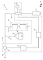
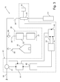
- Such a civilian and/or industrial power plant with optimized consumption 10 comprises a renewable generator 20 that is suitable for producing electric energy from renewable sources, and a plurality of electrical loads 30, 31 that are supplied by the renewable generator 20 and/or by the external network 60 and/or by the accumulation means of electric energy.
- the renewable generator 20 can be a photovoltaic generator or a wind generator and so on.
- the plurality of electrical loads 30, 31 can be the group of the apparatuses and devices connected to the electrical users of a house or of an industrial warehouse, as illustrated in figures 1 and 2 .
- the renewable generator 20 is a photovoltaic generator and comprises one or more photovoltaic panels 21 that are suitable for producing electric energy in the form of direct current, for example from 200 V to 800 V, and a DC/AC inverter 22 connected to the panels 21 themselves.
- a DC/AC inverter 22 is a device suitable for converting the direct current produced in outlet from the photovoltaic panels 21 into alternated current, for example 230 V or 400 V.
- the civilian and/or industrial power plant 10 with optimized consumption also comprises a control system 40 that is suitable for controlling at least one 31 of the plurality of electrical loads 30, 31.
- the renewable generator 20 and the plurality of electrical loads 30, 31 are connected to one another by interposition of a plurality of safety switches 35 that are suitable for automatically interrupting such connections in the case of conditions of overload or in any case of danger for the generic user.
- the at least one controlled electrical load 31 from the control system 40 is preferably a device for converting the energy suitable for converting electric energy into thermal energy, such as for example a boiler or a stove.
- the device for converting the energy is preferably provided with at least one sensor for detecting the temperature of the water or air heated by the device for converting the energy itself; the temperature sensor, in such a case, is suitable for interrupting the connection between the at least one controlled electrical load 31 and the renewable generator 20 and/or the electrical network 60 and/or the accumulation means of electric energy, if the temperature detected exceeds a predetermined temperature threshold.
- the control system 40 comprises power detection means 41, 45 suitable for detecting the difference between the instantaneous electric power generated by the renewable generator 20 and the instantaneous electric power absorbed overall by the plurality of electrical loads 30, 31.
- Such power detection means 41, 45 comprise at least one first power sensor 41, which is suitable for performing continuous detections, and a power converter 45 connected to it.
- the power converter 45 is suitable for generating a signal of amplitude that is proportional to the power detected by the sensor 41 itself.
- instantaneous power detected may be considered an average power detected over a detection period for example over a few milliseconds, where such a detection period is equal to at least the time necessary for generating the signal by the power converter 45.
- the at least one first power sensor 41 is made by means of one or three current transformers for amperometric detection and a 230 V or 400 V voltmetric socket, in the case in which the power plant 10 is respectively single phase or triple phase.
- the control system 40 moreover comprises a unit for regulating power 42, 43 programmed for or, in any case, suitable for controlling, according to a first operation modality, the electric power absorbed by at least one controlled load 31 on the basis of the detection of the power detection means 41, 45.
- the regulating unit 42, 43 carries out the aforementioned power control so that the difference between the instantaneous electric power generated by the renewable generator 20 and the instantaneous electric power absorbed overall by the plurality of electrical loads 30, 31 reaches or approaches as much as possible a first predetermined target power.
- the first predetermined target power can preferably be set by a user through first interface means (not illustrated) which are part of the control system 40 and are connected to the regulating unit 42, 43; for example the first interface means can comprise a numeric keypad.
- the power regulating unit 42, 43 comprises an automatic switch 43 controllable in voltage/current suitable for connecting in a selective way the at least one controlled electrical load 31 to the renewable generator 20 and/or to the external electrical network 60 and/or to the electric energy accumulation means.
- the automatic switch 43 is thus capable of partialising the supply voltage on the at least one controlled electrical load 31.
- the automatic switch 43 is for example of the thyristor type or of the electromechanical type.
- the signal generated by the converter 45 is preferably an analogue signal and in particular a current signal having an amplitude comprised in the range from 4 mA to 20 mA; such an amplitude is proportional to the detection by the first power sensor 41 according to a conversion scale which can be set through second interface means (not illustrated), for example a keypad, connected to the power converter 45.
- the connection between the at least one first power sensor 41 and the converter 45 is preferably cabled.
- the at least one first power sensor 41 and the converter are suitable for communicating with one another wirelessly.
- the power regulating unit 42, 43 comprises a piloting unit 42 that is connected to the power converter 45 and that is suitable for sending a control signal to the automatic switch 43 on the basis of the analogue signal generated by the converter 45 and on the first predetermined target power.
- piloting unit 42 and the automatic switch 43 provide for partializing the voltage on the at least one controlled electrical load 31 so that the power detected by the power detection means 41, 45 does not reach the first predetermined target power.
- the piloting unit 42 is moreover suitable, when initiating the power plant 10, for carrying out a self-learning procedure of the electrical characteristics of the at least one controlled load 31.
- the electrical characteristics of the controlled load 31 are stored in memory means with which the piloting unit 42 can be advantageously provided.
- the piloting unit 42 is capable of controlling the automatic switch 43 partializing the supply voltage in the most suitable manner for the electrical characteristics of the controlled load 31.
- the controlled load 31 is provided with a temperature sensor it is possible to implement a self-learning procedure of the thermal-electric characteristics of the controlled load 31 which makes it possible to track the electrical characteristics of the same with the variation of the temperature reached by the load itself.
- control system 40 also comprises a device 50 for turning it on/off connected to the automatic switch 43 so as to be able to activate and/or deactivate it.
- the turning on/off device 50 is a reset jumper for resetting the control logic of the automatic switch 43.
- Such a turning on/off device 50 can be suitable for being activated manually and/or by means of an external remote control and/or by means of a control coming from a power balancer.
- control system 40 comprises a second power sensor 63, which is suitable for performing continuous detections of the power generated by the renewable generator 20 and a first switching device 61 connected to such a second power sensor 63 and to the regulating unit 42, 43.
- the first switching device 61 is suitable for assuming a first and a second operative position, in which it allows the selective connection between the power converter 45 and respectively the first power sensor 41 or the second power sensor 63.
- the first switching device 61 is advantageously suitable for changing operative position following a manual actuation, for example by pressing a button, or following the reception of a control signal.
- a control signal can be sent by an operator by means of a remote control (not illustrated), or automatically by a thermoregulator (not illustrated) associated to the controlled load 31.
- the regulating unit 42, 43 assumes the first operation modality in which it controls the power absorbed by the controlled load 31 on the basis of the first predetermined target power as previously described.
- the regulating unit 42, 43 assumes a second operation modality in which it controls the load 31 so that the power absorbed by the same reaches or approaches as much as possible the power generated by the renewable generator 20.
- the switching device 61 ensures the so called health priority. Indeed, in such a case, when there is a demand for hot water, it is possible to dedicate all the power generated by the renewable generator 20 to the heating of the water contained in the boiler.
- the switching from the first to the second operation modality, and vice versa, of the regulating unit 42, 43 can be made by sending a control signal from the first switching device 61 to the piloting unit 42.
- the first switching device 61 can be, for example, provided with a control unit (not illustrated) which when the operative position has been changed, sends a corresponding control signal to the piloting unit 42.
- the piloting unit 42 is provided with two output lines 71, 72, as visible in figure 3 , and with a second switching device 62 connected to the first switching device 61.
- the piloting unit 42 at any input signal, sends on the first 71 and on the second 72 output line a control signal, for the automatic switch, for carrying out the first and the second operation modality, respectively.
- the second switching device 62 that switches the regulating unit 42, 43 between the first and the second operation modality; indeed, the second switching device 62 is suitable for connecting the first 71 or the second 72 output line to the automatic switch 43, respectively at the first or second operative position of the first switching device 61.
- control system 40 preferably comprises a counting device 46 that is suitable for detecting the overall power exchanged with the network itself.
- the electrical power exchanged between the power plant 10 and the external electrical network can be positive or negative according to whether at the moment of the detection the renewable generator 20 has produced too much or too little electric energy respectively with respect to the energy required by the plurality of electrical loads 30, 31. It is clear that if the exchanged electrical power is negative the owner of the power plant 10 is in debt of energy with the external electrical network 60.
- control system 40 also comprises a control unit 47 that is suitable for activating the automatic switch 43 through the turning on/off device 50, when the total electrical power exchanged with the external electrical network reaches a second predetermined target power.
- a second target power is set by the user through third interface means (not illustrated) with which the control unit 47 is preferably provided.
- the second target power is thus preferably the threshold value beyond which the user has interest in optimising the consumption of the power plant exploiting the excess energy produced by the renewable generator 20 to supply at least one controlled electrical load 31.
- the method for controlling a civilian and/or industrial power plant with optimized consumption according to the present invention is as follows.
- Such a control method comprises the operation of setting a first target power representing the difference between the instantaneous electric power generated by the renewable generator 20 and the instantaneous electric power absorbed overall by the plurality of electrical loads 30, 31 of which at least one is an electrical load 31 controlled by the control system 40.
- the first target power in particular can be positive in the case in which it is desired to use part of the electrical power produced in excess by the renewable generator 20 for supplying the controlled loads 31.
- such a first target power can be negative in the case in which the electrical power produced by the renewable generator is completely absorbed by the loads 30, 31 and it is desired to use the electrical power, coming from the external electrical network 60 and/or from the electric energy accumulation means, for supplying the controlled loads 31.
- a zero value is set for the first target power if it desired to use all the electrical power produced in excess by the renewable generator 20 for supplying the controlled loads 31.
- the electric power absorbed by the at least one controlled electrical load 31 is controlled so that the difference between the instantaneous electric power generated by the renewable generator 20 and the instantaneous electric power absorbed overall by the electrical loads 30, 31 reaches or approaches as much as possible the first set target power.
- Such a step of controlling the power is performed by activating the automatic switch 43 that is suitable for connecting in a selective way the controlled electrical load 31 to the renewable generator 20 and/or to the external electrical network 60 and/or to the electric energy accumulation means.
- the automatic switch 43 is activated according to one of the per se known piloting techniques in voltage/current, like Zero Crossing, Single Cycle, Burst Firing and Phase Angle.
- the control method comprises the operation of carrying out a procedure of self-learning the electrical and/or thermal-electric characteristics of the at least one controlled load 31.
- Such a self-learning procedure can be carried out at any time and preferably at the initiation of the civil/industrial power plant 10.
- control method advantageously comprises the operation of setting a second target power representing the value of the electrical power totally exchanged between the power plant 10 and the external electrical network 60.
- the control method After setting the value of the second target power the control method, thus, provides for the operation of detecting the electrical power totally exchanged between the power plant 10 and the external electrical network 60.
- control method provides for the deactivation of the automatic switch 43 in order to inhibit the execution of the control step of the power absorbed by the controlled load 31.
- control system makes it possible to convert the electric energy produced in excess by the renewable generator with respect to the energy needs of the electrical users connected to it into thermal energy.
- the renewable generator provides energy useful for heating the air and/or the water used in a house or in a factory.
- the control system makes it possible to regulate the use of the electric energy in excess so as to minimize the energy exchange with such an external electrical network.
- the energy produced in excess instead of being sold at rates that are disadvantageous for the owner of the renewable generator, can be used so as to satisfy in a more complete manner the energy need of the house and/or of the factory of the owner itself.
- the user therefore, has the possibility of deciding, by setting the first target power, the modality of electric energy exchange with the external electrical network.
- the first target power allows the user to set the amount of electric energy in excess to be exchanged with the network; by setting a null value for the first target power, for example, the user decides to use the total amount of energy produced in excess by the renewable generator for supplying the controlled loads.
- the second target power allows the user to set the activation conditions of the regulating unit.
- the renewable generator is a photovoltaic generator
- the electric energy required by the plurality of electrical loads is supplied only by the external electrical network.
- the electric energy supplied by the external electrical network could overall be greater than the electrical power introduced in the network itself by the power plant of which the generator is part.
- the energy exchanged between the plant and the external electrical network would be negative; by setting a positive value for the second target power the control system will activate the regulating unit only when the energy debt of the plant with respect to the external electrical network has been paid off.
- control system in addition to optimising the energy consumption of the power plant to which it is connected, makes it possible to regulate the energy exchange with the external electrical network so that the plant is not in debt of energy with respect to the network itself.
- control system and method as well as the civilian and/or industrial power plant with optimized consumption thus conceived are subject to numerous modifications and variants, all covered by the invention; moreover, all the details can be replaced by technically equivalent elements.
- materials used, as well as the dimensions, can be any according to the technical requirements.
Landscapes
- Engineering & Computer Science (AREA)
- Power Engineering (AREA)
- Supply And Distribution Of Alternating Current (AREA)
- Feedback Control In General (AREA)
Applications Claiming Priority (1)
| Application Number | Priority Date | Filing Date | Title |
|---|---|---|---|
| IT001269A ITMI20111269A1 (it) | 2011-07-07 | 2011-07-07 | Sistema e metodo di controllo per l'ottimizzazione dei consumi energetici di un impianto energetico civile e/o industriale nonche' impianto energetico civile e/o industriale a consumo ottimizzato |
Publications (2)
| Publication Number | Publication Date |
|---|---|
| EP2544324A1 true EP2544324A1 (de) | 2013-01-09 |
| EP2544324B1 EP2544324B1 (de) | 2014-04-23 |
Family
ID=44511226
Family Applications (1)
| Application Number | Title | Priority Date | Filing Date |
|---|---|---|---|
| EP12175158.0A Not-in-force EP2544324B1 (de) | 2011-07-07 | 2012-07-05 | Steuerungssystem und Verfahren zur Optimierung des Energieverbrauchs eines zivilen und/oder industriellen Kraftwerks, und ziviles und/oder industrielles Kraftwerk mit optimiertem Verbrauch |
Country Status (2)
| Country | Link |
|---|---|
| EP (1) | EP2544324B1 (de) |
| IT (1) | ITMI20111269A1 (de) |
Cited By (3)
| Publication number | Priority date | Publication date | Assignee | Title |
|---|---|---|---|---|
| US20130345891A1 (en) * | 2011-03-08 | 2013-12-26 | General Electric Company | Household energy management system |
| GB2543787A (en) * | 2015-10-27 | 2017-05-03 | Basic Holdings | A domestic controller for an energy management system |
| US20170336821A1 (en) * | 2016-05-18 | 2017-11-23 | Solarcity Corporation | Systems and methods for controlling pv production within energy export constraints |
Citations (2)
| Publication number | Priority date | Publication date | Assignee | Title |
|---|---|---|---|---|
| EP2200143A2 (de) * | 2008-12-16 | 2010-06-23 | Wittenstein AG | Verfahren zum Betreiben von elektrischen und/oder elektromechanischen Systemen |
| US20100259225A1 (en) * | 2009-04-10 | 2010-10-14 | Triune Ip Llc | Adaptive Power Control for Energy Harvesting |
-
2011
- 2011-07-07 IT IT001269A patent/ITMI20111269A1/it unknown
-
2012
- 2012-07-05 EP EP12175158.0A patent/EP2544324B1/de not_active Not-in-force
Patent Citations (2)
| Publication number | Priority date | Publication date | Assignee | Title |
|---|---|---|---|---|
| EP2200143A2 (de) * | 2008-12-16 | 2010-06-23 | Wittenstein AG | Verfahren zum Betreiben von elektrischen und/oder elektromechanischen Systemen |
| US20100259225A1 (en) * | 2009-04-10 | 2010-10-14 | Triune Ip Llc | Adaptive Power Control for Energy Harvesting |
Cited By (6)
| Publication number | Priority date | Publication date | Assignee | Title |
|---|---|---|---|---|
| US20130345891A1 (en) * | 2011-03-08 | 2013-12-26 | General Electric Company | Household energy management system |
| US9292031B2 (en) * | 2011-03-08 | 2016-03-22 | General Electric Company | Household energy management system |
| GB2543787A (en) * | 2015-10-27 | 2017-05-03 | Basic Holdings | A domestic controller for an energy management system |
| WO2017072215A1 (en) * | 2015-10-27 | 2017-05-04 | Basic Holdings | A domestic controller for an energy management system |
| US20170336821A1 (en) * | 2016-05-18 | 2017-11-23 | Solarcity Corporation | Systems and methods for controlling pv production within energy export constraints |
| US10139847B2 (en) * | 2016-05-18 | 2018-11-27 | Solarcity Corporation | Systems and methods for controlling PV production within energy export constraints |
Also Published As
| Publication number | Publication date |
|---|---|
| EP2544324B1 (de) | 2014-04-23 |
| ITMI20111269A1 (it) | 2013-01-08 |
Similar Documents
| Publication | Publication Date | Title |
|---|---|---|
| JP6203016B2 (ja) | 太陽光発電システム | |
| KR101181403B1 (ko) | 태양광 및 풍력 하이브리드 발전을 이용한 계통 연계 시스템 및 이를 이용한 태양광 및 풍력 하이브리드 계통 연계 발전 장치 | |
| AU2016100264A4 (en) | Solar Energy Capture and Storage System with Revenue Recovery through Energy Sales | |
| WO2014152893A2 (en) | Micro-grid pv system | |
| US10008951B2 (en) | System and method for coupling a monophase power source to a multiphase power network | |
| CN202813802U (zh) | 燃气热水器用智能风压系统 | |
| GB2514179A (en) | Energy store | |
| CN108475940A (zh) | 用于管理替代能量源与存储设备之间的功率流的方法和装置 | |
| EP2544324B1 (de) | Steuerungssystem und Verfahren zur Optimierung des Energieverbrauchs eines zivilen und/oder industriellen Kraftwerks, und ziviles und/oder industrielles Kraftwerk mit optimiertem Verbrauch | |
| JP6199804B2 (ja) | 電力制御システム、電力制御システムの制御方法、及び電力制御装置 | |
| WO2004100337A1 (ja) | 系統連系インバータを含む電源装置 | |
| US10523006B2 (en) | Controller for an inverter | |
| CN209562512U (zh) | 一种光伏系统和检测系统 | |
| CZ304509B6 (cs) | Systém pro hospodaření s elektrickou energií vyrobenou fotovoltaickými články | |
| JP2016135009A (ja) | 電力供給システム | |
| CN219797329U (zh) | 一种基于交流电使用的太阳能供暖系统 | |
| JP6762297B2 (ja) | 機器制御システムおよび制御方法 | |
| CN203704140U (zh) | 集中分布式智能采暖系统 | |
| RU2846008C1 (ru) | Система распределения потребления электрической энергии | |
| JP6258774B2 (ja) | 電力制御システム、電力制御装置、および電力制御システムの制御方法 | |
| CN217010745U (zh) | 光伏储能集成系统 | |
| CN202126639U (zh) | 一种风机部件加热设备 | |
| Aliya et al. | A Novel Algorithm for Intelligent Home Energy Management System | |
| CN108321835A (zh) | 四象限并网型微电网逆流控制器 | |
| Trzmiel et al. | The use of the SCADA system in the monitoring and control of the performance of an autonomous hybrid power supply system using renewable energy sources |
Legal Events
| Date | Code | Title | Description |
|---|---|---|---|
| PUAI | Public reference made under article 153(3) epc to a published international application that has entered the european phase |
Free format text: ORIGINAL CODE: 0009012 |
|
| AK | Designated contracting states |
Kind code of ref document: A1 Designated state(s): AL AT BE BG CH CY CZ DE DK EE ES FI FR GB GR HR HU IE IS IT LI LT LU LV MC MK MT NL NO PL PT RO RS SE SI SK SM TR |
|
| AX | Request for extension of the european patent |
Extension state: BA ME |
|
| 17P | Request for examination filed |
Effective date: 20130705 |
|
| RBV | Designated contracting states (corrected) |
Designated state(s): AL AT BE BG CH CY CZ DE DK EE ES FI FR GB GR HR HU IE IS IT LI LT LU LV MC MK MT NL NO PL PT RO RS SE SI SK SM TR |
|
| GRAP | Despatch of communication of intention to grant a patent |
Free format text: ORIGINAL CODE: EPIDOSNIGR1 |
|
| RIC1 | Information provided on ipc code assigned before grant |
Ipc: H02J 1/00 20060101ALI20131024BHEP Ipc: H02J 1/14 20060101AFI20131024BHEP |
|
| INTG | Intention to grant announced |
Effective date: 20131125 |
|
| GRAS | Grant fee paid |
Free format text: ORIGINAL CODE: EPIDOSNIGR3 |
|
| GRAA | (expected) grant |
Free format text: ORIGINAL CODE: 0009210 |
|
| AK | Designated contracting states |
Kind code of ref document: B1 Designated state(s): AL AT BE BG CH CY CZ DE DK EE ES FI FR GB GR HR HU IE IS IT LI LT LU LV MC MK MT NL NO PL PT RO RS SE SI SK SM TR |
|
| REG | Reference to a national code |
Ref country code: GB Ref legal event code: FG4D |
|
| REG | Reference to a national code |
Ref country code: CH Ref legal event code: EP |
|
| REG | Reference to a national code |
Ref country code: AT Ref legal event code: REF Ref document number: 664331 Country of ref document: AT Kind code of ref document: T Effective date: 20140515 |
|
| REG | Reference to a national code |
Ref country code: IE Ref legal event code: FG4D |
|
| REG | Reference to a national code |
Ref country code: DE Ref legal event code: R096 Ref document number: 602012001473 Country of ref document: DE Effective date: 20140612 |
|
| REG | Reference to a national code |
Ref country code: AT Ref legal event code: MK05 Ref document number: 664331 Country of ref document: AT Kind code of ref document: T Effective date: 20140423 |
|
| REG | Reference to a national code |
Ref country code: NL Ref legal event code: VDEP Effective date: 20140423 |
|
| REG | Reference to a national code |
Ref country code: LT Ref legal event code: MG4D |
|
| PG25 | Lapsed in a contracting state [announced via postgrant information from national office to epo] |
Ref country code: IS Free format text: LAPSE BECAUSE OF FAILURE TO SUBMIT A TRANSLATION OF THE DESCRIPTION OR TO PAY THE FEE WITHIN THE PRESCRIBED TIME-LIMIT Effective date: 20140823 Ref country code: NL Free format text: LAPSE BECAUSE OF FAILURE TO SUBMIT A TRANSLATION OF THE DESCRIPTION OR TO PAY THE FEE WITHIN THE PRESCRIBED TIME-LIMIT Effective date: 20140423 Ref country code: CY Free format text: LAPSE BECAUSE OF FAILURE TO SUBMIT A TRANSLATION OF THE DESCRIPTION OR TO PAY THE FEE WITHIN THE PRESCRIBED TIME-LIMIT Effective date: 20140423 Ref country code: LT Free format text: LAPSE BECAUSE OF FAILURE TO SUBMIT A TRANSLATION OF THE DESCRIPTION OR TO PAY THE FEE WITHIN THE PRESCRIBED TIME-LIMIT Effective date: 20140423 Ref country code: BG Free format text: LAPSE BECAUSE OF FAILURE TO SUBMIT A TRANSLATION OF THE DESCRIPTION OR TO PAY THE FEE WITHIN THE PRESCRIBED TIME-LIMIT Effective date: 20140723 Ref country code: FI Free format text: LAPSE BECAUSE OF FAILURE TO SUBMIT A TRANSLATION OF THE DESCRIPTION OR TO PAY THE FEE WITHIN THE PRESCRIBED TIME-LIMIT Effective date: 20140423 Ref country code: NO Free format text: LAPSE BECAUSE OF FAILURE TO SUBMIT A TRANSLATION OF THE DESCRIPTION OR TO PAY THE FEE WITHIN THE PRESCRIBED TIME-LIMIT Effective date: 20140723 Ref country code: GR Free format text: LAPSE BECAUSE OF FAILURE TO SUBMIT A TRANSLATION OF THE DESCRIPTION OR TO PAY THE FEE WITHIN THE PRESCRIBED TIME-LIMIT Effective date: 20140724 |
|
| PG25 | Lapsed in a contracting state [announced via postgrant information from national office to epo] |
Ref country code: SE Free format text: LAPSE BECAUSE OF FAILURE TO SUBMIT A TRANSLATION OF THE DESCRIPTION OR TO PAY THE FEE WITHIN THE PRESCRIBED TIME-LIMIT Effective date: 20140423 Ref country code: HR Free format text: LAPSE BECAUSE OF FAILURE TO SUBMIT A TRANSLATION OF THE DESCRIPTION OR TO PAY THE FEE WITHIN THE PRESCRIBED TIME-LIMIT Effective date: 20140423 Ref country code: AT Free format text: LAPSE BECAUSE OF FAILURE TO SUBMIT A TRANSLATION OF THE DESCRIPTION OR TO PAY THE FEE WITHIN THE PRESCRIBED TIME-LIMIT Effective date: 20140423 Ref country code: RS Free format text: LAPSE BECAUSE OF FAILURE TO SUBMIT A TRANSLATION OF THE DESCRIPTION OR TO PAY THE FEE WITHIN THE PRESCRIBED TIME-LIMIT Effective date: 20140423 Ref country code: LV Free format text: LAPSE BECAUSE OF FAILURE TO SUBMIT A TRANSLATION OF THE DESCRIPTION OR TO PAY THE FEE WITHIN THE PRESCRIBED TIME-LIMIT Effective date: 20140423 Ref country code: ES Free format text: LAPSE BECAUSE OF FAILURE TO SUBMIT A TRANSLATION OF THE DESCRIPTION OR TO PAY THE FEE WITHIN THE PRESCRIBED TIME-LIMIT Effective date: 20140423 Ref country code: PL Free format text: LAPSE BECAUSE OF FAILURE TO SUBMIT A TRANSLATION OF THE DESCRIPTION OR TO PAY THE FEE WITHIN THE PRESCRIBED TIME-LIMIT Effective date: 20140423 |
|
| PG25 | Lapsed in a contracting state [announced via postgrant information from national office to epo] |
Ref country code: PT Free format text: LAPSE BECAUSE OF FAILURE TO SUBMIT A TRANSLATION OF THE DESCRIPTION OR TO PAY THE FEE WITHIN THE PRESCRIBED TIME-LIMIT Effective date: 20140825 |
|
| REG | Reference to a national code |
Ref country code: DE Ref legal event code: R097 Ref document number: 602012001473 Country of ref document: DE |
|
| PG25 | Lapsed in a contracting state [announced via postgrant information from national office to epo] |
Ref country code: RO Free format text: LAPSE BECAUSE OF FAILURE TO SUBMIT A TRANSLATION OF THE DESCRIPTION OR TO PAY THE FEE WITHIN THE PRESCRIBED TIME-LIMIT Effective date: 20140423 Ref country code: EE Free format text: LAPSE BECAUSE OF FAILURE TO SUBMIT A TRANSLATION OF THE DESCRIPTION OR TO PAY THE FEE WITHIN THE PRESCRIBED TIME-LIMIT Effective date: 20140423 Ref country code: SK Free format text: LAPSE BECAUSE OF FAILURE TO SUBMIT A TRANSLATION OF THE DESCRIPTION OR TO PAY THE FEE WITHIN THE PRESCRIBED TIME-LIMIT Effective date: 20140423 Ref country code: CZ Free format text: LAPSE BECAUSE OF FAILURE TO SUBMIT A TRANSLATION OF THE DESCRIPTION OR TO PAY THE FEE WITHIN THE PRESCRIBED TIME-LIMIT Effective date: 20140423 Ref country code: BE Free format text: LAPSE BECAUSE OF FAILURE TO SUBMIT A TRANSLATION OF THE DESCRIPTION OR TO PAY THE FEE WITHIN THE PRESCRIBED TIME-LIMIT Effective date: 20140423 Ref country code: DK Free format text: LAPSE BECAUSE OF FAILURE TO SUBMIT A TRANSLATION OF THE DESCRIPTION OR TO PAY THE FEE WITHIN THE PRESCRIBED TIME-LIMIT Effective date: 20140423 |
|
| PGFP | Annual fee paid to national office [announced via postgrant information from national office to epo] |
Ref country code: DE Payment date: 20140929 Year of fee payment: 3 |
|
| PG25 | Lapsed in a contracting state [announced via postgrant information from national office to epo] |
Ref country code: LU Free format text: LAPSE BECAUSE OF FAILURE TO SUBMIT A TRANSLATION OF THE DESCRIPTION OR TO PAY THE FEE WITHIN THE PRESCRIBED TIME-LIMIT Effective date: 20140705 |
|
| PLBE | No opposition filed within time limit |
Free format text: ORIGINAL CODE: 0009261 |
|
| STAA | Information on the status of an ep patent application or granted ep patent |
Free format text: STATUS: NO OPPOSITION FILED WITHIN TIME LIMIT |
|
| 26N | No opposition filed |
Effective date: 20150126 |
|
| REG | Reference to a national code |
Ref country code: IE Ref legal event code: MM4A |
|
| REG | Reference to a national code |
Ref country code: FR Ref legal event code: ST Effective date: 20150331 |
|
| REG | Reference to a national code |
Ref country code: DE Ref legal event code: R097 Ref document number: 602012001473 Country of ref document: DE Effective date: 20150126 |
|
| PG25 | Lapsed in a contracting state [announced via postgrant information from national office to epo] |
Ref country code: FR Free format text: LAPSE BECAUSE OF NON-PAYMENT OF DUE FEES Effective date: 20140731 |
|
| PG25 | Lapsed in a contracting state [announced via postgrant information from national office to epo] |
Ref country code: SI Free format text: LAPSE BECAUSE OF FAILURE TO SUBMIT A TRANSLATION OF THE DESCRIPTION OR TO PAY THE FEE WITHIN THE PRESCRIBED TIME-LIMIT Effective date: 20140423 |
|
| PG25 | Lapsed in a contracting state [announced via postgrant information from national office to epo] |
Ref country code: IE Free format text: LAPSE BECAUSE OF NON-PAYMENT OF DUE FEES Effective date: 20140705 |
|
| REG | Reference to a national code |
Ref country code: DE Ref legal event code: R119 Ref document number: 602012001473 Country of ref document: DE |
|
| REG | Reference to a national code |
Ref country code: CH Ref legal event code: PL |
|
| PG25 | Lapsed in a contracting state [announced via postgrant information from national office to epo] |
Ref country code: DE Free format text: LAPSE BECAUSE OF NON-PAYMENT OF DUE FEES Effective date: 20160202 Ref country code: LI Free format text: LAPSE BECAUSE OF NON-PAYMENT OF DUE FEES Effective date: 20150731 Ref country code: SM Free format text: LAPSE BECAUSE OF FAILURE TO SUBMIT A TRANSLATION OF THE DESCRIPTION OR TO PAY THE FEE WITHIN THE PRESCRIBED TIME-LIMIT Effective date: 20140423 Ref country code: MC Free format text: LAPSE BECAUSE OF FAILURE TO SUBMIT A TRANSLATION OF THE DESCRIPTION OR TO PAY THE FEE WITHIN THE PRESCRIBED TIME-LIMIT Effective date: 20140423 Ref country code: CH Free format text: LAPSE BECAUSE OF NON-PAYMENT OF DUE FEES Effective date: 20150731 |
|
| PG25 | Lapsed in a contracting state [announced via postgrant information from national office to epo] |
Ref country code: MT Free format text: LAPSE BECAUSE OF FAILURE TO SUBMIT A TRANSLATION OF THE DESCRIPTION OR TO PAY THE FEE WITHIN THE PRESCRIBED TIME-LIMIT Effective date: 20140423 |
|
| PG25 | Lapsed in a contracting state [announced via postgrant information from national office to epo] |
Ref country code: HU Free format text: LAPSE BECAUSE OF FAILURE TO SUBMIT A TRANSLATION OF THE DESCRIPTION OR TO PAY THE FEE WITHIN THE PRESCRIBED TIME-LIMIT; INVALID AB INITIO Effective date: 20120705 Ref country code: TR Free format text: LAPSE BECAUSE OF FAILURE TO SUBMIT A TRANSLATION OF THE DESCRIPTION OR TO PAY THE FEE WITHIN THE PRESCRIBED TIME-LIMIT Effective date: 20140423 |
|
| GBPC | Gb: european patent ceased through non-payment of renewal fee |
Effective date: 20160705 |
|
| PG25 | Lapsed in a contracting state [announced via postgrant information from national office to epo] |
Ref country code: GB Free format text: LAPSE BECAUSE OF NON-PAYMENT OF DUE FEES Effective date: 20160705 |
|
| PG25 | Lapsed in a contracting state [announced via postgrant information from national office to epo] |
Ref country code: MK Free format text: LAPSE BECAUSE OF FAILURE TO SUBMIT A TRANSLATION OF THE DESCRIPTION OR TO PAY THE FEE WITHIN THE PRESCRIBED TIME-LIMIT Effective date: 20140423 |
|
| PG25 | Lapsed in a contracting state [announced via postgrant information from national office to epo] |
Ref country code: AL Free format text: LAPSE BECAUSE OF FAILURE TO SUBMIT A TRANSLATION OF THE DESCRIPTION OR TO PAY THE FEE WITHIN THE PRESCRIBED TIME-LIMIT Effective date: 20140423 |
|
| PGFP | Annual fee paid to national office [announced via postgrant information from national office to epo] |
Ref country code: IT Payment date: 20180628 Year of fee payment: 7 |
|
| PG25 | Lapsed in a contracting state [announced via postgrant information from national office to epo] |
Ref country code: IT Free format text: LAPSE BECAUSE OF NON-PAYMENT OF DUE FEES Effective date: 20190705 |