EP2544519B1 - Boîtes de vitesses à commande automatique pour un outil avec flèche d'attelage pivotante - Google Patents
Boîtes de vitesses à commande automatique pour un outil avec flèche d'attelage pivotante Download PDFInfo
- Publication number
- EP2544519B1 EP2544519B1 EP11719873.9A EP11719873A EP2544519B1 EP 2544519 B1 EP2544519 B1 EP 2544519B1 EP 11719873 A EP11719873 A EP 11719873A EP 2544519 B1 EP2544519 B1 EP 2544519B1
- Authority
- EP
- European Patent Office
- Prior art keywords
- gearbox
- rotary
- frame
- output shaft
- attached
- Prior art date
- Legal status (The legal status is an assumption and is not a legal conclusion. Google has not performed a legal analysis and makes no representation as to the accuracy of the status listed.)
- Ceased
Links
- 238000000034 method Methods 0.000 claims 1
- 230000000295 complement effect Effects 0.000 description 3
- 241001124569 Lycaenidae Species 0.000 description 2
- 230000000712 assembly Effects 0.000 description 2
- 238000000429 assembly Methods 0.000 description 2
- 230000003750 conditioning effect Effects 0.000 description 2
- 238000003306 harvesting Methods 0.000 description 2
- 238000012986 modification Methods 0.000 description 2
- 230000004048 modification Effects 0.000 description 2
- 230000002411 adverse Effects 0.000 description 1
- 238000010276 construction Methods 0.000 description 1
- 238000004904 shortening Methods 0.000 description 1
- 238000009987 spinning Methods 0.000 description 1
Images





Classifications
-
- A—HUMAN NECESSITIES
- A01—AGRICULTURE; FORESTRY; ANIMAL HUSBANDRY; HUNTING; TRAPPING; FISHING
- A01D—HARVESTING; MOWING
- A01D34/00—Mowers; Mowing apparatus of harvesters
- A01D34/01—Mowers; Mowing apparatus of harvesters characterised by features relating to the type of cutting apparatus
- A01D34/412—Mowers; Mowing apparatus of harvesters characterised by features relating to the type of cutting apparatus having rotating cutters
- A01D34/63—Mowers; Mowing apparatus of harvesters characterised by features relating to the type of cutting apparatus having rotating cutters having cutters rotating about a vertical axis
- A01D34/64—Mowers; Mowing apparatus of harvesters characterised by features relating to the type of cutting apparatus having rotating cutters having cutters rotating about a vertical axis mounted on a vehicle, e.g. a tractor, or drawn by an animal or a vehicle
- A01D34/66—Mowers; Mowing apparatus of harvesters characterised by features relating to the type of cutting apparatus having rotating cutters having cutters rotating about a vertical axis mounted on a vehicle, e.g. a tractor, or drawn by an animal or a vehicle with two or more cutters
- A01D34/661—Mounting means
-
- A—HUMAN NECESSITIES
- A01—AGRICULTURE; FORESTRY; ANIMAL HUSBANDRY; HUNTING; TRAPPING; FISHING
- A01D—HARVESTING; MOWING
- A01D67/00—Undercarriages or frames specially adapted for harvesters or mowers; Mechanisms for adjusting the frame; Platforms
- A01D67/005—Arrangements of coupling devices
Definitions
- the present invention relates to crop harvesting equipment and, more particularly, to pull-type mowers or mower/conditioners having a pulling tongue which is hydraulically swingable from side-to-side so that the lateral position of the machine relative to the towing tractor can be adjusted on-the-go from the tractor seat. More particularly, the present invention involves a swing tongue harvester of the aforementioned type wherein provision is made for driving the operating components of the harvesting header, such as the crop severing mechanism and the conditioner rolls, through mechanical structures coupled with the power takeoff shaft of the towing vehicle, rather than through a hydraulic drive system.
- Swing-tongue harvesters have become extremely popular over the years due in part to their ability to be quickly and easily maneuvered from the tractor seat around obstacles, through right angle turns, and otherwise operated in a manner previously reserved only for self-propelled vehicles.
- the machine In the case of swing-tongue harvesters in which the tongue is pivoted about the frame, the machine is capable of being used to be positioned in an operative position behind a towing tractor to one side of the tractor when the mower is being used to cut a crop and a transport position wherein the machine is behind the towing tractor for transporting the machine from place to place.
- having a pulling tongue which is shifted between relatively sharp angular positions creates problems in the delivery of driving power from the tractor to operating components of the machine.
- a pulled mower of the fore-mentioned type is known from European patent application EP 2 055 169 A1 .
- EP 2 055 169 A1 discloses a an implement comprising frame, a tongue having a front end, a back end and having a hitch point at the front end thereof and being operatively pivotally connected to the frame at the back end thereof.
- the implement comprises an implement that is operatively attached to the frame, and a first gearbox having an input shaft and an output shaft.
- EP'169 further discloses a second gearbox having an input shaft that is operatively attached to the output shaft of the first gearbox.
- the second gearbox has an output shaft.
- the known implement further comprises a third gearbox having an input shaft and an output shaft, the output shaft of the third gearbox being disposed for rotation about an axis, the third gearbox being operatively pivotally mounted to the implement about the axis of rotation of the output shaft of the third gearbox.
- EP'169 discloses a variable length driveline assembly that is operatively attached to the output shaft of the second gearbox at one end thereof and operatively attached to the input shaft of the third gearbox at the other end thereof.
- the present invention relates to a mowing and/or conditioning machine with pivoting steered gearboxes.
- the design contemplated in Figs. 1-16 provides a mower conditioner having a header that is suspended from a frame and includes a plurality of cutting blades laterally disposed relative to the ground and conditioning rollers at the
- the mower includes a tongue connecting the mower to a towing unit.
- the tongue is pivotally connected to the mower frame.
- At the front portion of the tongue is an upper tongue swivel gearbox, gearbox one, rigidly attached to the tongue which transmits rotary power from the power take off of the tractor to a lower tongue swivel gearbox, gearbox two, located directly below and pivotally attached to gearbox one.
- Gearbox two is attached to the front end of a telescoping driveline that is attached, at its rear end, to the input shaft of a rear gearbox, gearbox three.
- the output shaft of gear box three is connected a drive shaft that is attached to the rotary cutting units.
- Gearbox three is mounted to the mower frame, beneath and at the rear of the tongue, with a pivoting arrangement, so that the gearbox housing and input shaft can pivot about the axis of its output shaft.
- the pivoting rear gearbox three is attached to the header frame with the input shat connected at a U-joint to the output end of a telescopic drive line section.
- the other end of the telescopic drive line section is connected at another U-joint located forward from the mower header along and below the tongue.
- the telescopic drive line section connects with a gearbox two that is connected to the gearbox one above gearbox two.
- Gearbox one is connected to a forward section of drive line that is operatively connected to the power takeoff of the tractor.
- telescoping steering cylinders also extending around the telescoping drive line and between the U-joints located between the pivoting gearbox two and the pivoting gearbox three are telescoping steering cylinders. These telescoping cylinders also serve as a guard to keep operators from becoming tangled in the driven shaft which extends between the two aforementioned U-joints. As shown in the drawings, the telescoping steering cylinders attach at one end to the U-joint adjacent the pivoting rear gear box structure three and at the opposite end to the U-joint on the other (front) end of the drive line connection, where it connects to forward lower gearbox two.
- a second embodiment shown in Figs. 13-15 has a pivoting rear gearbox on the header as a simple right angle gearbox that pivots along a vertical axis and is steered by a front gearbox that is operatively fixed to the tongue.
- a primary advantage to both concepts is to minimize the u-joint angles in the drive system.
- a third embodiment shown in Fig 16 utilizes the driveline arrangement of the first embodiment, with a different configuration of the tongue and mower header, in a center pivot arrangement, where the tongue is connected to the middle of the machine, and the mower is able to swing off to either side, to mow on either side of the towing unit.
- One aspect of the present invention is the arrangement of the tongue and the driveline with a swivel gear box assembly, the combination of gearboxes one and two, mounted at the front portion of the tongue. This combination allows the towing forces to remain contained in the tongue, not transferred through the gearboxes, while providing a driveline with the capability of allowing various angles of operation.
- FIG. 1 shows a mower (10) with automatically steered gearboxes including a frame (11) with wheels (12) operatively attached thereto for permitting the frame (11) to be towed from place to place.
- a header (13) is operatively attached to the frame (11) by top links (14) and bottom links (15) for example in the way shown in U.S. Patent No. 7,726,109 in Figs. 8-12b .
- Hydraulic cylinders (16) attached to the frame (11) and the header (13) in the way disclosed in U.S. Patent No. 7,726,109 are used to raise or lower the header (13) with respect to the frame (11) for example between the raised position shown in Fig. 4 and the lowered position shown in Fig. 5 .
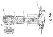
- Cutters (17) are operatively rotatably attached to the header (13) in the way shown in Figs. 5a and 5c for cutting plants off a short distance above the ground.
- a tongue (21) is operatively pivotally attached along a first substantially vertical axis c as shown in Fig 5 by a bracket (22) and pin (23) to the frame (11) at one end thereof and adapted to be attached to a prime mover (1) at the other end thereof by use of a hitch (24) ;
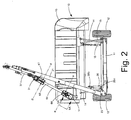
- a hydraulic actuator (16) is operatively attached to the frame (11) and is operatively attached to the tongue (21) for adjusting an angle of the tongue (21) along the first substantially vertical axis c with respect to the frame (11) between (i) an operating position (see Fig. 3 ), whereby the wheels of the prime mover (1) are to one side of the cutters (17) as the mower (10) is towed through a field in a forward direction so that the wheels of the towing prime mover (1) do not pass over the crop being cut by the cutters (17) as the mower (10) is being used to cut crops, and (ii) a transport position (see Figs. 1 and 2 ) whereby the angle of the tongue (21) with respect to the frame (11) is such that the wheels of the prime mover are in front of the cutters (17) .
- a first gearbox (31) is operatively rigidly attached to the tongue (21) by use of a bracket (32) with portions (32t) and (32b) on the top and the bottom of the tongue (21) as can best be seen in Figs. 8- 11 .
- the first gearbox (31) has a rotary input shaft (33) best seen in Figs. 8 and 12 , adapted to be attached to a power take off (35) of the prime mover (1) , as shown in Fig. 1 , and a rotary output shaft (36) as shown in Fig. 12 rotatable about a second substantially vertical axis a , shown in Fig.
- the driveline includes a CV joint on the end that attaches to the PTO shaft of the towing unit, and a standard universal joint on the end that attaches to the first gearbox.
- the rotary power is transferred from the PTO shaft of the towing unit (35) to the input shaft (33) and then transmitted by the first gearbox (31) to the rotary output shaft (36) of the first gearbox (31) .
- the housing of the first gearbox (31) is rigidly mounted to the tongue (21) at the front portion of the tongue such that it is a proper distance from the hitch point.
- a second gearbox (41) is operatively pivotally attached to the first gearbox (31) about the second substantially vertical axis a, the second gearbox (41) has a rotary input shaft (46) which can be in one piece with rotary output shaft (36) of the first gearbox (31) or rotary input shaft (46) and rotary output shaft (36) can be separate shafts connected together, it being noted that claiming these shafts separately is meant to include inter alia a one or two piece shaft construction between gearboxes (31) and (41) . Whether shafts (36) and (37) are connected together later or manufactured in one piece at the outset is clearly equivalent.
- the rotary input shaft (46) of the second gearbox (41) is operatively attached to the rotary output shaft (36) of the first gearbox (31) thereby transmitting rotary power from the rotary output shaft (36) of the first gearbox (31) to the rotary input shaft (36) of the second gearbox (41) for causing the rotary output shaft (43) of the second gearbox ( 41 ) to rotate.
- a third gearbox (51) is operatively pivotally attached to the header (13) about a third substantially vertical axis b as shown in Fig. 5 , the third gearbox (51) having a rotary input shaft (53) and a rotary output shaft (56) , the rotary output shaft (56) being operatively attached to the cutters (17) through double universal joint (57) for causing the cutters (17) to move in a cutting manner, which is a rotary motion in the embodiment shown.
- Figs. 5 A third gearbox (51) is operatively pivotally attached to the header (13) about a third substantially vertical axis b as shown in Fig. 5 , the third gearbox (51) having a rotary input shaft (53) and a rotary output shaft (56) , the rotary output shaft (56) being operatively attached to the cutters (17) through double universal joint (57) for causing the cutters (17) to move in a cutting manner, which is a rotary motion in the embodiment shown.
- a double universal joint (57) connects the output shaft (56) of the third gearbox (51) to the input shaft (58) of the cutter bar (17) , which cutter bar structure can be of any one of many well known cutter bars which do not form part of this invention per se.
- a first universal joint (61) is operatively attached to the rotary output shaft (43) of the second gearbox (41) .
- a telescoping driveline (62) comprising an outer sleeve (62a) and a complementary shaped inner shaft (62b) , is operatively attached to the first universal joint (61) at a front end thereof.
- the sleeve (62a) could be square in cross section and the shaft (62b) square in cross section so the shaft (62b) can slid in or out in the sleeve (62a) to permit the two parts to transmit rotary power while also being able to automatically adjust the length thereof as needed.
- Extending around the telescoping driveline (62) is a gearbox steering device which in a preferred embodiment includes two telescoping tubes (64) and (65) which serve two purposes.
- the two telescoping tubes (64) and (65) serve to steer the second and third gear boxes (41) and (51) as the tongue (21) pivots with respect to the frame (11) .
- the two telescoping tubes (64) and (65) serve as a safety shield to help prevent anything, such as clothing, from wrapping around the driveshaft parts (62a) and (62b) as they rotate.
- the two telescoping tubes (64) and (65) are preferably round in cross section as is typical for guards that encompass drive shafts in agricultural equipment.
- tube (64) and (65) do not rotate, tube (64) being bolted along a horizontal pivotal axis (e) to bracket (71) that is connected rigidly to the bracket surrounding gearbox three (51) .
- tube (65) is bolted along a horizontal pivotal axis (d) to bracket (72) which is rigidly attached to gearbox two (32) .
- the telescoping drive line (62) at the rear end thereof, is connected to a second universal joint (66) and to the rotary input shaft (53) of the third gearbox (51) whereby rotary power from the rotary output shaft (43) of the second gearbox (41) will be transmitted through the first universal joint (61) , the telescoping driveline (62) , the second universal joint (66) , the rotary input shaft (53) of the third gearbox (51) to the output shaft (56) of the third gearbox (51) to cause the cutting movement of the cutters (17) .
- Drive shaft 37 shown in Fig. 6 , dimension D is a minimum of 66,2 cm (thirty (30) inches).
- the advantage of using a longer driveline than those used in the prior art for the present invention is that the angles that the joints are subjected to are reduced, as compared to shorter drivelines. With this minimum length of 66,2 cm (30 inches) it is known that a front CV is capable of withstanding those angles. If a shorter driveline were to be used, the durability of the CV would be adversely affected.
- the mower/conditioner (10) can be towed from place to place, including on public roads, because a hydraulic cylinder (20) pivotally attached to the frame ( 11 ) along a vertical axis (20a) and to the tongue (21) at vertical axis (20b) is shortened to pull the tongue (21) to the transport position shown in Fig. 1 .
- the second and third gearboxes ( 41 and 51 ) will pivot along vertical axes (a) and (b) respectively.
- the input/output shafts and associated unnumbered gears shown in Figs. 5a , 5c and 12 accommodate such pivoting along vertical axes (a) and (b) .
- the header (13) would also be raised to the position shown in Fig. 4 by lengthening the hydraulic cylinders (16) to pivot upper and lower links (14) and (15) .
- hydraulic cylinder (20) is lengthened to the position shown in Fig. 3 so that the towing vehicle's tires are to the left of the crop in front of the mower/conditioner (10) so the tires of the towing vehicle (1) will not smash down the crop and make it difficult to cut.
- the header (13) would also be lowered to the position shown in Fig. 5 by shortening the hydraulic cylinders (16) to pivot upper and lower links (14) and (15) .
- the second and third gearboxes (31) and (41) are automatically moved or steered up/down/left/right when all of this adjusting between a transport position and an operation position is done.
- the front gearboxes (31) and (41) of the Figs. 1-12 embodiment are replaced with a normal increaser front gearbox (131) with an input shaft (133) for attachment to the drive shaft (37) via au-joint as in Fig. 1 , the input shaft (133) being disposed along a rotational axis (f) and an output shaft (136) that is disposed along a rotational axis (g) that is preferably parallel to the rotational axis (f) but is not required to be parallel to the axis (f) .
- spherical ball joint (166) is attached to the front gearbox (131) instead of using the telescoping steering members (64) and (65) shown in Figs. 1-7 .
- This can optionally eliminate the need for a CV u-joint for the rear gearbox (51) and the front one (61) is not as critical so a standard u-joint could be used there.
- the same telescoping drive linkage (62) including receiver (62a) having complementary shaft (62b) extending therein as shown in Fig. 5b would be used but without the telescoping steering tubes (64) and (65) which have been replaced by telescoping steering tubes (164) and (165) .
- the rear end of steering tube (65) has a bracket (167) rigidly attached thereto, which bracket (167) is pivotally attached along a substantially horizontal axis (h) to the housing of gearbox (51) .
- Gearbox (51) still pivots about vertical axis (c) as shown in Fig. 6 , for example, using the same structure shown in Figs. 5a and 5c , for example.
- the solid line structure of the second embodiment shown in Fig. 13 can be placed into the mower of Figs. 1-5 and 6-11 to replace all of the gearboxes 31, 41 and 51 and the structure connecting gearboxes 41 and 51 and such the solid line structure of Fig. 13 is hereby incorporated into Figs. 1-11 by reference.
- Fig. 15 shows that the telescoping drive shaft (62) is square in cross section, but it could be of any cross sectional shape that is not circular, such as using a splined shaft (62b) that would extend into a complementary shaped opening in shaft (62a).
- Fig. 16 shows a mower (210) with a header (213) configured to operate when positioned to either the right side, or the left side of a towing vehicle.
- a header (213) is operatively attached to the frame (11) by top links (14) and bottom links (15) for example in the way shown in U.S. Patent No. 7,726,109 in Figs. 8-12b .
- the mower can be positioned by rotating tongue (221) about the axis of pin (223).
- the rotational drive for the mower is transferred from the towing vehicle to the mower using the automatically steered gearboxes of the present invention including a front swivel gear box assembly (212) and a rear gearbox (251).
- the front swivel gearbox assembly (212) is comprised of an upper gearbox (31) and a lower gearbox (41), as shown in greater detail in Fig. 12 .
- Gearbox (31) is located at a distance from the hitch (24), mounted directly to the tongue (21), and positioned such that the first shaft assembly (37) is a minimum length of 30 inches.
- This shaft which is also known as a driveline, is a variable length member, configured to allow variation of the distance and relative angles between the power take off (PTO) shaft of the towing vehicle and the input shaft (33) of the first gearbox. These variations occur as the machine is towed over variations in the terrain and around corners.
- a standard CV joint (214) can be used at the front of the shaft (37), where the shaft connects to the PTO shaft of the towing vehicle.
- the rear of the shaft (37) is connected to the input shaft (33) of gearbox (31) with a U-joint. While CV joints are preferred where mentioned in this document, regular U-joints can be used instead and are considered fully equivalent structures.
- the housing of the upper gearbox is oriented so that the axis of the input shaft (33) is approximately parallel to the axis of the driveline (37) in the top view of Fig. 16 , with the mower positioned directly behind the towing vehicle.
- the driveline and input shaft will be repositioned into a non-parallel relationship, and so will have an angular offset.
- the angular offset is determined by the length of the shaft (37), which is set by the position of the gearbox (212), the length of the tongue (221), and the width of the mower.
- the angular offset if kept to an acceptable maximum, will not affect the performance of the machine, and a standard U-joint will be capable of providing acceptable performance. If the angular offset is too large for a standard U-Joint, then a second CV joint could be used in place of the U-joint.
- the rest of the drive is the same as described in the other embodiments, with the rotary power transferred through the swivel gearbox (212), from gearbox (31), to gearbox (41), then to the first universal joint (61) of the telescoping driveline (62), then to the second universal joint (66) which is attached to the input shaft (53) of gearbox (251).
- the steerable gearboxes of the present invention can be configured for use with a mower that can operate while swung to either the left or the right side.
Landscapes
- Life Sciences & Earth Sciences (AREA)
- Environmental Sciences (AREA)
- Harvester Elements (AREA)
- Agricultural Machines (AREA)
Claims (20)
- Machine agricole comprenant :a. un châssis (11) ;b. une flèche d'attelage (21) ayant une extrémité avant, une extrémité arrière et ayant un point d'attelage (24) à l'extrémité avant de celle-ci et étant rattachée de manière opérationnelle et pivotante au châssis (11) à l'extrémité arrière de celle-ci ;c. une machine agricole (1) attachée de manière opérationnelle au châssis (11) ;d. une première boîte d'embrayages (31) ayant un arbre d'entrée (34) et un arbre de sortie (36) ;e. une deuxième boîte d'engrenages (41) ayant un arbre d'entrée (46) attaché de manière opérationnelle à l'arbre de sortie (36) de la première boîte d'engrenages (31), cette deuxième boîte d'engrenages ayant un arbre de sortie (43) ; etf. une troisième boîte d'engrenages (51) ayant un arbre d'entrée (53) et un arbre de sortie (56), l'arbre de sortie de cette troisième boîte d'engrenages étant disposé de façon à tourner autour d'un axe, cette troisième boîte d'engrenages étant montée de manière opérationnelle et pivotante sur la machine agricole autour de l'axe de rotation de l'arbre de sortie de la troisième boîte d'engrenages ;g. un ensemble chaîne cinématique de longueur variable (37) attaché de manière opérationnelle à l'arbre de sortie de la deuxième boîte d'engrenages à une extrémité de celui-ci et attaché de manière opérationnelle à l'arbre d'entrée de la troisième boîte d'engrenages à l'autre extrémité de celui-ci,caractérisée en ce que la première boîte d'engrenages (31) est attachée rigidement à la flèche d'attelage (21) et en ce que cette machine agricole comprend une barre de pilotage de longueur variable qui est attachée de manière opérationnelle à une extrémité au carter de la deuxième boîte d'engrenages (41) et à l'autre extrémité au carter de la troisième boîte d'engrenages (51) .
- Machine agricole selon la revendication 1, cette machine agricole étant une faucheuse (10).
- Machine agricole selon la revendication 1, cette machine agricole étant une faucheuse-conditionneuse.
- Machine selon la revendication 1, dans laquelle la deuxième boîte d'engrenages (41) est montée de manière opérationnelle et pivotante sur la première boîte d'engrenages (31) au moyen du raccordement opérationnel de l'arbre d'entrée (46) de la deuxième boîte d'engrenages à l'arbre de sortie (36) de la première boîte d'engrenages.
- Machine agricole selon la revendication 1, dans laquelle l'arbre de sortie (36) de la première boîte d'engrenages et l'arbre d'entrée (46) de la deuxième boîte d'engrenages sont en une seule pièce.
- Machine agricole avec une chaîne cinématique et un châssis, qui est configurée de façon à fonctionner dans une variété de positions comprenant :a. un châssis (11) ;b. une flèche d'attelage (21) ayant un point d'attelage (24) à son extrémité avant et qui est rattachée de manière pivotante au châssis à son extrémité arrière ;c. une machine agricole (10) rattachée au châssis au moyen d'une tringlerie (14, 15) qui permet à cette machine agricole de bouger par rapport au châssis ;d. un ensemble de boîtes d'engrenages à pivot à rotule (212) avec une boîte d'engrenages supérieure (31) qui est attachée rigidement à la flèche d'attelage à un emplacement près de l'extrémité avant et avec une boîte d'engrenages inférieure (41) qui est rattachée de manière pivotante à la boîte d'engrenages supérieure et qui est supportée par celle-ci ;e. une boîte d'engrenages arrière (251) qui est montée de manière pivotante sur la machine agricole (10) ;f. un premier ensemble chaîne cinématique (37) ayant un premier arbre d'entraînement de longueur variable (37) avec un joint de cardan à une première extrémité pour le raccordement à l'arbre de prise de force d'une unité de remorquage et avec un joint à cardan à une deuxième extrémité pour le raccordement à un arbre d'entrée (31) de l'ensemble de boîtes d'engrenage à pivot à rotule ; etg. un deuxième ensemble chaîne cinématique (165) avec un deuxième arbre d'entraînement de longueur variable ayant des joints à cardan sur chaque extrémité, avec une extrémité raccordée à l'arbre de sortie (136) de la boîte d'engrenages à pivot à rotule et l'autre extrémité raccordée à l'arbre d'entrée de la boîte d'engrenages arrière, etcaractérisée en ce que la deuxième chaîne cinématique a aussi une structure de protection cylindrique de longueur variable qui est essentiellement coaxiale avec l'arbre d'entraînement, qui est rattachée de manière pivotante au carter de boîte d'engrenages de la boîte d'engrenages inférieure sur une extrémité et rattachée de manière pivotante au carter de boîte d'engrenages de la boîte d'engrenages arrière sur l'autre extrémité.
- Machine agricole selon la revendication 6, dans laquelle la première chaîne cinématique de longueur variable (37) a une longueur minimum de 66,2 cm (trente pouces).
- Machine agricole selon la revendication 6, dans laquelle le joint à cardant du premier arbre d'entraînement de longueur variable (37) avec un joint à cardan à une première extrémité est un joint homocinétique.
- Faucheuse (10) avec une boîte d'engrenages pilotée automatiquement comprenant :un châssis (11) avec des roues (12) attachées de manière opérationnelle à celui-ci pour permettre à ce châssis d'être remorqué d'un endroit à un autre ;un organe de coupe (13) attaché de manière opérationnelle au châssis ;des couteaux (17) attachés de manière opérationnelle à l'organe de coupe pour couper des plantes ;une flèche d'attelage (21) attachée de manière opérationnelle et pivotante le long d'un premier axe essentiellement vertical (11) à une extrémité de celle-ci et adaptée de façon à être attachée à un avant-train tracteur (1) à l'autre extrémité de celle-ci ;une boîte d'engrenages avant (131) qui est attachée de manière opérationnelle à la flèche d'attelage, cette boîte d'engrenages avant ayant un arbre d'entrée rotatif (133) autour d'un axe (f), l'arbre d'entrée de cette boîte d'engrenages avant étant adapté de façon à être attaché à une prise de force de l'avant-train tracteur (1), et un arbre de sortie rotatif (136) pouvant tourner autour d'un deuxième axe (g), ce qui fait que la puissance de rotation venant de la prise de force de l'avant-train tracteur transmettra la puissance de rotation à l'arbre d'entrée rotatif de la boîte d'engrenages avant et que la puissance de rotation est transmise par la boîte d'engrenages avant à l'arbre de sortie rotatif de la boîte d'engrenages avant ;une boîte d'engrenages arrière (251) qui est attachée de manière opérationnelle et pivotante à l'organe de coupe autour d'un axe essentiellement vertical, cette boîte d'engrenages arrière ayant un arbre d'entrée rotatif et un arbre de sortie rotatif, l'arbre de sortie rotatif de cette boîte d'engrenages arrière étant attaché de manière opérationnelle aux couteaux pour faire bouger les couteaux dans un mouvement de coupe ;une chaîne cinématique télescopique (168) attachée de manière opérationnelle, à l'extrémité avant de celle-ci, à l'arbre de sortie (136) de la boîte d'engrenages avant, cette chaîne cinématique télescopique ayant aussi une extrémité arrière ;l'extrémité arrière de cette chaîne cinématique télescopique étant attachée de manière opérationnelle à l'arbre d'entrée rotatif de la boîte d'engrenages arrière, ce qui fait que la puissance de rotation provenant de l'arbre de sortie rotatif de la boîte d'engrenages avant sera transmise par l'intermédiaire de la chaîne cinématique télescopique et de l'arbre d'entrée rotatif de la boîte d'engrenages arrière à l'arbre de sortie de la boîte d'engrenages arrière pour entraîner ainsi le mouvement de coupe des couteaux (17) ;un actionneur (16) attaché de manière opérationnelle au châssis et attaché de manière opérationnelle à la flèche d'attelage (21) pour régler un angle de la flèche d'attelage le long du premier axe essentiellement vertical par rapport au châssis entre :(1) une position de fonctionnement, dans laquelle les roues de l'avant-train tracteur sont sur un côté des couteaux alors que la faucheuse est remorquée à travers un champ dans une direction en avant de manière à ce que les roues de l'avant-train tracteur de remorquage ne passent pas au-dessus de la récolte qui est en train d'être coupée par les couteaux tandis qu'on utilise la faucheuse pour couper des récoltes, et(2) une position de transport, dans laquelle l'angle de la flèche d'attelage par rapport au châssis est tel que les roues de l'avant-train tracteur sont en avant des couteaux,caractérisée par un dispositif de pilotage de boîte d'engrenages (168) attaché, à une extrémité avant de celui-ci, à la boîte d'engrenages avant et attaché de manière opérationnelle et pivotante, à l'arrière de celui-ci, à la boîte d'engrenages arrière autour d'un axe essentiellement horizontal (h).
- Faucheuse selon la revendication 9, dans laquelle une tringlerie à quatre barres (14, 15) est attachée de manière opérationnelle au châssis et à l'organe de coupe pour attacher de manière opérationnelle l'organe de coupe au châssis afin de permettre à l'organe de coupe de bouger entre une position de coupe abaissée et une position de transport relevée.
- Faucheuse selon la revendication 9, dans laquelle l'actionneur (16) comprend un vérin hydraulique.
- Faucheuse selon la revendication 9, dans laquelle le dispositif de pilotage de boîte d'engrenages (168) comprend des tubes télescopiques (164, 165).
- Faucheuse selon la revendication 9, dans laquelle le raccordement du dispositif de pilotage de boîte d'engrenages à la première boîte d'engrenages comprend un joint à rotule (166).
- Faucheuse (10) avec des boîtes d'engrenages pilotées automatiquement comprenant :un châssis (11) avec des roues (12) attachées de manière opérationnelle à celui-ci pour permettre à ce châssis d'être remorqué d'un endroit à un autre ;un organe de coupe (13) attaché de manière opérationnelle au châssis ;des couteaux (17) attachés de manière opérationnelle à l'organe de coupe pour couper des plantes ;une flèche d'attelage (21) attachée de manière opérationnelle et pivotante au châssis le long d'un premier axe essentiellement vertical à une extrémité de celle-ci et adaptée de façon à être attachée à un avant-train tracteur (1) à l'autre extrémité de celle-ci ;une première boîte d'engrenages (31) attachée de manière opérationnelle à la flèche d'attelage, cette première boîte d'engrenages ayant un arbre d'entrée rotatif (34) adapté de façon à être attaché à une prise de force de l'avant-train tracteur et un arbre de sortie rotatif (36) pouvant tourner autour d'un deuxième axe essentiellement vertical, ce qui fait que la puissance de rotation venant de la prise de force de l'avant-train tracteur transmettra la puissance de rotation à l'arbre d'entrée rotatif de la première boîte d'engrenages et que la puissance de rotation est transmise par la première boîte d'engrenages à l'arbre de sortie rotatif de la première boîte d'engrenages ;une deuxième boîte d'engrenages (41) attachée de manière opérationnelle et pivotante à la première boîte d'engrenages autour du deuxième axe essentiellement vertical, cette deuxième boîte d'engrenages ayant un arbre d'entrée rotatif (46) et un arbre de sortie rotatif (43), l'arbre d'entrée rotatif de cette deuxième boîte d'engrenages étant attaché de manière opérationnelle à l'arbre de sortie rotatif de la première boîte d'engrenage, transmettant ainsi la puissance de rotation venant de l'arbre de sortie rotatif de la première boîte d'engrenages à l'arbre d'entrée rotatif de la deuxième boîte d'engrenages pour faire tourner l'arbre de sortie rotatif de la deuxième boîte d'engrenages ;une troisième boîte d'engrenages (51) attachée de manière opérationnelle et pivotante à l'organe de coupe autour d'un troisième axe essentiellement vertical, cette troisième boîte d'engrenages ayant un arbre d'entrée rotatif (53) et un arbre de sortie rotatif (56), cet arbre de sortie rotatif étant attaché de manière opérationnelle aux couteaux pour faire bouger les couteaux dans un mouvement de coupe ;un premier joint universel (61) attaché de manière opérationnelle à l'arbre de sortie rotatif de la deuxième boîte d'engrenages ;une chaîne cinématique télescopique (62) attachée de manière opérationnelle au premier joint universel à une extrémité avant de celle-ci, cette chaîne cinématique télescopique ayant aussi une extrémité arrière ;un deuxième joint universel (66) attaché de manière opérationnelle à l'extrémité arrière de la chaîne cinématique télescopique (62) et à l'arbre d'entrée rotatif de la troisième boîte d'engrenages, ce qui fait que la puissance de rotation provenant de l'arbre de sortie rotatif de la deuxième boîte d'engrenages sera transmise par l'intermédiaire du joint universel, de la chaîne cinématique télescopique, du deuxième joint universel et de l'arbre d'entrée rotatif de la troisième boîte d'engrenages à l'arbre de sortie de la troisième boîte d'engrenages pour entraîner le mouvement de coupe des couteaux (17) ;un actionneur (16) attaché de manière opérationnelle au châssis (11) et attaché de manière opérationnelle à la flèche d'attelage (21) pour régler un angle de la flèche d'attelage le long du premier axe essentiellement vertical par rapport au châssis entre :(1) une position de fonctionnement, dans laquelle les roues de l'avant-train tracteur (1) sont sur un côté des couteaux tandis que la faucheuse est remorquée à travers un champ dans une direction en avant de manière à ce que les roues de l'avant-train tracteur de remorquage ne passent pas au-dessus de la récolte qui est en train d'être coupée par les couteaux tandis qu'on utilise la faucheuse pour couper des récoltes, et(2) une position de transport, dans laquelle l'angle de la flèche d'attelage par rapport au châssis est tel que les roues de l'avant-train tracteur sont en avant des couteaux,caractérisée par un dispositif de pilotage de boîte d'engrenages (168) attaché de manière opérationnelle et pivotante à la deuxième boîte d'engrenages le long d'un premier axe essentiellement horizontal (d) et attaché de manière pivotante autour d'un deuxième axe essentiellement horizontal (e) à la troisième boîte d'engrenages.
- Faucheuse selon la revendication 14, dans laquelle une tringlerie à quatre barres (14, 15) est attachée de manière opérationnelle au châssis et à l'organe de coupe pour attacher de manière opérationnelle l'organe de coupe au châssis afin de permettre à l'organe de coupe de bouger entre une position de coupe abaissée et une position de transport élevée.
- Faucheuse selon la revendication 14, dans laquelle l'actionneur (16) comporte un vérin hydraulique.
- Faucheuse selon la revendication 14, dans laquelle l'arbre d'entrée rotatif (53) de la troisième boîte d'engrenages a un axe de rotation coïncidant avec le troisième axe essentiellement vertical.
- Faucheuse selon la revendication 14, dans laquelle le dispositif de pilotage de boîte d'engrenages (168) comprend des éléments télescopiques (164, 165).
- Faucheuse selon la revendication 18, dans laquelle les éléments télescopiques sont des tubes télescopiques qui entourent au moins une partie de l'arbre d'entraînement télescopique.
- Procédé de pilotage d'une boîte d'engrenages arrière (251) sur une faucheuse d'un type comprenant un châssis (11) avec des roues (12) attachées de manière opérationnelle à celui-ci pour permettre à ce châssis d'être remorqué d'un endroit à un autre, un organe de coupe (13, 213) attaché de manière opérationnelle au châssis, des couteaux (17) attachés de manière opérationnelle à l'organe de coupe pour couper des plantes, une flèche d'attelage (21) attachée de manière opérationnelle et pivotante au châssis le long d'un premier axe essentiellement vertical à une extrémité de celle-ci et adaptée de façon à être attachée à un avant-train tracteur (1) à l'autre extrémité de celle-ci, une boîte d'engrenages avant (131) qui est attachée de manière opérationnelle à la flèche d'attelage, cette boîte d'engrenages ayant un arbre d'entrée rotatif (133) autour d'un axe, l'arbre d'entrée de cette boîte d'engrenages avant étant adapté de façon à être attaché à une prise de force de l'avant-train tracteur, et un arbre de sortie rotatif (136) pouvant tourner autour d'un deuxième axe, ce qui fait que la puissance de rotation venant de la prise de force de l'avant-train tracteur transmettra la puissance de rotation à l'arbre d'entrée rotatif (133) de la boîte d'engrenages avant et que la puissance de rotation est transmise par la boîte d'engrenages avant à l'arbre de sortie rotatif (136) de la boîte d'engrenages avant, la boîte d'engrenages arrière (251) étant attachée de manière opérationnelle et pivotante à l'organe de coupe (13, 213) autour d'un axe essentiellement vertical, cette boîte d'engrenages arrière ayant un arbre d'entrée rotatif et un arbre de sortie rotatif, l'arbre de sortie rotatif de cette boîte d'engrenages arrière étant attaché de manière opérationnelle pour faire bouger les couteaux dans un mouvement de coupe ; une chaîne cinématique télescopique (168) attachée de manière opérationnelle, à une extrémité avant de celle-ci, à l'arbre de sortie de la boîte d'engrenages avant, cette chaîne cinématique télescopique (168) ayant aussi une extrémité arrière, cette extrémité arrière de la chaîne cinématique télescopique étant attachée de manière opérationnelle à l'arbre d'entrée rotatif de la boîte d'engrenages arrière, ce qui fait que la puissance de rotation provenant de l'arbre de sortie rotatif de la boîte d'engrenages avant sera transmise par l'intermédiaire de la chaîne cinématique télescopique et de l'arbre d'entrée rotatif de la boîte d'engrenages arrière à l'arbre de sortie de la boîte d'engrenages arrière pour entraîner ainsi le mouvement de coupe des couteaux (17) et un actionneur (16) attaché de manière opérationnelle au châssis (11) et attaché de manière opérationnelle à la flèche d'attelage (21) pour régler un angle de la flèche d'attelage le long du premier axe essentiellement vertical par rapport au châssis entre (1) une position de fonctionnement, dans laquelle les roues de l'avant-train tracteur sont sur un côté des couteaux tandis que la faucheuse est remorquée à travers un champ dans une direction en avant de façon à ce que les routes de l'avant-train tracteur ne passent pas au-dessus de la récolte en train d'être coupée par les couteaux alors qu'on utilise la faucheuse pour couper des récoltes, et (2) une position de transport, dans laquelle l'angle de la flèche d'attelage par rapport au châssis est tel que les roues de l'avant-train tracteur sont en avant des couteaux, caractérisé par
le raccordement de manière opérationnelle d'un dispositif de pilotage de boîte d'engrenages (168), à une extrémité avant de celui-ci, à la boîte d'engrenages avant et le raccordement de manière opérationnelle et pivotante de ce dispositif de pilotage de boîte d'engrenages, à l'arrière de celui-ci, à la boîte d'engrenages arrière autour d'un axe essentiellement horizontal, ce qui fait que, lorsque la flèche d'attelage est pivotée par rapport au châssis, la boîte d'engrenages arrière et la chaîne cinématique télescopique sont pivotées en conséquence pour maintenir l'alignement opérationnel des boîtes d'engrenages avant et arrière.
Applications Claiming Priority (3)
| Application Number | Priority Date | Filing Date | Title |
|---|---|---|---|
| US31341910P | 2010-03-12 | 2010-03-12 | |
| US13/045,712 US8256198B2 (en) | 2010-03-12 | 2011-03-11 | Automatically steered gearboxes for an implement with a pivoting tongue |
| PCT/IB2011/000521 WO2011110940A1 (fr) | 2010-03-12 | 2011-03-11 | Boîtes de vitesses à commande automatique pour un outil avec flèche d'attelage pivotante |
Publications (2)
| Publication Number | Publication Date |
|---|---|
| EP2544519A1 EP2544519A1 (fr) | 2013-01-16 |
| EP2544519B1 true EP2544519B1 (fr) | 2016-05-11 |
Family
ID=44558601
Family Applications (1)
| Application Number | Title | Priority Date | Filing Date |
|---|---|---|---|
| EP11719873.9A Ceased EP2544519B1 (fr) | 2010-03-12 | 2011-03-11 | Boîtes de vitesses à commande automatique pour un outil avec flèche d'attelage pivotante |
Country Status (7)
| Country | Link |
|---|---|
| US (1) | US8256198B2 (fr) |
| EP (1) | EP2544519B1 (fr) |
| CN (1) | CN102858148B (fr) |
| BR (1) | BR112012023053A2 (fr) |
| PL (1) | PL2544519T3 (fr) |
| RU (1) | RU2561752C2 (fr) |
| WO (1) | WO2011110940A1 (fr) |
Families Citing this family (27)
| Publication number | Priority date | Publication date | Assignee | Title |
|---|---|---|---|---|
| NL1037078C2 (nl) * | 2009-06-26 | 2010-12-28 | Lely Patent Nv | Landbouwmachine. |
| US8939241B2 (en) * | 2012-01-12 | 2015-01-27 | Cnh Industrial America Llc | Front mounted agricultural work vehicle power takeoff system |
| PT2822575T (pt) * | 2012-03-03 | 2020-07-02 | Immungene Inc | Moléculas de fusão anticorpos-mutante de interferão modificadas |
| CA2815427C (fr) * | 2012-04-26 | 2016-06-28 | Macdon Industries Ltd. | Systeme de transport de machine a recolter par traction pourvu d'une plaque de protection d'andains etales |
| US10024009B2 (en) | 2013-02-01 | 2018-07-17 | National Association For Stock Car Auto Racing, Inc. | Apparatuses, systems, and methods for clearing a surface using air |
| US9388542B2 (en) | 2013-02-01 | 2016-07-12 | National Association For Stock Car Auto Racing, Inc. | Apparatuses, systems, and methods for clearing a surface using pressurized air |
| CN105121745B (zh) * | 2013-02-01 | 2018-01-12 | 国家运动汽车竞赛协会公司 | 使用空气清理表面的设备、系统和方法 |
| WO2015097230A1 (fr) * | 2013-12-23 | 2015-07-02 | Kverneland Group Kerteminde As | Machine agricole |
| US10462964B2 (en) | 2015-09-16 | 2019-11-05 | Deere & Company | Rear mounted rotating mower assembly |
| FR3047871B1 (fr) * | 2016-02-23 | 2018-08-17 | Kuhn S.A. | Dispositif de gestion du positionnement du bati d’une machine attelee |
| US20180135257A1 (en) | 2016-11-15 | 2018-05-17 | Caterpillar Paving Products Inc. | Rotary mixer and system and method thereof |
| US11206759B2 (en) | 2017-11-21 | 2021-12-28 | The Toro Company | Mower quick height of cut adjustment |
| US10631452B2 (en) | 2018-01-02 | 2020-04-28 | Cnh Industrial America Llc | Lateral transport system for harvester |
| US10827677B2 (en) * | 2018-01-04 | 2020-11-10 | CNH Industrial America, LLC | Draper header for harvester providing floatation to gauge wheels |
| FR3094698B1 (fr) | 2019-04-02 | 2022-09-09 | Safran Aircraft Engines | Manche d’entree d’air pour une nacelle d’un ensemble propulsif d’aeronef |
| DE102019110062A1 (de) * | 2019-04-16 | 2020-10-22 | Thomas Reiter | Landwirtschaftliche Maschine |
| US11612114B2 (en) | 2020-04-15 | 2023-03-28 | Vermeer Manufacturing Company | Stump cutter drive system |
| US11612115B2 (en) | 2020-04-15 | 2023-03-28 | Vermeer Manufacturing Company | Stump cutter drive system |
| US12102039B1 (en) * | 2020-11-30 | 2024-10-01 | Alamo Group Inc. | Variable offset hitch and related work machines |
| CA3107840C (fr) * | 2021-02-02 | 2023-06-27 | Todd Hofmann | Attelage d'appareil decale sur deux plans |
| US12329063B2 (en) | 2021-02-12 | 2025-06-17 | Techtronic Cordless Gp | Handle assembly for a power tool |
| US12349613B2 (en) * | 2021-09-10 | 2025-07-08 | Deere & Company | Integrated PTO shaft and implement support assembly |
| IT202100027914A1 (it) * | 2021-11-02 | 2023-05-02 | Seppi M S P A | Sistema di attacco per una macchina trainata e kit per la modifica di una macchina trainata/portata |
| US12426536B2 (en) * | 2021-12-29 | 2025-09-30 | Cnh Industrial America Llc | Center pivot mower system with end of row mower adjustment |
| US20260076306A1 (en) * | 2022-09-28 | 2026-03-19 | Agco Corporation | Wide-cut Mower with Folding Cutterbar |
| CN117063650A (zh) * | 2023-09-07 | 2023-11-17 | 吉林纳海农业装备有限公司 | 秸秆破碎打包机用牵引转向传动装置 |
| CN117329274B (zh) * | 2023-11-09 | 2024-09-06 | 凯临钒机械(杭州)有限公司 | 一种农机用调速牵引齿轮箱 |
Citations (1)
| Publication number | Priority date | Publication date | Assignee | Title |
|---|---|---|---|---|
| EP2055169A2 (fr) * | 2007-10-30 | 2009-05-06 | Vermeer Manufacturing Company | Système d'entraînement pour machine agricole doté d'un outil de travail flottant |
Family Cites Families (27)
| Publication number | Priority date | Publication date | Assignee | Title |
|---|---|---|---|---|
| NL7907546A (nl) * | 1979-10-11 | 1981-04-14 | Multinorm Bv | Vermogen-overbrengende koppelinrichting bij een trekker en daaraan gekoppeld werktuig. |
| FR2584889B1 (fr) * | 1985-07-18 | 1989-05-05 | Kuhn Sa | Faucheuse avec mecanisme de delestage |
| FR2654893B1 (fr) * | 1989-11-24 | 1992-02-21 | Kuhn Sa | Machine agricole avec dispositif de suspension du groupe d'organes de travail perfectionne. |
| FR2654896B1 (fr) * | 1989-11-24 | 1992-02-21 | Kuhn Sa | Faucheuse comportant un groupe d'organes de travail s'etendant au travail transversalement a la direction d'avance. |
| FR2654897B1 (fr) * | 1989-11-24 | 1992-03-20 | Kuhn Sa | Faucheuse avec dispositif d'allegement perfectionne. |
| CA2196037C (fr) * | 1992-04-14 | 1998-07-07 | Martin E. Pruitt | Plaques de roue pour unites de coupe rotatives d'une recolteuse |
| US5355971A (en) * | 1993-07-28 | 1994-10-18 | Bush Hog Corporation | Drivetrain and load bearing swivel hitch assembly and combine incorporating same |
| US5566535A (en) * | 1995-05-09 | 1996-10-22 | Hay & Forage Industries | Remote header angle adjustment mechanism for swing-tongue harvesters |
| FR2747006B1 (fr) * | 1996-04-09 | 1998-05-29 | Kuhn Sa | Machine agricole avec moyen de liaison a un vehicule tracteur et carter de renvoi pivotants |
| US6003291A (en) * | 1996-04-09 | 1999-12-21 | Kuhn, S.A. | Agriculture machine |
| US5722222A (en) | 1996-08-08 | 1998-03-03 | Deere & Company | Center-pivot mower-conditioner drive |
| US5706901A (en) * | 1996-08-09 | 1998-01-13 | Deere & Company | Swivel hitch adaptable for use with either a tractor drawbar or two-point hitch |
| FR2759531B1 (fr) * | 1997-02-14 | 1999-04-23 | Kuhn Sa | Machine agricole de coupe comportant un dispositif de suspension perfectionne du mecanisme de coupe |
| US6776432B2 (en) * | 2000-09-05 | 2004-08-17 | New Holland North America, Inc. | Drawbar adapter for pull-through swivel hitch |
| US6412570B1 (en) * | 2001-02-16 | 2002-07-02 | Agco Corporation | Draw bar swivel hitch |
| CA2369907A1 (fr) * | 2002-01-25 | 2003-07-25 | Stanley J. Boyko | Faucheuse rotative a decalage variable |
| FR2836775B1 (fr) | 2002-03-11 | 2004-07-16 | Kuhn Sa | Machine agricole destinee a etre attelee a une barre d'attelage d'un vehicule tracteur |
| US6655118B1 (en) * | 2002-08-13 | 2003-12-02 | Vermeer Manufacturing Company | Suspension system |
| US7213488B2 (en) * | 2004-01-14 | 2007-05-08 | Daniel Jeffrey K | Three way swivel divider gearbox for agricultural drive systems |
| US7207166B2 (en) * | 2005-02-02 | 2007-04-24 | Deere & Company | Side-pull mower-conditioner tongue pivotably mounted to platform frame at location inboard of platform gearbox |
| US7743595B2 (en) * | 2007-07-06 | 2010-06-29 | Her Majesty The Queen In Right Of Canada As Represented By The Minister Of Agriculture And Agri-Food Canada | Device and method for harvesting woody crops |
| CN201142842Y (zh) * | 2007-10-25 | 2008-11-05 | 中国农业机械化科学研究院呼和浩特分院 | 冲铲式灌木平茬机 |
| US7726109B2 (en) * | 2007-10-30 | 2010-06-01 | Vermeer Manufacturing Co. | Four-bar linkage for suspending a header for an agricultural implement |
| DE202007015176U1 (de) * | 2007-10-31 | 2009-03-12 | Alois Pöttinger Maschinenfabrik Gmbh | Landmaschine |
| CN201369929Y (zh) * | 2009-02-20 | 2009-12-30 | 内蒙古华德牧草机械有限责任公司 | 一种双切割器割搂草机 |
| CN201418275Y (zh) * | 2009-03-24 | 2010-03-10 | 刘启和 | 多功能高杆作物侧放割堆机 |
| US8261521B2 (en) * | 2009-08-31 | 2012-09-11 | Vermeer Manufacturing Company | Self-leveling four-bar linkage for suspending a header of an agricultural implement |
-
2011
- 2011-03-11 PL PL11719873.9T patent/PL2544519T3/pl unknown
- 2011-03-11 EP EP11719873.9A patent/EP2544519B1/fr not_active Ceased
- 2011-03-11 WO PCT/IB2011/000521 patent/WO2011110940A1/fr not_active Ceased
- 2011-03-11 BR BR112012023053A patent/BR112012023053A2/pt not_active Application Discontinuation
- 2011-03-11 RU RU2012143556/13A patent/RU2561752C2/ru not_active IP Right Cessation
- 2011-03-11 US US13/045,712 patent/US8256198B2/en active Active
- 2011-03-11 CN CN201180019610.0A patent/CN102858148B/zh not_active Expired - Fee Related
Patent Citations (1)
| Publication number | Priority date | Publication date | Assignee | Title |
|---|---|---|---|---|
| EP2055169A2 (fr) * | 2007-10-30 | 2009-05-06 | Vermeer Manufacturing Company | Système d'entraînement pour machine agricole doté d'un outil de travail flottant |
Also Published As
| Publication number | Publication date |
|---|---|
| RU2012143556A (ru) | 2014-04-20 |
| BR112012023053A2 (pt) | 2017-07-25 |
| CN102858148A (zh) | 2013-01-02 |
| US8256198B2 (en) | 2012-09-04 |
| CN102858148B (zh) | 2015-09-02 |
| EP2544519A1 (fr) | 2013-01-16 |
| RU2561752C2 (ru) | 2015-09-10 |
| US20110219738A1 (en) | 2011-09-15 |
| WO2011110940A1 (fr) | 2011-09-15 |
| PL2544519T3 (pl) | 2016-11-30 |
Similar Documents
| Publication | Publication Date | Title |
|---|---|---|
| EP2544519B1 (fr) | Boîtes de vitesses à commande automatique pour un outil avec flèche d'attelage pivotante | |
| US5272859A (en) | Mechanical drive center pivot mower conditioner | |
| US7966794B2 (en) | Method for a drive system of an agricultural machine with a floating work tool | |
| US4899523A (en) | Mower | |
| US7775024B2 (en) | Offset floating hitch rotary mower apparatus | |
| EP1347676B1 (fr) | Ensemble ligne d'entrainement hydraulique et attache pour outil traine | |
| US5179822A (en) | Agricultural machine with a cutterbar driven by a pair of generally vertical drive shafts | |
| US6182427B1 (en) | Driveshaft/bearing gearbox steering arrangement | |
| CA2201947C (fr) | Entrainement par pivot central d'une faucheuse conditionneuse | |
| US7334645B2 (en) | Articulated power transfer apparatus | |
| US5172539A (en) | Agricultural machine with a cutterbar driven by a generally vertical drive shaft | |
| US4192123A (en) | Agricultural mower | |
| US6044633A (en) | Control apparatus for rotatable gearbox on crop harvester | |
| US4068454A (en) | Crop gathering reel assembly | |
| US6481192B1 (en) | Steering tube for pivotally rotating a hay harvester gearbox | |
| CA2040031C (fr) | Machine a recolter comprenant une barre de traction angulaire permettant la negociation de virages serres | |
| US20060168931A1 (en) | Driveline arrangement rotary side-pull mower-conditioner | |
| JPS6350964B2 (fr) |
Legal Events
| Date | Code | Title | Description |
|---|---|---|---|
| PUAI | Public reference made under article 153(3) epc to a published international application that has entered the european phase |
Free format text: ORIGINAL CODE: 0009012 |
|
| 17P | Request for examination filed |
Effective date: 20121012 |
|
| AK | Designated contracting states |
Kind code of ref document: A1 Designated state(s): AL AT BE BG CH CY CZ DE DK EE ES FI FR GB GR HR HU IE IS IT LI LT LU LV MC MK MT NL NO PL PT RO RS SE SI SK SM TR |
|
| DAX | Request for extension of the european patent (deleted) | ||
| GRAP | Despatch of communication of intention to grant a patent |
Free format text: ORIGINAL CODE: EPIDOSNIGR1 |
|
| INTG | Intention to grant announced |
Effective date: 20150909 |
|
| GRAS | Grant fee paid |
Free format text: ORIGINAL CODE: EPIDOSNIGR3 |
|
| RAP1 | Party data changed (applicant data changed or rights of an application transferred) |
Owner name: FORAGE INNOVATIONS B.V. |
|
| GRAA | (expected) grant |
Free format text: ORIGINAL CODE: 0009210 |
|
| AK | Designated contracting states |
Kind code of ref document: B1 Designated state(s): AL AT BE BG CH CY CZ DE DK EE ES FI FR GB GR HR HU IE IS IT LI LT LU LV MC MK MT NL NO PL PT RO RS SE SI SK SM TR |
|
| REG | Reference to a national code |
Ref country code: GB Ref legal event code: FG4D |
|
| REG | Reference to a national code |
Ref country code: CH Ref legal event code: EP |
|
| REG | Reference to a national code |
Ref country code: AT Ref legal event code: REF Ref document number: 797879 Country of ref document: AT Kind code of ref document: T Effective date: 20160515 |
|
| REG | Reference to a national code |
Ref country code: IE Ref legal event code: FG4D |
|
| REG | Reference to a national code |
Ref country code: DE Ref legal event code: R096 Ref document number: 602011026431 Country of ref document: DE |
|
| REG | Reference to a national code |
Ref country code: NL Ref legal event code: FP |
|
| REG | Reference to a national code |
Ref country code: LT Ref legal event code: MG4D |
|
| PG25 | Lapsed in a contracting state [announced via postgrant information from national office to epo] |
Ref country code: LT Free format text: LAPSE BECAUSE OF FAILURE TO SUBMIT A TRANSLATION OF THE DESCRIPTION OR TO PAY THE FEE WITHIN THE PRESCRIBED TIME-LIMIT Effective date: 20160511 Ref country code: FI Free format text: LAPSE BECAUSE OF FAILURE TO SUBMIT A TRANSLATION OF THE DESCRIPTION OR TO PAY THE FEE WITHIN THE PRESCRIBED TIME-LIMIT Effective date: 20160511 Ref country code: NO Free format text: LAPSE BECAUSE OF FAILURE TO SUBMIT A TRANSLATION OF THE DESCRIPTION OR TO PAY THE FEE WITHIN THE PRESCRIBED TIME-LIMIT Effective date: 20160811 |
|
| REG | Reference to a national code |
Ref country code: AT Ref legal event code: MK05 Ref document number: 797879 Country of ref document: AT Kind code of ref document: T Effective date: 20160511 |
|
| PG25 | Lapsed in a contracting state [announced via postgrant information from national office to epo] |
Ref country code: GR Free format text: LAPSE BECAUSE OF FAILURE TO SUBMIT A TRANSLATION OF THE DESCRIPTION OR TO PAY THE FEE WITHIN THE PRESCRIBED TIME-LIMIT Effective date: 20160812 Ref country code: LV Free format text: LAPSE BECAUSE OF FAILURE TO SUBMIT A TRANSLATION OF THE DESCRIPTION OR TO PAY THE FEE WITHIN THE PRESCRIBED TIME-LIMIT Effective date: 20160511 Ref country code: SE Free format text: LAPSE BECAUSE OF FAILURE TO SUBMIT A TRANSLATION OF THE DESCRIPTION OR TO PAY THE FEE WITHIN THE PRESCRIBED TIME-LIMIT Effective date: 20160511 Ref country code: PT Free format text: LAPSE BECAUSE OF FAILURE TO SUBMIT A TRANSLATION OF THE DESCRIPTION OR TO PAY THE FEE WITHIN THE PRESCRIBED TIME-LIMIT Effective date: 20160912 Ref country code: HR Free format text: LAPSE BECAUSE OF FAILURE TO SUBMIT A TRANSLATION OF THE DESCRIPTION OR TO PAY THE FEE WITHIN THE PRESCRIBED TIME-LIMIT Effective date: 20160511 Ref country code: RS Free format text: LAPSE BECAUSE OF FAILURE TO SUBMIT A TRANSLATION OF THE DESCRIPTION OR TO PAY THE FEE WITHIN THE PRESCRIBED TIME-LIMIT Effective date: 20160511 Ref country code: ES Free format text: LAPSE BECAUSE OF FAILURE TO SUBMIT A TRANSLATION OF THE DESCRIPTION OR TO PAY THE FEE WITHIN THE PRESCRIBED TIME-LIMIT Effective date: 20160511 |
|
| PG25 | Lapsed in a contracting state [announced via postgrant information from national office to epo] |
Ref country code: IT Free format text: LAPSE BECAUSE OF FAILURE TO SUBMIT A TRANSLATION OF THE DESCRIPTION OR TO PAY THE FEE WITHIN THE PRESCRIBED TIME-LIMIT Effective date: 20160511 |
|
| PG25 | Lapsed in a contracting state [announced via postgrant information from national office to epo] |
Ref country code: SK Free format text: LAPSE BECAUSE OF FAILURE TO SUBMIT A TRANSLATION OF THE DESCRIPTION OR TO PAY THE FEE WITHIN THE PRESCRIBED TIME-LIMIT Effective date: 20160511 Ref country code: CZ Free format text: LAPSE BECAUSE OF FAILURE TO SUBMIT A TRANSLATION OF THE DESCRIPTION OR TO PAY THE FEE WITHIN THE PRESCRIBED TIME-LIMIT Effective date: 20160511 Ref country code: EE Free format text: LAPSE BECAUSE OF FAILURE TO SUBMIT A TRANSLATION OF THE DESCRIPTION OR TO PAY THE FEE WITHIN THE PRESCRIBED TIME-LIMIT Effective date: 20160511 Ref country code: RO Free format text: LAPSE BECAUSE OF FAILURE TO SUBMIT A TRANSLATION OF THE DESCRIPTION OR TO PAY THE FEE WITHIN THE PRESCRIBED TIME-LIMIT Effective date: 20160511 Ref country code: DK Free format text: LAPSE BECAUSE OF FAILURE TO SUBMIT A TRANSLATION OF THE DESCRIPTION OR TO PAY THE FEE WITHIN THE PRESCRIBED TIME-LIMIT Effective date: 20160511 |
|
| REG | Reference to a national code |
Ref country code: DE Ref legal event code: R097 Ref document number: 602011026431 Country of ref document: DE |
|
| REG | Reference to a national code |
Ref country code: FR Ref legal event code: PLFP Year of fee payment: 7 |
|
| PG25 | Lapsed in a contracting state [announced via postgrant information from national office to epo] |
Ref country code: SM Free format text: LAPSE BECAUSE OF FAILURE TO SUBMIT A TRANSLATION OF THE DESCRIPTION OR TO PAY THE FEE WITHIN THE PRESCRIBED TIME-LIMIT Effective date: 20160511 Ref country code: AT Free format text: LAPSE BECAUSE OF FAILURE TO SUBMIT A TRANSLATION OF THE DESCRIPTION OR TO PAY THE FEE WITHIN THE PRESCRIBED TIME-LIMIT Effective date: 20160511 Ref country code: BE Free format text: LAPSE BECAUSE OF FAILURE TO SUBMIT A TRANSLATION OF THE DESCRIPTION OR TO PAY THE FEE WITHIN THE PRESCRIBED TIME-LIMIT Effective date: 20160511 |
|
| PLBE | No opposition filed within time limit |
Free format text: ORIGINAL CODE: 0009261 |
|
| STAA | Information on the status of an ep patent application or granted ep patent |
Free format text: STATUS: NO OPPOSITION FILED WITHIN TIME LIMIT |
|
| 26N | No opposition filed |
Effective date: 20170214 |
|
| PG25 | Lapsed in a contracting state [announced via postgrant information from national office to epo] |
Ref country code: SI Free format text: LAPSE BECAUSE OF FAILURE TO SUBMIT A TRANSLATION OF THE DESCRIPTION OR TO PAY THE FEE WITHIN THE PRESCRIBED TIME-LIMIT Effective date: 20160511 |
|
| REG | Reference to a national code |
Ref country code: CH Ref legal event code: PL |
|
| PG25 | Lapsed in a contracting state [announced via postgrant information from national office to epo] |
Ref country code: MC Free format text: LAPSE BECAUSE OF FAILURE TO SUBMIT A TRANSLATION OF THE DESCRIPTION OR TO PAY THE FEE WITHIN THE PRESCRIBED TIME-LIMIT Effective date: 20160511 |
|
| PG25 | Lapsed in a contracting state [announced via postgrant information from national office to epo] |
Ref country code: LU Free format text: LAPSE BECAUSE OF NON-PAYMENT OF DUE FEES Effective date: 20170311 |
|
| REG | Reference to a national code |
Ref country code: FR Ref legal event code: PLFP Year of fee payment: 8 |
|
| PG25 | Lapsed in a contracting state [announced via postgrant information from national office to epo] |
Ref country code: LI Free format text: LAPSE BECAUSE OF NON-PAYMENT OF DUE FEES Effective date: 20170331 Ref country code: CH Free format text: LAPSE BECAUSE OF NON-PAYMENT OF DUE FEES Effective date: 20170331 |
|
| REG | Reference to a national code |
Ref country code: GB Ref legal event code: 732E Free format text: REGISTERED BETWEEN 20180329 AND 20180404 |
|
| PGFP | Annual fee paid to national office [announced via postgrant information from national office to epo] |
Ref country code: NL Payment date: 20180312 Year of fee payment: 8 Ref country code: GB Payment date: 20180223 Year of fee payment: 8 |
|
| PGFP | Annual fee paid to national office [announced via postgrant information from national office to epo] |
Ref country code: PL Payment date: 20180108 Year of fee payment: 8 |
|
| REG | Reference to a national code |
Ref country code: DE Ref legal event code: R081 Ref document number: 602011026431 Country of ref document: DE Owner name: VERMEER MANUFECTURING COMP., US Free format text: FORMER OWNER: FORAGE INNOVATIONS B.V., MAASSLUIS, NL |
|
| PG25 | Lapsed in a contracting state [announced via postgrant information from national office to epo] |
Ref country code: MT Free format text: LAPSE BECAUSE OF NON-PAYMENT OF DUE FEES Effective date: 20170311 |
|
| PG25 | Lapsed in a contracting state [announced via postgrant information from national office to epo] |
Ref country code: AL Free format text: LAPSE BECAUSE OF FAILURE TO SUBMIT A TRANSLATION OF THE DESCRIPTION OR TO PAY THE FEE WITHIN THE PRESCRIBED TIME-LIMIT Effective date: 20160511 |
|
| REG | Reference to a national code |
Ref country code: FR Ref legal event code: TP Owner name: VERMEER MANUFACTURING COMPANY, US Effective date: 20181003 Ref country code: FR Ref legal event code: TP Owner name: VERMEER MANUFACTURING COMPANY, US Effective date: 20181002 |
|
| REG | Reference to a national code |
Ref country code: NL Ref legal event code: PD Owner name: VERMEER MANUFACTURING COMPANY; US Free format text: DETAILS ASSIGNMENT: CHANGE OF OWNER(S), DEMERGER; FORMER OWNER NAME: VERMEER FI B.V. Effective date: 20190130 |
|
| PG25 | Lapsed in a contracting state [announced via postgrant information from national office to epo] |
Ref country code: HU Free format text: LAPSE BECAUSE OF FAILURE TO SUBMIT A TRANSLATION OF THE DESCRIPTION OR TO PAY THE FEE WITHIN THE PRESCRIBED TIME-LIMIT; INVALID AB INITIO Effective date: 20110311 |
|
| PG25 | Lapsed in a contracting state [announced via postgrant information from national office to epo] |
Ref country code: BG Free format text: LAPSE BECAUSE OF FAILURE TO SUBMIT A TRANSLATION OF THE DESCRIPTION OR TO PAY THE FEE WITHIN THE PRESCRIBED TIME-LIMIT Effective date: 20160511 |
|
| PG25 | Lapsed in a contracting state [announced via postgrant information from national office to epo] |
Ref country code: CY Free format text: LAPSE BECAUSE OF NON-PAYMENT OF DUE FEES Effective date: 20160511 |
|
| REG | Reference to a national code |
Ref country code: NL Ref legal event code: MM Effective date: 20190401 |
|
| GBPC | Gb: european patent ceased through non-payment of renewal fee |
Effective date: 20190311 |
|
| PG25 | Lapsed in a contracting state [announced via postgrant information from national office to epo] |
Ref country code: MK Free format text: LAPSE BECAUSE OF FAILURE TO SUBMIT A TRANSLATION OF THE DESCRIPTION OR TO PAY THE FEE WITHIN THE PRESCRIBED TIME-LIMIT Effective date: 20160511 |
|
| PG25 | Lapsed in a contracting state [announced via postgrant information from national office to epo] |
Ref country code: NL Free format text: LAPSE BECAUSE OF NON-PAYMENT OF DUE FEES Effective date: 20190401 Ref country code: GB Free format text: LAPSE BECAUSE OF NON-PAYMENT OF DUE FEES Effective date: 20190311 |
|
| PG25 | Lapsed in a contracting state [announced via postgrant information from national office to epo] |
Ref country code: TR Free format text: LAPSE BECAUSE OF FAILURE TO SUBMIT A TRANSLATION OF THE DESCRIPTION OR TO PAY THE FEE WITHIN THE PRESCRIBED TIME-LIMIT Effective date: 20160511 |
|
| PG25 | Lapsed in a contracting state [announced via postgrant information from national office to epo] |
Ref country code: IS Free format text: LAPSE BECAUSE OF FAILURE TO SUBMIT A TRANSLATION OF THE DESCRIPTION OR TO PAY THE FEE WITHIN THE PRESCRIBED TIME-LIMIT Effective date: 20160911 |
|
| PG25 | Lapsed in a contracting state [announced via postgrant information from national office to epo] |
Ref country code: PL Free format text: LAPSE BECAUSE OF NON-PAYMENT OF DUE FEES Effective date: 20190311 |
|
| PGFP | Annual fee paid to national office [announced via postgrant information from national office to epo] |
Ref country code: IE Payment date: 20230223 Year of fee payment: 13 Ref country code: FR Payment date: 20230209 Year of fee payment: 13 |
|
| PGFP | Annual fee paid to national office [announced via postgrant information from national office to epo] |
Ref country code: DE Payment date: 20230210 Year of fee payment: 13 |
|
| P01 | Opt-out of the competence of the unified patent court (upc) registered |
Effective date: 20230526 |
|
| REG | Reference to a national code |
Ref country code: DE Ref legal event code: R082 Ref document number: 602011026431 Country of ref document: DE Representative=s name: WITHERS & ROGERS LLP, DE |
|
| REG | Reference to a national code |
Ref country code: DE Ref legal event code: R119 Ref document number: 602011026431 Country of ref document: DE |
|
| PG25 | Lapsed in a contracting state [announced via postgrant information from national office to epo] |
Ref country code: DE Free format text: LAPSE BECAUSE OF NON-PAYMENT OF DUE FEES Effective date: 20241001 |
|
| PG25 | Lapsed in a contracting state [announced via postgrant information from national office to epo] |
Ref country code: FR Free format text: LAPSE BECAUSE OF NON-PAYMENT OF DUE FEES Effective date: 20240331 |
|
| PG25 | Lapsed in a contracting state [announced via postgrant information from national office to epo] |
Ref country code: IE Free format text: LAPSE BECAUSE OF NON-PAYMENT OF DUE FEES Effective date: 20240311 |
|
| PG25 | Lapsed in a contracting state [announced via postgrant information from national office to epo] |
Ref country code: IE Free format text: LAPSE BECAUSE OF NON-PAYMENT OF DUE FEES Effective date: 20240311 Ref country code: FR Free format text: LAPSE BECAUSE OF NON-PAYMENT OF DUE FEES Effective date: 20240331 Ref country code: DE Free format text: LAPSE BECAUSE OF NON-PAYMENT OF DUE FEES Effective date: 20241001 |