EP2544559B1 - Dispositif de prétraitement pour systèmes d'extrusion - Google Patents
Dispositif de prétraitement pour systèmes d'extrusion Download PDFInfo
- Publication number
- EP2544559B1 EP2544559B1 EP11822315.5A EP11822315A EP2544559B1 EP 2544559 B1 EP2544559 B1 EP 2544559B1 EP 11822315 A EP11822315 A EP 11822315A EP 2544559 B1 EP2544559 B1 EP 2544559B1
- Authority
- EP
- European Patent Office
- Prior art keywords
- preconditioner
- housing
- shaft
- outlet
- mixing elements
- Prior art date
- Legal status (The legal status is an assumption and is not a legal conclusion. Google has not performed a legal analysis and makes no representation as to the accuracy of the status listed.)
- Active
Links
Images
Classifications
-
- A—HUMAN NECESSITIES
- A23—FOODS OR FOODSTUFFS; TREATMENT THEREOF, NOT COVERED BY OTHER CLASSES
- A23N—MACHINES OR APPARATUS FOR TREATING HARVESTED FRUIT, VEGETABLES OR FLOWER BULBS IN BULK, NOT OTHERWISE PROVIDED FOR; PEELING VEGETABLES OR FRUIT IN BULK; APPARATUS FOR PREPARING ANIMAL FEEDING- STUFFS
- A23N17/00—Apparatus specially adapted for preparing animal feeding-stuffs
-
- A—HUMAN NECESSITIES
- A23—FOODS OR FOODSTUFFS; TREATMENT THEREOF, NOT COVERED BY OTHER CLASSES
- A23K—FODDER
- A23K40/00—Shaping or working-up of animal feeding-stuffs
- A23K40/10—Shaping or working-up of animal feeding-stuffs by agglomeration; by granulation, e.g. making powders
-
- A—HUMAN NECESSITIES
- A23—FOODS OR FOODSTUFFS; TREATMENT THEREOF, NOT COVERED BY OTHER CLASSES
- A23K—FODDER
- A23K40/00—Shaping or working-up of animal feeding-stuffs
- A23K40/20—Shaping or working-up of animal feeding-stuffs by moulding, e.g. making cakes or briquettes
-
- A—HUMAN NECESSITIES
- A23—FOODS OR FOODSTUFFS; TREATMENT THEREOF, NOT COVERED BY OTHER CLASSES
- A23K—FODDER
- A23K40/00—Shaping or working-up of animal feeding-stuffs
- A23K40/25—Shaping or working-up of animal feeding-stuffs by extrusion
-
- A—HUMAN NECESSITIES
- A23—FOODS OR FOODSTUFFS; TREATMENT THEREOF, NOT COVERED BY OTHER CLASSES
- A23K—FODDER
- A23K40/00—Shaping or working-up of animal feeding-stuffs
- A23K40/30—Shaping or working-up of animal feeding-stuffs by encapsulating; by coating
-
- A—HUMAN NECESSITIES
- A23—FOODS OR FOODSTUFFS; TREATMENT THEREOF, NOT COVERED BY OTHER CLASSES
- A23K—FODDER
- A23K50/00—Feeding-stuffs specially adapted for particular animals
- A23K50/40—Feeding-stuffs specially adapted for particular animals for carnivorous animals, e.g. cats or dogs
- A23K50/42—Dry feed
-
- A—HUMAN NECESSITIES
- A23—FOODS OR FOODSTUFFS; TREATMENT THEREOF, NOT COVERED BY OTHER CLASSES
- A23N—MACHINES OR APPARATUS FOR TREATING HARVESTED FRUIT, VEGETABLES OR FLOWER BULBS IN BULK, NOT OTHERWISE PROVIDED FOR; PEELING VEGETABLES OR FRUIT IN BULK; APPARATUS FOR PREPARING ANIMAL FEEDING- STUFFS
- A23N17/00—Apparatus specially adapted for preparing animal feeding-stuffs
- A23N17/005—Apparatus specially adapted for preparing animal feeding-stuffs for shaping by moulding, extrusion, pressing, e.g. pellet-mills
-
- A—HUMAN NECESSITIES
- A23—FOODS OR FOODSTUFFS; TREATMENT THEREOF, NOT COVERED BY OTHER CLASSES
- A23N—MACHINES OR APPARATUS FOR TREATING HARVESTED FRUIT, VEGETABLES OR FLOWER BULBS IN BULK, NOT OTHERWISE PROVIDED FOR; PEELING VEGETABLES OR FRUIT IN BULK; APPARATUS FOR PREPARING ANIMAL FEEDING- STUFFS
- A23N17/00—Apparatus specially adapted for preparing animal feeding-stuffs
- A23N17/007—Apparatus specially adapted for preparing animal feeding-stuffs for mixing feeding-stuff components
-
- A—HUMAN NECESSITIES
- A23—FOODS OR FOODSTUFFS; TREATMENT THEREOF, NOT COVERED BY OTHER CLASSES
- A23P—SHAPING OR WORKING OF FOODSTUFFS, NOT FULLY COVERED BY A SINGLE OTHER SUBCLASS
- A23P30/00—Shaping or working of foodstuffs characterised by the process or apparatus
- A23P30/20—Extruding
-
- B—PERFORMING OPERATIONS; TRANSPORTING
- B01—PHYSICAL OR CHEMICAL PROCESSES OR APPARATUS IN GENERAL
- B01F—MIXING, e.g. DISSOLVING, EMULSIFYING OR DISPERSING
- B01F27/00—Mixers with rotary stirring devices in fixed receptacles; Kneaders
- B01F27/05—Stirrers
- B01F27/07—Stirrers characterised by their mounting on the shaft
- B01F27/071—Fixing of the stirrer to the shaft
-
- B—PERFORMING OPERATIONS; TRANSPORTING
- B01—PHYSICAL OR CHEMICAL PROCESSES OR APPARATUS IN GENERAL
- B01F—MIXING, e.g. DISSOLVING, EMULSIFYING OR DISPERSING
- B01F27/00—Mixers with rotary stirring devices in fixed receptacles; Kneaders
- B01F27/05—Stirrers
- B01F27/07—Stirrers characterised by their mounting on the shaft
- B01F27/072—Stirrers characterised by their mounting on the shaft characterised by the disposition of the stirrers with respect to the rotating axis
- B01F27/0724—Stirrers characterised by their mounting on the shaft characterised by the disposition of the stirrers with respect to the rotating axis directly mounted on the rotating axis
-
- B—PERFORMING OPERATIONS; TRANSPORTING
- B01—PHYSICAL OR CHEMICAL PROCESSES OR APPARATUS IN GENERAL
- B01F—MIXING, e.g. DISSOLVING, EMULSIFYING OR DISPERSING
- B01F27/00—Mixers with rotary stirring devices in fixed receptacles; Kneaders
- B01F27/05—Stirrers
- B01F27/11—Stirrers characterised by the configuration of the stirrers
- B01F27/112—Stirrers characterised by the configuration of the stirrers with arms, paddles, vanes or blades
- B01F27/1121—Stirrers characterised by the configuration of the stirrers with arms, paddles, vanes or blades pin-shaped
-
- B—PERFORMING OPERATIONS; TRANSPORTING
- B01—PHYSICAL OR CHEMICAL PROCESSES OR APPARATUS IN GENERAL
- B01F—MIXING, e.g. DISSOLVING, EMULSIFYING OR DISPERSING
- B01F27/00—Mixers with rotary stirring devices in fixed receptacles; Kneaders
- B01F27/60—Mixers with rotary stirring devices in fixed receptacles; Kneaders with stirrers rotating about a horizontal or inclined axis
- B01F27/70—Mixers with rotary stirring devices in fixed receptacles; Kneaders with stirrers rotating about a horizontal or inclined axis with paddles, blades or arms
-
- B—PERFORMING OPERATIONS; TRANSPORTING
- B01—PHYSICAL OR CHEMICAL PROCESSES OR APPARATUS IN GENERAL
- B01F—MIXING, e.g. DISSOLVING, EMULSIFYING OR DISPERSING
- B01F35/00—Accessories for mixers; Auxiliary operations or auxiliary devices; Parts or details of general application
- B01F35/50—Mixing receptacles
Definitions
- the present invention is broadly concerned with preconditioners used in conjunction with downstream processing devices, such as extruders or pellet mills, in order to provide a degree of moisturization and precooking of animal feed or human food ingredients. More particularly, the invention is concerned with such preconditioners, and extrusion systems including the preconditioners, wherein the devices are specially designed to provide adequate moisturization of feed ingredients for use with low-capacity, low-cost extruders.
- preconditioner serving to moisturize and sometimes partially cook the starting feed ingredients (e.g., respective quantities of protein, fat, and starch such as would be found in pet food ingredients).
- preconditioners are mated with downstream processing devices, such as pellet mills or extruders.
- preconditioners of this type are provided with injection ports along the length of the housings for injection of steam and/or water during processing.
- the combination of energy may serve to partially gelatinize the material passing through the preconditioner, measured as the extent of gelatinization of the starch content, but in any event provides needed moisture for facilitating downstream processing
- the preconditioner art has evolved over a long period of time.
- One early type of preconditioner known as a Wenger DC preconditioner, had a pair of side-by-side chambers of equal cross-sectional area with a corresponding shaft within each chamber, and equipped with a plurality of outwardly extending, blade-like beater elements. These types of preconditioners were capable of gelatinizing the starting ingredients to a level of perhaps 20%.
- the above-described DDC and HIP preconditioners are generally designed for high-throughput extrusion systems of 10 tons per hour and above.
- entry level extrusion systems are of much lower capacity (e.g., 4 tons per hour).
- These smaller systems are normally not provided with the aforementioned preconditioners, because the total cost of the system is too great.
- These blenders while being relatively inexpensive, do not provide the degree of moisturization and gelatinization required for efficient downstream extrusion. These units are usually below 15% gelatinization, principally owing to the fact that they have very low product retention times.
- US 7 674 492 B2 discloses a preconditioner comprising an elongated cylindrical housing presenting an inlet and an opposed outlet.
- An axially rotating shaft extends along the length of the housing.
- a plurality of axially spaced apart, outwardly extending mixing elements is mounted on this shaft.
- the outer margins of the mixing elements are arranged on the lateral face of a cylinder.
- the preamble of claim 1 is based on this document.
- GB 400 769 A discloses a feed mixer with a larger diameter end proximal to its inlet, a smaller diameter end proximal to its outlet, and a tapered wall section between both ends of the housing.
- US 4 108 385 A and US 617 983 A disclose devices comprising a tapered housing. In both cases, the inlet is located at the end with the smaller diameter and the outlet is located at the end with the larger diameter.
- Claim 7 relates to an extrusion system comprising such a preconditioner as well as an extruder, and claim 9 relates to a method of processing a food or feed material using such a preconditioner.
- Advantageous versions of the invention follow from the dependent claims.
- the preconditioner according to the invention is operable to moisturize feed materials prior to downstream processing thereof, such as in an extruder or pellet mill.
- the preconditioners of the invention include an elongated housing presenting an inlet and an opposed outlet, the housing having a larger diameter end proximal to the inlet and a smaller diameter end proximal to the outlet, with a tapered wall section between the housing ends.
- At least one elongated, axially rotatable shaft extends along the length of the housing and having a plurality of axially spaced apart, outwardly extending mixing elements supported by the shafts and each presenting an outer margin remote from the shaft(s). The spaced apart outer margins of the mixing elements cooperatively define a taper along the length of the tapered section of the housing.
- the preconditioner is equipped with only a single shaft and the latter is coupled with a drive for rotation of the shaft at speeds of from about 400-900 rpm, more preferably from about 600-850 rpm.
- the housing wall is substantially circular in cross-section and is progressively tapered throughout the length thereof at an angle of from about 2-9°, more preferably from about 4-8°.
- the housing advantageously has an L/D ratio of from about 3-8, more preferably from about 4-7, with L being the length of the housing between the housing ends, and D being the diameter of the larger diameter end of the housing.
- a principal advantage of the preconditioners of the invention is that, owing to the tapered design thereof coupled with outwardly extending mixing elements, substantial residence times are achieved. That is, the preconditioners are operable to retain feed material therein for a time of from about 0.6-4 minutes, more preferably from about 1-3 minutes. In this way, substantial moisturization of the feed ingredients is obtained, preferably at least about 18% by weight, more preferably from about 20-40%, wet basis.
- the mixing shaft of the preconditioner is equipped with outwardly extending mixing elements, preferably in the form of beater or paddle-like devices, which are spaced apart along the length of the shaft and are circumferentially spaced about the periphery thereof.
- tapered extruder devices equipped with a correspondingly tapered, continuous, helically flighted screw. Such devices do not provide the degree of necessary residence time, because they provide a much more positive conveying action, as compared with spaced apart mixing elements.
- the invention also provides complete extrusion systems made up of a preconditioner hereof together with an extruder operably coupled with the outlet of the preconditioner and including an elongated barrel having an inlet in communication with the preconditioner outlet, as well as a restricted orifice die outlet spaced from the barrel inlet. At least one elongated, axially rotatable, helically flighted screw assembly is within the barrel and is operable to move preconditioned material from the preconditioner toward and through a restricted orifice die outlet.
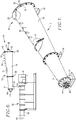
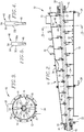
- the preconditioner 10 broadly includes an elongated, progressively tapered housing 12 having a substantially circular in cross-section housing wall 14, a large diameter end wall 16, and an opposed, smaller diameter end wall 18.
- the housing wall 14 has a material inlet 20 adjacent wall 16, and a downwardly opening outlet 22 proximal to wall 18.
- the housing walls thus define a frustoconical internal chamber 24.
- the housing 12 is supported by L-shaped mounts 26, 28.
- a first series of inlet ports 30 is provided along the top of housing wall 14, and a second series of ports 32 are located in a substantially tangential relationship to the housing wall 14 at the lower portion thereof.
- a clean-out door 34 is hingedly secured to the top of housing wall 14 and can be opened to facilitate access to chamber 24.
- the preconditioner 10 further includes an elongated shaft 36 extending the full length of chamber 24 substantially along the center line thereof.
- the outboard ends 38 and 40 of the shaft 36 are rotationally supported by bearing structures 42 and 44 respectively supported on the end walls 16 and 18.
- a drive assembly (not shown) is operably coupled to the end 38 of shaft 36 in order to rotate the latter at relatively high speeds (e.g., 400-900 rpm).
- Such a drive assembly would typically include a drive motor and gear reduction assembly.
- a variable speed drive may be used in this context, so as to allow infinite adjustment of the speed of rotation of the shaft, as well as controlling the direction of rotation thereof.
- a plurality of outwardly extending paddle-type mixing elements 46 are secured to shaft 36 along the length thereof.
- Each mixing element 46 includes a threaded shank 48, as well as a substantially flat paddle section 50 having opposed side margins 50a and 50b and a width greater than the width of the shank 48.
- each shank portion is threaded into an appropriate threaded bore 52 in shaft 36, with the paddle section 50 extending substantially radially relative to the longitudinal axis of the shaft 36.
- the elements 46 are both laterally spaced apart along the length of shaft 36, but are also circumferentially spaced about the periphery thereof.
- Each of the paddle sections 50 has an outermost margin 54, which is located in close adjacency (no more than about 1.27 cm (one-half inch)) to the inner surface of housing wall 14.
- the axially spaced apart outer margins 54 of the elements 46 cooperatively define a taper which, in preferred forms, is substantially identical with the taper of housing wall 14.
- the elements 46 have different overall lengths from a point proximal to end wall 16 to the remote end of the shaft 36 proximal to end wall 18. This size difference is illustrated in Figs. 4 and 5 , where it will be seen that both the shank 48 and the paddle section 50 of the comparative mixing elements are of different lengths.
- the orientation of the respective paddles may be altered.
- all of the elements 46 are oriented in a neutral position relative to the rotation direction of shaft 36 and the longitudinal axis of the shaft (i.e., the paddle sections 50 lie in planes perpendicular to the shaft axis).
- some or all of the mixing elements 46 may be oriented in a negative angular position. For example, if the shaft 36 is rotated in a clockwise direction (see Fig.
- the flow-retarding mixing elements would be oriented at an angle such that the margin 50a is closer to end wall 16 than the opposite margin 50b, and the planes of the paddle sections 50 would be at an angle relative to the shaft longitudinal axis.
- the degree of flow retardation would depend upon the number of negatively positioned mixing elements, as well as the angular orientation thereof; usually, this angle is from about 2-20° relative to the longitudinal axis of the shaft.
- some or all of the mixing elements 46 may be positioned in a positive flow-increasing position. Such positions would be opposite to the negative positions, and in the example given above, the flow-increasing elements 46 would be angularly oriented so that the margins 50b would be closer to the wall 16 than the corresponding margins 50a, and the paddle section planes would be at an angle relative to the shaft longitudinal axis.
- the preconditioner 10 is mounted upstream of a single screw extruder 56.
- appropriate support structure is provided to support the mounts 26, 28 and thus maintain preconditioner 10 in the illustrated elevated condition.
- the preconditioner 10 is oriented at a slight downward angle from end wall 16 to end wall 18, relative to the horizontal and to the longitudinal axis of extruder 56. This angle is preferably from about 1.5-10°, more preferably from about 2-5°.
- the extruder 56 is itself conventional and includes an elongated, multiple-section barrel 58 having an inlet 60 and a restricted orifice die outlet 62. Internally, the extruder 56 has an elongated, helically flighted, axially rotatable screw assembly (not shown) powered by drive unit 64. As depicted in Fig. 6 , the preconditioner outlet 22 is coupled with barrel inlet 60 by means of a tubular transition 66.
- human food or animal feed ingredients are delivered to inlet 20 of preconditioner 10, passed through chamber 24, and delivered from outlet 22.
- the shaft 36 is rotated and steam and/or water is injected through the ports 30 and 32.
- the high speed rotation of the shaft 36 causes intense mixing of the ingredients with the water and/or steam in order to moisturize and partially precook the ingredients.
- the degree of moisturization is at least about 18% by weight, and a cook value, as determined by the extent of gelatinization of starch in the ingredients, of from about 15-60%, more preferably from about 20-35%.
- the preconditioner 10 operates at substantially atmospheric pressure within chamber 24 and across outlet 22.
- the preconditioned ingredients delivered to extruder 56 are subjected to increasing levels of temperature, pressure, and shear within barrel 58, and are then extruded through die plate 62 as finished, fully-cooked food or feed products.
- a series of test runs was carried out using the preconditioner of Figs. 1-5 , wherein the shaft was equipped with 61 beaters ranging in length from 28.91 cm (11.38 inches) at the inlet end of the housing to 11.73 cm (4.62 inches) at the outlet end thereof.
- the housing wall had a progressive taper of 6.68°.
- the open area of the housing input was 176.97 cm 2 (27.43 sq. in.), whereas the area of the output was 292.90 cm 2 (45.4 sq. in.).
- a pet food recipe was processed, made up of 53% corn, 22% poultry meal, 15% soybean meal, and 10% corn gluten meal (all percentages by weight).
- the dry recipe was fed to the preconditioner inlet at a predetermined rate, while the shaft was rotated at a selected rpm. Water and steam were injected into the preconditioner housing, and retention times, moisturization, and cook values were measured for each test. the results of this series of runs are set forth below.
- the mixing element configuration was changed so that the first 47 of the elements, beginning at the large diameter end of the housing, were maintained in the negative 15° orientation, while the next 10 elements were oriented in a forward 15° position, and the remaining 4 elements were positioned at a negative 4° position.
- the preconditioner was able to deliver 2268 kg/hr (5000 lbs/hr) of preconditioned material at 400 rpm.
Landscapes
- Chemical & Material Sciences (AREA)
- Life Sciences & Earth Sciences (AREA)
- Polymers & Plastics (AREA)
- Engineering & Computer Science (AREA)
- Food Science & Technology (AREA)
- Chemical Kinetics & Catalysis (AREA)
- Zoology (AREA)
- Animal Husbandry (AREA)
- Manufacturing & Machinery (AREA)
- Birds (AREA)
- Mixers Of The Rotary Stirring Type (AREA)
- Apparatuses For Bulk Treatment Of Fruits And Vegetables And Apparatuses For Preparing Feeds (AREA)
- Fodder In General (AREA)
Claims (14)
- Dispositif de préconditionnement (10) apte à humidifier et cuire partiellement une matière alimentaire ou d'alimentation avant son traitement en aval, ledit dispositif de préconditionnement (10) comprenant :un boîtier de forme allongée (12) présentant une entrée (20) et une sortie opposée (22),un arbre axialement rotatif de forme allongée (36) s'étendant le long de la longueur dudit boîtier (12) et comportant une pluralité d'éléments de mélange espacés axialement les uns des autres et s'étendant vers l'extérieur (46) supportés par l'arbre (36) et présentant chacun une marge extérieure (54) distante de l'arbre (36),les marges extérieures espacées (54) desdits éléments de mélange (46) étant espacées dudit boîtier (12) d'une distance ne dépassant pas 1,27 cm (1/2 pouce) et ledit arbre (36) étant apte à tourner à une vitesse de 400 tr/min à 900 tr/min, etledit dispositif de préconditionnement (10) étant apte à précuire ladite matière et à atteindre une valeur de cuisson de 15 % à 60 %,caractérisé en ce que ledit boîtier (12) a une extrémité de grand diamètre (16) à proximité de ladite entrée (20), une extrémité de petit diamètre (18) à proximité de ladite sortie (22), et une section de paroi conique (14) entre lesdites extrémités de boîtier (16, 18), lesdites marges extérieures espacées (54) desdits éléments de mélange (46) définissant de façon coopérative un cône le long de la longueur de la section conique (14) dudit boîtier (12).
- Dispositif de préconditionnement (10) selon la revendication 1, dans lequel ladite paroi de boîtier (14) est progressivement rétrécie sur toute sa longueur suivant un angle de 2° à 9°.
- Dispositif de préconditionnement (10) selon la revendication 1, dans lequel ledit boîtier (12) a un rapport L/D allant de 3 à 8, L étant la longueur dudit boîtier (12) entre lesdites extrémités de boîtier (16, 18), et D étant le diamètre de l'extrémité de grand diamètre (16) du boîtier (12).
- Dispositif de préconditionnement (10) selon la revendication 1, dans lequel ledit dispositif de préconditionnement est apte à retenir ladite matière dans sa partie intérieure pendant une durée de 0,6 min à 4 min.
- Dispositif de préconditionnement (10) selon la revendication 1, dans lequel lesdits éléments de mélange (46) comprennent chacun une tige (48) fixée audit arbre (36) et supportant une section de palette s'étendant vers l'extérieur (50) ayant une largeur supérieure à la largeur de ladite tige (48).
- Dispositif de préconditionnement (10) selon la revendication 1, dans lequel des éléments sélectionnés parmi lesdits éléments de mélange (46) sont orientés dans une position neutre par rapport à la direction de rotation dudit arbre (36), et d'autres éléments de mélange (46) sont orientés dans une position angulaire négative par rapport à la direction de rotation dudit arbre (36), de telle manière que le temps de séjour des matières qui passent dans ledit dispositif de préconditionnement (10) est augmenté.
- Système d'extrusion comprenant :un dispositif de préconditionnement (10) selon l'une quelconque des revendications 1 à 6, etune extrudeuse (56) accouplée fonctionnellement audit dispositif de préconditionnement (10) et comprenant un canon de forme allongée (58) ayant une entrée (60) en communication fonctionnelle avec ladite sortie de boîtier (22), une sortie de filière à orifice restreint (62) distante de ladite entrée (20), et un ensemble de vis à filet hélicoïdal de forme allongée et rotative axialement à l'intérieur dudit canon (58) et apte à déplacer de la matière préconditionnée dudit dispositif de préconditionnement (10) vers et à travers ladite sortie de filière à orifice restreint (62).
- Système selon la revendication 7, dans lequel ledit boîtier (12) présente un axe longitudinal, ledit dispositif de préconditionnement (10) étant orienté avec ledit axe longitudinal qui est à un angle de 1,5° à 10° par rapport à l'horizontale, et dans lequel ladite entrée (20) est plus haute que ladite sortie (22).
- Procédé de traitement d'une matière alimentaire ou d'alimentation comprenant l'étape consistant à faire passer la matière dans le dispositif de préconditionnement (10) de la revendication 1, afin de cuire au moins partiellement et d'humidifier la matière.
- Procédé selon la revendication 9, comprenant l'étape consistant à retenir ladite matière dans ledit boîtier (12) pendant une durée de 0,6 min à 4 min.
- Procédé selon la revendication 9, comprenant l'étape consistant à humidifier ladite matière jusqu'à un niveau d'humidité d'au moins 18 % en poids, sur base humide.
- Procédé selon la revendication 11, dans lequel ledit niveau est de 20 % à 40 % en poids, sur base humide.
- Procédé selon la revendication 9, comprenant l'étape consistant à traiter ladite matière substantiellement à la pression atmosphérique à l'intérieur dudit boîtier (12) et à ladite sortie (22).
- Procédé selon la revendication 9, comprenant l'étape consistant à injecter de l'eau ou de la vapeur dans ledit boîtier (12) au cours dudit traitement de ladite matière.
Priority Applications (1)
| Application Number | Priority Date | Filing Date | Title |
|---|---|---|---|
| PL11822315T PL2544559T3 (pl) | 2010-08-30 | 2011-08-09 | Urządzenie do obróbki wstępnej do układów wytłaczania |
Applications Claiming Priority (3)
| Application Number | Priority Date | Filing Date | Title |
|---|---|---|---|
| US12/871,527 US7883263B1 (en) | 2010-08-30 | 2010-08-30 | Preconditioner for extrusion systems |
| US12/978,777 US8944672B2 (en) | 2010-08-30 | 2010-12-27 | Preconditioner for extrusion systems |
| PCT/US2011/047111 WO2012030487A2 (fr) | 2010-08-30 | 2011-08-09 | Dispositif de prétraitement amélioré pour systèmes d'extrusion |
Publications (3)
| Publication Number | Publication Date |
|---|---|
| EP2544559A2 EP2544559A2 (fr) | 2013-01-16 |
| EP2544559A4 EP2544559A4 (fr) | 2015-12-30 |
| EP2544559B1 true EP2544559B1 (fr) | 2017-12-13 |
Family
ID=43531906
Family Applications (1)
| Application Number | Title | Priority Date | Filing Date |
|---|---|---|---|
| EP11822315.5A Active EP2544559B1 (fr) | 2010-08-30 | 2011-08-09 | Dispositif de prétraitement pour systèmes d'extrusion |
Country Status (10)
| Country | Link |
|---|---|
| US (2) | US7883263B1 (fr) |
| EP (1) | EP2544559B1 (fr) |
| CN (2) | CN102917608B (fr) |
| BR (1) | BR112012020171B1 (fr) |
| DK (1) | DK2544559T3 (fr) |
| ES (1) | ES2659020T3 (fr) |
| NO (1) | NO2544559T3 (fr) |
| PL (1) | PL2544559T3 (fr) |
| TW (1) | TWI546015B (fr) |
| WO (1) | WO2012030487A2 (fr) |
Cited By (1)
| Publication number | Priority date | Publication date | Assignee | Title |
|---|---|---|---|---|
| USD1057770S1 (en) | 2023-05-12 | 2025-01-14 | Bühler AG | Food and feed industry machine (extruder) |
Families Citing this family (20)
| Publication number | Priority date | Publication date | Assignee | Title |
|---|---|---|---|---|
| US8641266B2 (en) * | 2008-06-27 | 2014-02-04 | William Ray McIntire | Horizontal-flow hydration apparatus |
| US20100062093A1 (en) * | 2008-09-11 | 2010-03-11 | Wenger Manufacturing, Inc. | Method and apparatus for producing fully cooked extrudates with significantly reduced specific mechanical energy inputs |
| US7883263B1 (en) * | 2010-08-30 | 2011-02-08 | Wenger Manufacturing, Inc. | Preconditioner for extrusion systems |
| RU2672291C2 (ru) * | 2012-01-25 | 2018-11-13 | Карджилл, Инкорпорейтед | Таблетки, содержащие крахмал и белок, способ их получения и применение |
| US9028133B2 (en) * | 2013-04-09 | 2015-05-12 | Wenger Manufacturing, Inc. | Tapered barrel twin shaft preconditioner |
| WO2014168763A1 (fr) * | 2013-04-09 | 2014-10-16 | Wenger Manufacturing, Inc. | Pré-conditionneur double arbre à fût conique |
| US9713893B2 (en) | 2013-07-09 | 2017-07-25 | Wenger Manufacturing, Inc. | Method of preconditioning comestible materials using steam/water static mixer |
| CN103604394B (zh) * | 2013-10-19 | 2017-01-04 | 沈阳黎明航空发动机(集团)有限责任公司 | 一种安装板带有空间角度的叶片锻件加工方法 |
| CN104689750A (zh) * | 2015-03-09 | 2015-06-10 | 苏州洛特兰新材料科技有限公司 | 新型陶瓷搅拌器 |
| WO2017033877A1 (fr) * | 2015-08-26 | 2017-03-02 | 株式会社サタケ | Dispositif de stérilisation à la vapeur surchauffée |
| US10434483B2 (en) | 2017-02-15 | 2019-10-08 | Wenger Manufacturing Inc. | High thermal transfer hollow core extrusion screw assembly |
| US20190075822A1 (en) | 2017-09-08 | 2019-03-14 | Wenger Manufacturing Inc. | Method and apparatus for production of high meat content pet foods |
| WO2019182630A1 (fr) | 2018-03-20 | 2019-09-26 | Wenger Manufacturing Inc. | Procédé et appareil de production d'aliments pour animaux de compagnie à teneur élevée en viande |
| CN109349145A (zh) * | 2018-09-28 | 2019-02-19 | 安徽省兵杰生态农业发展有限公司 | 一种养猪用混合下料一体化喂食装置 |
| US10736340B1 (en) | 2019-02-27 | 2020-08-11 | Wenger Manufacturing Inc. | Dual extrusion method and apparatus for pet food production using meat slurries |
| US12240142B2 (en) * | 2020-01-23 | 2025-03-04 | Siempelkamp Maschinen-Und Anlagenbau Gmbh | Method of glue-coating plant particles |
| US11344854B2 (en) | 2020-03-12 | 2022-05-31 | Knauf Gips Kg | Mixer rotor pin with hole |
| CN112808094A (zh) * | 2021-01-14 | 2021-05-18 | 海南省农业科学院畜牧兽医研究所 | 一种畜牧养殖用饲料混合设备 |
| EP4289284A4 (fr) * | 2021-03-01 | 2024-08-07 | Mizkan Holdings Co., Ltd. | Procédé de production d'une composition solide contenant de l'amidon pour une cuisson à la chaleur |
| CN115226912B (zh) * | 2022-07-22 | 2023-06-23 | 安徽宏亮饲料科技有限公司 | 一种提高牛羊消化率饲料的制备机及方法 |
Family Cites Families (75)
| Publication number | Priority date | Publication date | Assignee | Title |
|---|---|---|---|---|
| US617983A (en) * | 1899-01-17 | Robert dietrich | ||
| US431372A (en) * | 1890-07-01 | Mash-tub | ||
| US299766A (en) * | 1884-06-03 | farmer | ||
| US296792A (en) * | 1884-04-15 | Paint-mixer | ||
| US1411103A (en) * | 1921-03-21 | 1922-03-28 | Borden Co | Method of aerating liquescent material and apparatus in aid thereof |
| US1767102A (en) * | 1928-03-08 | 1930-06-24 | Thorne Carl Busch | Mixing machine |
| US2087492A (en) * | 1932-05-02 | 1937-07-20 | Delbert T Hulse | Grinding and mixing hammer mill |
| GB400769A (en) * | 1932-10-19 | 1933-11-02 | Albert Morgan Phillips | Improvements in feed mixers |
| US2029690A (en) * | 1933-07-10 | 1936-02-04 | Standard Oil Co | Process and apparatus for contacting two liquids |
| US2029691A (en) * | 1933-08-12 | 1936-02-04 | Standard Oil Co | Countercurrent contactor |
| US2278051A (en) * | 1940-04-11 | 1942-03-31 | American Viscose Corp | Apparatus for cutting and mixing |
| US2400202A (en) * | 1942-05-15 | 1946-05-14 | Kelderhouse Austin Henry | Feed mixer |
| GB929023A (en) | 1959-01-28 | 1963-06-19 | Machf Frans Smulders Nv | Improvements in and relating to apparatus for the mixing of two or more substances |
| US3090606A (en) * | 1959-09-11 | 1963-05-21 | Strong Scott Mfg Company | Rotary mixing device |
| US3229002A (en) * | 1964-06-09 | 1966-01-11 | Wedco | Method of treating thermoplastic resin in finely divided form to improve flowability |
| US3249342A (en) * | 1964-07-14 | 1966-05-03 | Laurits A Mikkelsen | Mixer |
| US3334873A (en) * | 1964-08-14 | 1967-08-08 | Stickelber & Sons Inc | Continuous mixer |
| US3332368A (en) * | 1965-12-21 | 1967-07-25 | Marion Corp | Continuous dough mixer |
| CH460718A (de) * | 1967-06-22 | 1968-08-15 | Buss Ag | Zusatzeinrichtung an einer Misch- und Kneteinrichtung zur Weiterbehandlung von weichpastösen Produkten |
| FR2036249A5 (fr) * | 1969-03-07 | 1970-12-24 | Neyrpic Bmb | |
| US3719506A (en) * | 1971-06-18 | 1973-03-06 | Gen Foods Corp | Coffee extract slush extrusion apparatus |
| DE2334189C2 (de) * | 1973-07-05 | 1984-12-06 | Sapco Systemanalyse und Projektcontrol GmbH, 4000 Düsseldorf | Verfahren und Vorrichtung zur Herstellung eines Kunststoff-Füllstoff-Gemisches |
| US4055673A (en) * | 1974-02-08 | 1977-10-25 | Gebrueder Buehler Ag | Method of moistening whole grains |
| US3901482A (en) * | 1974-05-20 | 1975-08-26 | Marion Corp | Dough mixer |
| DE2626757C2 (de) | 1975-07-09 | 1984-03-15 | Meyer AG Zuchwil, Zuchwil | Rührwerkmühle, insbesondere Kolloidmühle |
| US4173419A (en) * | 1976-07-07 | 1979-11-06 | Arie Blok | Rotary mixer |
| US4346652A (en) | 1977-04-26 | 1982-08-31 | Ruyter Peter W A De | Apparatus for making a meat analog |
| US4171165A (en) * | 1978-07-17 | 1979-10-16 | Diamond Insulation Industries, Inc. | Cellulose insulation storage bin with improved debridger |
| GB2048755B (en) * | 1979-02-10 | 1982-12-08 | American Pelletizing Corp | Mixing and pelletizing machine |
| US4322169A (en) | 1980-06-12 | 1982-03-30 | Wood Randolph C | Clay mixing apparatus |
| US4390285A (en) * | 1980-08-24 | 1983-06-28 | Draiswerke Gmbh | Method and apparatus for mixing solids with liquids, in particular for gluing wood chips |
| US4478519A (en) | 1981-06-10 | 1984-10-23 | Raul Guibert | Automatic paste-producing apparatus |
| US4650343A (en) * | 1984-11-06 | 1987-03-17 | Doom Lewis W G | Method of mixing or drying particulate material |
| US4723849A (en) * | 1985-08-21 | 1988-02-09 | Conair, Inc. | Compounding blender for plastic materials |
| US4752139A (en) * | 1986-10-14 | 1988-06-21 | Wenger Manufacturing, Inc. | Preconditioning apparatus for extruder |
| CN2030809U (zh) * | 1988-04-22 | 1989-01-18 | 惠来县二轻隆江农机厂 | 饲料搅拌机 |
| CN1030684C (zh) * | 1988-06-25 | 1996-01-17 | 温吉尔制造公司 | 连续生产速煮食品的方法 |
| US4989504A (en) * | 1988-11-09 | 1991-02-05 | Sherping Systems, Inc. | Food processing vat |
| US5161888A (en) * | 1991-09-26 | 1992-11-10 | Wenger Manufacturing, Inc. | Dual shaft preconditioning device having differentiated conditioning zones for farinaceous materials |
| DE4225168C2 (de) * | 1992-07-30 | 1994-05-19 | Mti Mischtechnik Industrieanla | Durchlaufmischer |
| US5460448A (en) * | 1994-04-08 | 1995-10-24 | Woolsey; Rick L. | Preconditioning apparatus having intermeshing beaters with a variable pitch helix |
| US5496108A (en) | 1994-07-27 | 1996-03-05 | Sukup Manufacturing Company | Method and means for adding moisture to particulate material |
| US5783240A (en) * | 1996-10-16 | 1998-07-21 | Wenger Manufacturing, Inc. | Method of producing high protein, high fat sinking aquatic feed |
| DE19710067C1 (de) | 1997-03-12 | 1998-12-03 | Maxit Holding Gmbh | Vorrichtung zum kontinuierlichen Anmachen von Schüttgut- oder Baustoffmischungen |
| US5932264A (en) | 1997-10-07 | 1999-08-03 | General Mills, Inc. | Method for preparing cooked cereal dough using twin screw preconditioning extruder |
| SE9802350D0 (sv) * | 1998-07-01 | 1998-07-01 | Borealis As | Mixing device |
| US6247394B1 (en) * | 1998-08-17 | 2001-06-19 | Wenger Manufacturing, Inc. | Method and apparatus for producing a pre-gelled starch product and normally sticky extrudates with minimal or no surfactant |
| US6349570B1 (en) * | 1999-04-14 | 2002-02-26 | Merkle Engineers, Inc. | In-barrel wetting screw charger |
| US6414054B1 (en) * | 1999-12-21 | 2002-07-02 | General Electric Company | Continuous preparation of heat-vulcanizable silicone compositions |
| US6340487B1 (en) * | 2000-03-28 | 2002-01-22 | Wenger Manufacturing, Inc. | Multiple purpose quick-changeover extrusion system |
| AU2001249571A1 (en) * | 2000-03-28 | 2001-10-08 | Wenger Manufacturing, Inc. | Multiple purpose quick-changeover extrusion system |
| US6648501B2 (en) * | 2000-12-19 | 2003-11-18 | Wenger Manufacturing, Inc. | System for homogeneously mixing plural incoming product streams of different composition |
| US6609819B2 (en) | 2001-07-24 | 2003-08-26 | Wenger Mfg | Twin screw extruder with conical non-parallel converging screws |
| US6719448B2 (en) | 2002-06-13 | 2004-04-13 | Wenger Manufacturing, Inc. | Method and apparatus for the simultaneous production of differently characterized extrudates |
| US7320583B2 (en) | 2003-04-16 | 2008-01-22 | Frito-Lay North America, Inc | Apparatus and method for producing colored extruded food products |
| US7331702B2 (en) | 2003-10-31 | 2008-02-19 | Reika Kogyo Kabushiki Kaisha | Agitation mixer |
| CN100503024C (zh) * | 2004-10-14 | 2009-06-24 | 黄建 | 一种新型饲料工业搅拌器 |
| US7448795B2 (en) * | 2006-10-23 | 2008-11-11 | Wenger Manufacturing, Inc. | Preconditioner having mixer shafts independently driven with variable frequency drives |
| US7674492B2 (en) * | 2006-10-23 | 2010-03-09 | Wenger Manufacturing, Inc. | Preconditioner having independently driven high-speed mixer shafts |
| JP5085929B2 (ja) * | 2006-12-27 | 2012-11-28 | 株式会社ツカサ | 粉粒体混合装置 |
| US8153178B2 (en) * | 2007-04-26 | 2012-04-10 | Carmel Engineering | Method for dispersion of a second phase into a non-Newtonian fluid base product |
| US8246240B2 (en) * | 2008-01-03 | 2012-08-21 | Wenger Manufacturing, Inc. | Single screw extruder for processing of low viscosity preconditioned materials |
| US7635217B2 (en) * | 2008-01-03 | 2009-12-22 | Wenger Manufacturing, Inc. | Extruder having variable mid-barrel restriction and adjacent high intensity mixing assembly |
| US20090297664A1 (en) | 2008-05-30 | 2009-12-03 | Jorrocks Pty Ltd | Low temperature forming of feeds |
| US20100062093A1 (en) | 2008-09-11 | 2010-03-11 | Wenger Manufacturing, Inc. | Method and apparatus for producing fully cooked extrudates with significantly reduced specific mechanical energy inputs |
| US7588789B1 (en) * | 2009-04-08 | 2009-09-15 | Wenger Manufacturing, Inc. | High capacity extrusion die assembly |
| DE102009057916B4 (de) * | 2009-05-15 | 2015-04-02 | Siempelkamp Maschinen- Und Anlagenbau Gmbh | Verfahren und Vorrichtung zum kontinuierlichen Mischen von Fasern mit einem Bindemittel |
| CN102482133B (zh) * | 2009-08-21 | 2014-12-10 | 尤米科尔股份公司及两合公司 | 混合装置 |
| US7794134B1 (en) * | 2010-02-24 | 2010-09-14 | Wenger Manufacturing, Inc. | Method of preconditioner control with reduced or zero waste |
| US20110262609A1 (en) * | 2010-04-26 | 2011-10-27 | Wenger Manufacturing, Inc. | Extrusion processing of high meat quantity feeds using preconditioner with hot air input |
| US7811617B1 (en) * | 2010-04-26 | 2010-10-12 | Wenger Manufacturing, Inc. | Extrusion processing of high meat quantity feeds using preconditioner with hot air input |
| US7883263B1 (en) * | 2010-08-30 | 2011-02-08 | Wenger Manufacturing, Inc. | Preconditioner for extrusion systems |
| KR101088095B1 (ko) * | 2011-04-18 | 2011-11-29 | 주식회사 에코그린텍 | 유기물의 분해 장치 및 그를 이용한 유기물의 분해 방법 |
| US8322272B1 (en) * | 2011-10-18 | 2012-12-04 | Wenger Manufacturing, Inc. | Method for positive feeding of preconditioned material into a twin screw extruder |
| US9713893B2 (en) * | 2013-07-09 | 2017-07-25 | Wenger Manufacturing, Inc. | Method of preconditioning comestible materials using steam/water static mixer |
-
2010
- 2010-08-30 US US12/871,527 patent/US7883263B1/en active Active
- 2010-12-27 US US12/978,777 patent/US8944672B2/en active Active
-
2011
- 2011-08-09 CN CN201180021519.2A patent/CN102917608B/zh not_active Expired - Fee Related
- 2011-08-09 EP EP11822315.5A patent/EP2544559B1/fr active Active
- 2011-08-09 CN CN201510855175.5A patent/CN105559118B/zh active Active
- 2011-08-09 WO PCT/US2011/047111 patent/WO2012030487A2/fr not_active Ceased
- 2011-08-09 ES ES11822315.5T patent/ES2659020T3/es active Active
- 2011-08-09 NO NO11822315A patent/NO2544559T3/no unknown
- 2011-08-09 PL PL11822315T patent/PL2544559T3/pl unknown
- 2011-08-09 BR BR112012020171-9A patent/BR112012020171B1/pt active IP Right Grant
- 2011-08-09 DK DK11822315.5T patent/DK2544559T3/en active
- 2011-08-10 TW TW100128511A patent/TWI546015B/zh active
Non-Patent Citations (1)
| Title |
|---|
| None * |
Cited By (2)
| Publication number | Priority date | Publication date | Assignee | Title |
|---|---|---|---|---|
| USD1057770S1 (en) | 2023-05-12 | 2025-01-14 | Bühler AG | Food and feed industry machine (extruder) |
| USD1125302S1 (en) | 2023-05-12 | 2026-05-05 | Bühler AG | Food and feed industry machine (extruder) |
Also Published As
| Publication number | Publication date |
|---|---|
| DK2544559T3 (en) | 2018-02-26 |
| BR112012020171B1 (pt) | 2022-03-29 |
| CN105559118A (zh) | 2016-05-11 |
| US20120052174A1 (en) | 2012-03-01 |
| EP2544559A2 (fr) | 2013-01-16 |
| EP2544559A4 (fr) | 2015-12-30 |
| NO2544559T3 (fr) | 2018-05-12 |
| US7883263B1 (en) | 2011-02-08 |
| ES2659020T3 (es) | 2018-03-13 |
| TWI546015B (zh) | 2016-08-21 |
| WO2012030487A2 (fr) | 2012-03-08 |
| CN102917608B (zh) | 2016-06-29 |
| BR112012020171A2 (pt) | 2021-04-13 |
| US8944672B2 (en) | 2015-02-03 |
| PL2544559T3 (pl) | 2018-05-30 |
| CN105559118B (zh) | 2017-10-03 |
| TW201210473A (en) | 2012-03-16 |
| WO2012030487A3 (fr) | 2012-05-31 |
| CN102917608A (zh) | 2013-02-06 |
| WO2012030487A8 (fr) | 2012-09-13 |
Similar Documents
| Publication | Publication Date | Title |
|---|---|---|
| US7883263B1 (en) | Preconditioner for extrusion systems | |
| US8827539B2 (en) | Twin screw extruders operating with significantly reduced specific mechanical energy inputs | |
| US8246240B2 (en) | Single screw extruder for processing of low viscosity preconditioned materials | |
| US8322272B1 (en) | Method for positive feeding of preconditioned material into a twin screw extruder | |
| EP2591848B1 (fr) | Préconditionneur amélioré doté d'arbres de malaxage à grande vitesse entraînés indépendamment | |
| US6688217B2 (en) | Twin screw extruder with conical non-parallel converging screws | |
| US20080094939A1 (en) | Preconditioner having independently driven high-speed mixer shafts | |
| US20090175120A1 (en) | Extruder having variable mid-barrel restriction and adjacent high intensity mixing assembly | |
| US9028133B2 (en) | Tapered barrel twin shaft preconditioner | |
| US20260007161A1 (en) | Extruder to nixtamalize maize fractions | |
| EP1778454A1 (fr) | Appareil d"extrusion et procede d"extrusion d"aliments a forte teneur en proteines | |
| WO2014168763A1 (fr) | Pré-conditionneur double arbre à fût conique | |
| Riaz | Role of extruders in food and feed industries. |
Legal Events
| Date | Code | Title | Description |
|---|---|---|---|
| PUAI | Public reference made under article 153(3) epc to a published international application that has entered the european phase |
Free format text: ORIGINAL CODE: 0009012 |
|
| 17P | Request for examination filed |
Effective date: 20120824 |
|
| AK | Designated contracting states |
Kind code of ref document: A2 Designated state(s): AL AT BE BG CH CY CZ DE DK EE ES FI FR GB GR HR HU IE IS IT LI LT LU LV MC MK MT NL NO PL PT RO RS SE SI SK SM TR |
|
| DAX | Request for extension of the european patent (deleted) | ||
| A4 | Supplementary search report drawn up and despatched |
Effective date: 20151201 |
|
| RIC1 | Information provided on ipc code assigned before grant |
Ipc: B01F 7/04 20060101ALI20151125BHEP Ipc: A23P 1/12 20060101AFI20151125BHEP Ipc: A23N 17/00 20060101ALI20151125BHEP |
|
| REG | Reference to a national code |
Ref country code: DE Ref legal event code: R079 Ref document number: 602011044227 Country of ref document: DE Free format text: PREVIOUS MAIN CLASS: A23P0001120000 Ipc: B01F0007040000 |
|
| GRAP | Despatch of communication of intention to grant a patent |
Free format text: ORIGINAL CODE: EPIDOSNIGR1 |
|
| RIC1 | Information provided on ipc code assigned before grant |
Ipc: B01F 7/04 20060101AFI20170530BHEP Ipc: A23P 30/20 20160101ALI20170530BHEP Ipc: A23K 40/10 20160101ALI20170530BHEP Ipc: A23K 40/25 20160101ALI20170530BHEP Ipc: A23N 17/00 20060101ALI20170530BHEP |
|
| INTG | Intention to grant announced |
Effective date: 20170622 |
|
| GRAS | Grant fee paid |
Free format text: ORIGINAL CODE: EPIDOSNIGR3 |
|
| GRAA | (expected) grant |
Free format text: ORIGINAL CODE: 0009210 |
|
| AK | Designated contracting states |
Kind code of ref document: B1 Designated state(s): AL AT BE BG CH CY CZ DE DK EE ES FI FR GB GR HR HU IE IS IT LI LT LU LV MC MK MT NL NO PL PT RO RS SE SI SK SM TR |
|
| REG | Reference to a national code |
Ref country code: GB Ref legal event code: FG4D |
|
| REG | Reference to a national code |
Ref country code: AT Ref legal event code: REF Ref document number: 953848 Country of ref document: AT Kind code of ref document: T Effective date: 20171215 Ref country code: CH Ref legal event code: EP |
|
| REG | Reference to a national code |
Ref country code: IE Ref legal event code: FG4D |
|
| REG | Reference to a national code |
Ref country code: DE Ref legal event code: R096 Ref document number: 602011044227 Country of ref document: DE |
|
| RAP2 | Party data changed (patent owner data changed or rights of a patent transferred) |
Owner name: WENGER MANUFACTURING INC. |
|
| REG | Reference to a national code |
Ref country code: DK Ref legal event code: T3 Effective date: 20180221 |
|
| REG | Reference to a national code |
Ref country code: ES Ref legal event code: FG2A Ref document number: 2659020 Country of ref document: ES Kind code of ref document: T3 Effective date: 20180313 Ref country code: SE Ref legal event code: TRGR |
|
| REG | Reference to a national code |
Ref country code: NL Ref legal event code: FP |
|
| REG | Reference to a national code |
Ref country code: LT Ref legal event code: MG4D |
|
| PG25 | Lapsed in a contracting state [announced via postgrant information from national office to epo] |
Ref country code: FI Free format text: LAPSE BECAUSE OF FAILURE TO SUBMIT A TRANSLATION OF THE DESCRIPTION OR TO PAY THE FEE WITHIN THE PRESCRIBED TIME-LIMIT Effective date: 20171213 Ref country code: LT Free format text: LAPSE BECAUSE OF FAILURE TO SUBMIT A TRANSLATION OF THE DESCRIPTION OR TO PAY THE FEE WITHIN THE PRESCRIBED TIME-LIMIT Effective date: 20171213 |
|
| REG | Reference to a national code |
Ref country code: NO Ref legal event code: T2 Effective date: 20171213 |
|
| REG | Reference to a national code |
Ref country code: AT Ref legal event code: MK05 Ref document number: 953848 Country of ref document: AT Kind code of ref document: T Effective date: 20171213 |
|
| PG25 | Lapsed in a contracting state [announced via postgrant information from national office to epo] |
Ref country code: RS Free format text: LAPSE BECAUSE OF FAILURE TO SUBMIT A TRANSLATION OF THE DESCRIPTION OR TO PAY THE FEE WITHIN THE PRESCRIBED TIME-LIMIT Effective date: 20171213 Ref country code: LV Free format text: LAPSE BECAUSE OF FAILURE TO SUBMIT A TRANSLATION OF THE DESCRIPTION OR TO PAY THE FEE WITHIN THE PRESCRIBED TIME-LIMIT Effective date: 20171213 Ref country code: HR Free format text: LAPSE BECAUSE OF FAILURE TO SUBMIT A TRANSLATION OF THE DESCRIPTION OR TO PAY THE FEE WITHIN THE PRESCRIBED TIME-LIMIT Effective date: 20171213 Ref country code: GR Free format text: LAPSE BECAUSE OF FAILURE TO SUBMIT A TRANSLATION OF THE DESCRIPTION OR TO PAY THE FEE WITHIN THE PRESCRIBED TIME-LIMIT Effective date: 20180314 Ref country code: BG Free format text: LAPSE BECAUSE OF FAILURE TO SUBMIT A TRANSLATION OF THE DESCRIPTION OR TO PAY THE FEE WITHIN THE PRESCRIBED TIME-LIMIT Effective date: 20180313 |
|
| PG25 | Lapsed in a contracting state [announced via postgrant information from national office to epo] |
Ref country code: EE Free format text: LAPSE BECAUSE OF FAILURE TO SUBMIT A TRANSLATION OF THE DESCRIPTION OR TO PAY THE FEE WITHIN THE PRESCRIBED TIME-LIMIT Effective date: 20171213 Ref country code: CY Free format text: LAPSE BECAUSE OF FAILURE TO SUBMIT A TRANSLATION OF THE DESCRIPTION OR TO PAY THE FEE WITHIN THE PRESCRIBED TIME-LIMIT Effective date: 20171213 Ref country code: SK Free format text: LAPSE BECAUSE OF FAILURE TO SUBMIT A TRANSLATION OF THE DESCRIPTION OR TO PAY THE FEE WITHIN THE PRESCRIBED TIME-LIMIT Effective date: 20171213 |
|
| REG | Reference to a national code |
Ref country code: FR Ref legal event code: PLFP Year of fee payment: 8 |
|
| PG25 | Lapsed in a contracting state [announced via postgrant information from national office to epo] |
Ref country code: AT Free format text: LAPSE BECAUSE OF FAILURE TO SUBMIT A TRANSLATION OF THE DESCRIPTION OR TO PAY THE FEE WITHIN THE PRESCRIBED TIME-LIMIT Effective date: 20171213 Ref country code: SM Free format text: LAPSE BECAUSE OF FAILURE TO SUBMIT A TRANSLATION OF THE DESCRIPTION OR TO PAY THE FEE WITHIN THE PRESCRIBED TIME-LIMIT Effective date: 20171213 Ref country code: RO Free format text: LAPSE BECAUSE OF FAILURE TO SUBMIT A TRANSLATION OF THE DESCRIPTION OR TO PAY THE FEE WITHIN THE PRESCRIBED TIME-LIMIT Effective date: 20171213 Ref country code: IS Free format text: LAPSE BECAUSE OF FAILURE TO SUBMIT A TRANSLATION OF THE DESCRIPTION OR TO PAY THE FEE WITHIN THE PRESCRIBED TIME-LIMIT Effective date: 20180413 |
|
| REG | Reference to a national code |
Ref country code: DE Ref legal event code: R097 Ref document number: 602011044227 Country of ref document: DE |
|
| PLBE | No opposition filed within time limit |
Free format text: ORIGINAL CODE: 0009261 |
|
| STAA | Information on the status of an ep patent application or granted ep patent |
Free format text: STATUS: NO OPPOSITION FILED WITHIN TIME LIMIT |
|
| 26N | No opposition filed |
Effective date: 20180914 |
|
| PG25 | Lapsed in a contracting state [announced via postgrant information from national office to epo] |
Ref country code: SI Free format text: LAPSE BECAUSE OF FAILURE TO SUBMIT A TRANSLATION OF THE DESCRIPTION OR TO PAY THE FEE WITHIN THE PRESCRIBED TIME-LIMIT Effective date: 20171213 |
|
| PG25 | Lapsed in a contracting state [announced via postgrant information from national office to epo] |
Ref country code: MC Free format text: LAPSE BECAUSE OF FAILURE TO SUBMIT A TRANSLATION OF THE DESCRIPTION OR TO PAY THE FEE WITHIN THE PRESCRIBED TIME-LIMIT Effective date: 20171213 |
|
| REG | Reference to a national code |
Ref country code: CH Ref legal event code: PL |
|
| PG25 | Lapsed in a contracting state [announced via postgrant information from national office to epo] |
Ref country code: LU Free format text: LAPSE BECAUSE OF NON-PAYMENT OF DUE FEES Effective date: 20180809 Ref country code: CH Free format text: LAPSE BECAUSE OF NON-PAYMENT OF DUE FEES Effective date: 20180831 Ref country code: LI Free format text: LAPSE BECAUSE OF NON-PAYMENT OF DUE FEES Effective date: 20180831 |
|
| PG25 | Lapsed in a contracting state [announced via postgrant information from national office to epo] |
Ref country code: MT Free format text: LAPSE BECAUSE OF NON-PAYMENT OF DUE FEES Effective date: 20180809 |
|
| PG25 | Lapsed in a contracting state [announced via postgrant information from national office to epo] |
Ref country code: HU Free format text: LAPSE BECAUSE OF FAILURE TO SUBMIT A TRANSLATION OF THE DESCRIPTION OR TO PAY THE FEE WITHIN THE PRESCRIBED TIME-LIMIT; INVALID AB INITIO Effective date: 20110809 Ref country code: PT Free format text: LAPSE BECAUSE OF FAILURE TO SUBMIT A TRANSLATION OF THE DESCRIPTION OR TO PAY THE FEE WITHIN THE PRESCRIBED TIME-LIMIT Effective date: 20171213 |
|
| PG25 | Lapsed in a contracting state [announced via postgrant information from national office to epo] |
Ref country code: MK Free format text: LAPSE BECAUSE OF NON-PAYMENT OF DUE FEES Effective date: 20171213 |
|
| PG25 | Lapsed in a contracting state [announced via postgrant information from national office to epo] |
Ref country code: AL Free format text: LAPSE BECAUSE OF FAILURE TO SUBMIT A TRANSLATION OF THE DESCRIPTION OR TO PAY THE FEE WITHIN THE PRESCRIBED TIME-LIMIT Effective date: 20171213 |
|
| PGFP | Annual fee paid to national office [announced via postgrant information from national office to epo] |
Ref country code: NL Payment date: 20200826 Year of fee payment: 10 |
|
| PGFP | Annual fee paid to national office [announced via postgrant information from national office to epo] |
Ref country code: DK Payment date: 20200827 Year of fee payment: 10 Ref country code: IE Payment date: 20200827 Year of fee payment: 10 Ref country code: NO Payment date: 20200827 Year of fee payment: 10 Ref country code: CZ Payment date: 20200729 Year of fee payment: 10 Ref country code: DE Payment date: 20200827 Year of fee payment: 10 Ref country code: ES Payment date: 20200901 Year of fee payment: 10 Ref country code: GB Payment date: 20200827 Year of fee payment: 10 Ref country code: FR Payment date: 20200825 Year of fee payment: 10 |
|
| PGFP | Annual fee paid to national office [announced via postgrant information from national office to epo] |
Ref country code: PL Payment date: 20200721 Year of fee payment: 10 Ref country code: SE Payment date: 20200827 Year of fee payment: 10 Ref country code: IT Payment date: 20200821 Year of fee payment: 10 Ref country code: BE Payment date: 20200827 Year of fee payment: 10 |
|
| REG | Reference to a national code |
Ref country code: DE Ref legal event code: R079 Ref document number: 602011044227 Country of ref document: DE Free format text: PREVIOUS MAIN CLASS: B01F0007040000 Ipc: B01F0027700000 |
|
| REG | Reference to a national code |
Ref country code: DE Ref legal event code: R119 Ref document number: 602011044227 Country of ref document: DE |
|
| REG | Reference to a national code |
Ref country code: DK Ref legal event code: EBP Effective date: 20210831 |
|
| REG | Reference to a national code |
Ref country code: NO Ref legal event code: MMEP |
|
| REG | Reference to a national code |
Ref country code: SE Ref legal event code: EUG |
|
| REG | Reference to a national code |
Ref country code: NL Ref legal event code: MM Effective date: 20210901 |
|
| REG | Reference to a national code |
Ref country code: BE Ref legal event code: MM Effective date: 20210831 |
|
| GBPC | Gb: european patent ceased through non-payment of renewal fee |
Effective date: 20210809 |
|
| PG25 | Lapsed in a contracting state [announced via postgrant information from national office to epo] |
Ref country code: SE Free format text: LAPSE BECAUSE OF NON-PAYMENT OF DUE FEES Effective date: 20210810 Ref country code: NO Free format text: LAPSE BECAUSE OF NON-PAYMENT OF DUE FEES Effective date: 20210831 Ref country code: CZ Free format text: LAPSE BECAUSE OF NON-PAYMENT OF DUE FEES Effective date: 20210809 |
|
| PG25 | Lapsed in a contracting state [announced via postgrant information from national office to epo] |
Ref country code: NL Free format text: LAPSE BECAUSE OF NON-PAYMENT OF DUE FEES Effective date: 20210901 |
|
| PG25 | Lapsed in a contracting state [announced via postgrant information from national office to epo] |
Ref country code: IT Free format text: LAPSE BECAUSE OF NON-PAYMENT OF DUE FEES Effective date: 20210809 Ref country code: IE Free format text: LAPSE BECAUSE OF NON-PAYMENT OF DUE FEES Effective date: 20210809 Ref country code: GB Free format text: LAPSE BECAUSE OF NON-PAYMENT OF DUE FEES Effective date: 20210809 Ref country code: FR Free format text: LAPSE BECAUSE OF NON-PAYMENT OF DUE FEES Effective date: 20210831 Ref country code: DK Free format text: LAPSE BECAUSE OF NON-PAYMENT OF DUE FEES Effective date: 20210831 Ref country code: DE Free format text: LAPSE BECAUSE OF NON-PAYMENT OF DUE FEES Effective date: 20220301 Ref country code: BE Free format text: LAPSE BECAUSE OF NON-PAYMENT OF DUE FEES Effective date: 20210831 |
|
| REG | Reference to a national code |
Ref country code: ES Ref legal event code: FD2A Effective date: 20221027 |
|
| PG25 | Lapsed in a contracting state [announced via postgrant information from national office to epo] |
Ref country code: ES Free format text: LAPSE BECAUSE OF NON-PAYMENT OF DUE FEES Effective date: 20210810 |
|
| P01 | Opt-out of the competence of the unified patent court (upc) registered |
Effective date: 20230529 |
|
| PG25 | Lapsed in a contracting state [announced via postgrant information from national office to epo] |
Ref country code: PL Free format text: LAPSE BECAUSE OF NON-PAYMENT OF DUE FEES Effective date: 20210809 |
|
| PG25 | Lapsed in a contracting state [announced via postgrant information from national office to epo] |
Ref country code: PL Free format text: LAPSE BECAUSE OF NON-PAYMENT OF DUE FEES Effective date: 20210809 |
|
| PGFP | Annual fee paid to national office [announced via postgrant information from national office to epo] |
Ref country code: TR Payment date: 20250725 Year of fee payment: 15 |