EP2544632B1 - Schultergelenkersatz - Google Patents
Schultergelenkersatz Download PDFInfo
- Publication number
- EP2544632B1 EP2544632B1 EP11753831.4A EP11753831A EP2544632B1 EP 2544632 B1 EP2544632 B1 EP 2544632B1 EP 11753831 A EP11753831 A EP 11753831A EP 2544632 B1 EP2544632 B1 EP 2544632B1
- Authority
- EP
- European Patent Office
- Prior art keywords
- glenoid
- implant
- bone
- articulating surface
- humeral
- Prior art date
- Legal status (The legal status is an assumption and is not a legal conclusion. Google has not performed a legal analysis and makes no representation as to the accuracy of the status listed.)
- Active
Links
Images















Classifications
-
- A—HUMAN NECESSITIES
- A61—MEDICAL OR VETERINARY SCIENCE; HYGIENE
- A61F—FILTERS IMPLANTABLE INTO BLOOD VESSELS; PROSTHESES; DEVICES PROVIDING PATENCY TO, OR PREVENTING COLLAPSING OF, TUBULAR STRUCTURES OF THE BODY, e.g. STENTS; ORTHOPAEDIC, NURSING OR CONTRACEPTIVE DEVICES; FOMENTATION; TREATMENT OR PROTECTION OF EYES OR EARS; BANDAGES, DRESSINGS OR ABSORBENT PADS; FIRST-AID KITS
- A61F2/00—Filters implantable into blood vessels; Prostheses, i.e. artificial substitutes or replacements for parts of the body; Appliances for connecting them with the body; Devices providing patency to, or preventing collapsing of, tubular structures of the body, e.g. stents
- A61F2/02—Prostheses implantable into the body
- A61F2/30—Joints
- A61F2/40—Joints for shoulders
- A61F2/4081—Glenoid components, e.g. cups
-
- A—HUMAN NECESSITIES
- A61—MEDICAL OR VETERINARY SCIENCE; HYGIENE
- A61B—DIAGNOSIS; SURGERY; IDENTIFICATION
- A61B17/00—Surgical instruments, devices or methods
- A61B17/14—Surgical saws
- A61B17/15—Guides therefor
-
- A—HUMAN NECESSITIES
- A61—MEDICAL OR VETERINARY SCIENCE; HYGIENE
- A61B—DIAGNOSIS; SURGERY; IDENTIFICATION
- A61B17/00—Surgical instruments, devices or methods
- A61B17/16—Instruments for performing osteoclasis; Drills or chisels for bones; Trepans
- A61B17/1659—Surgical rasps, files, planes, or scrapers
-
- A—HUMAN NECESSITIES
- A61—MEDICAL OR VETERINARY SCIENCE; HYGIENE
- A61B—DIAGNOSIS; SURGERY; IDENTIFICATION
- A61B17/00—Surgical instruments, devices or methods
- A61B17/16—Instruments for performing osteoclasis; Drills or chisels for bones; Trepans
- A61B17/1662—Instruments for performing osteoclasis; Drills or chisels for bones; Trepans for particular parts of the body
- A61B17/1684—Instruments for performing osteoclasis; Drills or chisels for bones; Trepans for particular parts of the body for the shoulder
-
- A—HUMAN NECESSITIES
- A61—MEDICAL OR VETERINARY SCIENCE; HYGIENE
- A61B—DIAGNOSIS; SURGERY; IDENTIFICATION
- A61B17/00—Surgical instruments, devices or methods
- A61B17/56—Surgical instruments or methods for treatment of bones or joints; Devices specially adapted therefor
- A61B17/58—Surgical instruments or methods for treatment of bones or joints; Devices specially adapted therefor for osteosynthesis, e.g. bone plates, screws or setting implements
- A61B17/68—Internal fixation devices, including fasteners and spinal fixators, even if a part thereof projects from the skin
- A61B17/84—Fasteners therefor or fasteners being internal fixation devices
- A61B17/86—Pins or screws or threaded wires; nuts therefor
-
- A—HUMAN NECESSITIES
- A61—MEDICAL OR VETERINARY SCIENCE; HYGIENE
- A61B—DIAGNOSIS; SURGERY; IDENTIFICATION
- A61B17/00—Surgical instruments, devices or methods
- A61B17/56—Surgical instruments or methods for treatment of bones or joints; Devices specially adapted therefor
- A61B17/58—Surgical instruments or methods for treatment of bones or joints; Devices specially adapted therefor for osteosynthesis, e.g. bone plates, screws or setting implements
- A61B17/88—Osteosynthesis instruments; Methods or means for implanting or extracting internal or external fixation devices
- A61B17/8802—Equipment for handling bone cement or other fluid fillers
-
- A—HUMAN NECESSITIES
- A61—MEDICAL OR VETERINARY SCIENCE; HYGIENE
- A61B—DIAGNOSIS; SURGERY; IDENTIFICATION
- A61B17/00—Surgical instruments, devices or methods
- A61B17/56—Surgical instruments or methods for treatment of bones or joints; Devices specially adapted therefor
- A61B17/58—Surgical instruments or methods for treatment of bones or joints; Devices specially adapted therefor for osteosynthesis, e.g. bone plates, screws or setting implements
- A61B17/88—Osteosynthesis instruments; Methods or means for implanting or extracting internal or external fixation devices
- A61B17/8802—Equipment for handling bone cement or other fluid fillers
- A61B17/8805—Equipment for handling bone cement or other fluid fillers for introducing fluid filler into bone or extracting it
- A61B17/8808—Equipment for handling bone cement or other fluid fillers for introducing fluid filler into bone or extracting it with sealing collar for bone cavity
-
- A—HUMAN NECESSITIES
- A61—MEDICAL OR VETERINARY SCIENCE; HYGIENE
- A61F—FILTERS IMPLANTABLE INTO BLOOD VESSELS; PROSTHESES; DEVICES PROVIDING PATENCY TO, OR PREVENTING COLLAPSING OF, TUBULAR STRUCTURES OF THE BODY, e.g. STENTS; ORTHOPAEDIC, NURSING OR CONTRACEPTIVE DEVICES; FOMENTATION; TREATMENT OR PROTECTION OF EYES OR EARS; BANDAGES, DRESSINGS OR ABSORBENT PADS; FIRST-AID KITS
- A61F2/00—Filters implantable into blood vessels; Prostheses, i.e. artificial substitutes or replacements for parts of the body; Appliances for connecting them with the body; Devices providing patency to, or preventing collapsing of, tubular structures of the body, e.g. stents
- A61F2/02—Prostheses implantable into the body
- A61F2/30—Joints
- A61F2/30721—Accessories
- A61F2/30749—Fixation appliances for connecting prostheses to the body
-
- A—HUMAN NECESSITIES
- A61—MEDICAL OR VETERINARY SCIENCE; HYGIENE
- A61F—FILTERS IMPLANTABLE INTO BLOOD VESSELS; PROSTHESES; DEVICES PROVIDING PATENCY TO, OR PREVENTING COLLAPSING OF, TUBULAR STRUCTURES OF THE BODY, e.g. STENTS; ORTHOPAEDIC, NURSING OR CONTRACEPTIVE DEVICES; FOMENTATION; TREATMENT OR PROTECTION OF EYES OR EARS; BANDAGES, DRESSINGS OR ABSORBENT PADS; FIRST-AID KITS
- A61F2/00—Filters implantable into blood vessels; Prostheses, i.e. artificial substitutes or replacements for parts of the body; Appliances for connecting them with the body; Devices providing patency to, or preventing collapsing of, tubular structures of the body, e.g. stents
- A61F2/02—Prostheses implantable into the body
- A61F2/30—Joints
- A61F2/30767—Special external or bone-contacting surface, e.g. coating for improving bone ingrowth
- A61F2/30771—Special external or bone-contacting surface, e.g. coating for improving bone ingrowth applied in original prostheses, e.g. holes or grooves
-
- A—HUMAN NECESSITIES
- A61—MEDICAL OR VETERINARY SCIENCE; HYGIENE
- A61F—FILTERS IMPLANTABLE INTO BLOOD VESSELS; PROSTHESES; DEVICES PROVIDING PATENCY TO, OR PREVENTING COLLAPSING OF, TUBULAR STRUCTURES OF THE BODY, e.g. STENTS; ORTHOPAEDIC, NURSING OR CONTRACEPTIVE DEVICES; FOMENTATION; TREATMENT OR PROTECTION OF EYES OR EARS; BANDAGES, DRESSINGS OR ABSORBENT PADS; FIRST-AID KITS
- A61F2/00—Filters implantable into blood vessels; Prostheses, i.e. artificial substitutes or replacements for parts of the body; Appliances for connecting them with the body; Devices providing patency to, or preventing collapsing of, tubular structures of the body, e.g. stents
- A61F2/02—Prostheses implantable into the body
- A61F2/30—Joints
- A61F2/40—Joints for shoulders
- A61F2/4059—Humeral shafts
-
- A—HUMAN NECESSITIES
- A61—MEDICAL OR VETERINARY SCIENCE; HYGIENE
- A61F—FILTERS IMPLANTABLE INTO BLOOD VESSELS; PROSTHESES; DEVICES PROVIDING PATENCY TO, OR PREVENTING COLLAPSING OF, TUBULAR STRUCTURES OF THE BODY, e.g. STENTS; ORTHOPAEDIC, NURSING OR CONTRACEPTIVE DEVICES; FOMENTATION; TREATMENT OR PROTECTION OF EYES OR EARS; BANDAGES, DRESSINGS OR ABSORBENT PADS; FIRST-AID KITS
- A61F2/00—Filters implantable into blood vessels; Prostheses, i.e. artificial substitutes or replacements for parts of the body; Appliances for connecting them with the body; Devices providing patency to, or preventing collapsing of, tubular structures of the body, e.g. stents
- A61F2/02—Prostheses implantable into the body
- A61F2/30—Joints
- A61F2/46—Special tools for implanting artificial joints
- A61F2/4684—Trial or dummy prostheses
-
- A—HUMAN NECESSITIES
- A61—MEDICAL OR VETERINARY SCIENCE; HYGIENE
- A61B—DIAGNOSIS; SURGERY; IDENTIFICATION
- A61B17/00—Surgical instruments, devices or methods
- A61B17/00234—Surgical instruments, devices or methods for minimally invasive surgery
-
- A—HUMAN NECESSITIES
- A61—MEDICAL OR VETERINARY SCIENCE; HYGIENE
- A61B—DIAGNOSIS; SURGERY; IDENTIFICATION
- A61B17/00—Surgical instruments, devices or methods
- A61B17/56—Surgical instruments or methods for treatment of bones or joints; Devices specially adapted therefor
- A61B17/58—Surgical instruments or methods for treatment of bones or joints; Devices specially adapted therefor for osteosynthesis, e.g. bone plates, screws or setting implements
- A61B17/88—Osteosynthesis instruments; Methods or means for implanting or extracting internal or external fixation devices
- A61B17/8802—Equipment for handling bone cement or other fluid fillers
- A61B17/8805—Equipment for handling bone cement or other fluid fillers for introducing fluid filler into bone or extracting it
- A61B2017/8813—Discharging means for excessively introduced fluid fillers, e.g. discharging excess cement
-
- A—HUMAN NECESSITIES
- A61—MEDICAL OR VETERINARY SCIENCE; HYGIENE
- A61F—FILTERS IMPLANTABLE INTO BLOOD VESSELS; PROSTHESES; DEVICES PROVIDING PATENCY TO, OR PREVENTING COLLAPSING OF, TUBULAR STRUCTURES OF THE BODY, e.g. STENTS; ORTHOPAEDIC, NURSING OR CONTRACEPTIVE DEVICES; FOMENTATION; TREATMENT OR PROTECTION OF EYES OR EARS; BANDAGES, DRESSINGS OR ABSORBENT PADS; FIRST-AID KITS
- A61F2/00—Filters implantable into blood vessels; Prostheses, i.e. artificial substitutes or replacements for parts of the body; Appliances for connecting them with the body; Devices providing patency to, or preventing collapsing of, tubular structures of the body, e.g. stents
- A61F2/02—Prostheses implantable into the body
- A61F2/30—Joints
- A61F2/30767—Special external or bone-contacting surface, e.g. coating for improving bone ingrowth
-
- A—HUMAN NECESSITIES
- A61—MEDICAL OR VETERINARY SCIENCE; HYGIENE
- A61F—FILTERS IMPLANTABLE INTO BLOOD VESSELS; PROSTHESES; DEVICES PROVIDING PATENCY TO, OR PREVENTING COLLAPSING OF, TUBULAR STRUCTURES OF THE BODY, e.g. STENTS; ORTHOPAEDIC, NURSING OR CONTRACEPTIVE DEVICES; FOMENTATION; TREATMENT OR PROTECTION OF EYES OR EARS; BANDAGES, DRESSINGS OR ABSORBENT PADS; FIRST-AID KITS
- A61F2/00—Filters implantable into blood vessels; Prostheses, i.e. artificial substitutes or replacements for parts of the body; Appliances for connecting them with the body; Devices providing patency to, or preventing collapsing of, tubular structures of the body, e.g. stents
- A61F2/02—Prostheses implantable into the body
- A61F2/30—Joints
- A61F2/40—Joints for shoulders
-
- A—HUMAN NECESSITIES
- A61—MEDICAL OR VETERINARY SCIENCE; HYGIENE
- A61F—FILTERS IMPLANTABLE INTO BLOOD VESSELS; PROSTHESES; DEVICES PROVIDING PATENCY TO, OR PREVENTING COLLAPSING OF, TUBULAR STRUCTURES OF THE BODY, e.g. STENTS; ORTHOPAEDIC, NURSING OR CONTRACEPTIVE DEVICES; FOMENTATION; TREATMENT OR PROTECTION OF EYES OR EARS; BANDAGES, DRESSINGS OR ABSORBENT PADS; FIRST-AID KITS
- A61F2/00—Filters implantable into blood vessels; Prostheses, i.e. artificial substitutes or replacements for parts of the body; Appliances for connecting them with the body; Devices providing patency to, or preventing collapsing of, tubular structures of the body, e.g. stents
- A61F2/02—Prostheses implantable into the body
- A61F2/30—Joints
- A61F2002/30001—Additional features of subject-matter classified in A61F2/28, A61F2/30 and subgroups thereof
- A61F2002/30108—Shapes
- A61F2002/3011—Cross-sections or two-dimensional shapes
- A61F2002/30112—Rounded shapes, e.g. with rounded corners
-
- A—HUMAN NECESSITIES
- A61—MEDICAL OR VETERINARY SCIENCE; HYGIENE
- A61F—FILTERS IMPLANTABLE INTO BLOOD VESSELS; PROSTHESES; DEVICES PROVIDING PATENCY TO, OR PREVENTING COLLAPSING OF, TUBULAR STRUCTURES OF THE BODY, e.g. STENTS; ORTHOPAEDIC, NURSING OR CONTRACEPTIVE DEVICES; FOMENTATION; TREATMENT OR PROTECTION OF EYES OR EARS; BANDAGES, DRESSINGS OR ABSORBENT PADS; FIRST-AID KITS
- A61F2/00—Filters implantable into blood vessels; Prostheses, i.e. artificial substitutes or replacements for parts of the body; Appliances for connecting them with the body; Devices providing patency to, or preventing collapsing of, tubular structures of the body, e.g. stents
- A61F2/02—Prostheses implantable into the body
- A61F2/30—Joints
- A61F2002/30001—Additional features of subject-matter classified in A61F2/28, A61F2/30 and subgroups thereof
- A61F2002/30108—Shapes
- A61F2002/3011—Cross-sections or two-dimensional shapes
- A61F2002/30112—Rounded shapes, e.g. with rounded corners
- A61F2002/30113—Rounded shapes, e.g. with rounded corners circular
-
- A—HUMAN NECESSITIES
- A61—MEDICAL OR VETERINARY SCIENCE; HYGIENE
- A61F—FILTERS IMPLANTABLE INTO BLOOD VESSELS; PROSTHESES; DEVICES PROVIDING PATENCY TO, OR PREVENTING COLLAPSING OF, TUBULAR STRUCTURES OF THE BODY, e.g. STENTS; ORTHOPAEDIC, NURSING OR CONTRACEPTIVE DEVICES; FOMENTATION; TREATMENT OR PROTECTION OF EYES OR EARS; BANDAGES, DRESSINGS OR ABSORBENT PADS; FIRST-AID KITS
- A61F2/00—Filters implantable into blood vessels; Prostheses, i.e. artificial substitutes or replacements for parts of the body; Appliances for connecting them with the body; Devices providing patency to, or preventing collapsing of, tubular structures of the body, e.g. stents
- A61F2/02—Prostheses implantable into the body
- A61F2/30—Joints
- A61F2002/30001—Additional features of subject-matter classified in A61F2/28, A61F2/30 and subgroups thereof
- A61F2002/30108—Shapes
- A61F2002/3011—Cross-sections or two-dimensional shapes
- A61F2002/30112—Rounded shapes, e.g. with rounded corners
- A61F2002/30113—Rounded shapes, e.g. with rounded corners circular
- A61F2002/30118—Rounded shapes, e.g. with rounded corners circular concentric circles
-
- A—HUMAN NECESSITIES
- A61—MEDICAL OR VETERINARY SCIENCE; HYGIENE
- A61F—FILTERS IMPLANTABLE INTO BLOOD VESSELS; PROSTHESES; DEVICES PROVIDING PATENCY TO, OR PREVENTING COLLAPSING OF, TUBULAR STRUCTURES OF THE BODY, e.g. STENTS; ORTHOPAEDIC, NURSING OR CONTRACEPTIVE DEVICES; FOMENTATION; TREATMENT OR PROTECTION OF EYES OR EARS; BANDAGES, DRESSINGS OR ABSORBENT PADS; FIRST-AID KITS
- A61F2/00—Filters implantable into blood vessels; Prostheses, i.e. artificial substitutes or replacements for parts of the body; Appliances for connecting them with the body; Devices providing patency to, or preventing collapsing of, tubular structures of the body, e.g. stents
- A61F2/02—Prostheses implantable into the body
- A61F2/30—Joints
- A61F2002/30001—Additional features of subject-matter classified in A61F2/28, A61F2/30 and subgroups thereof
- A61F2002/30108—Shapes
- A61F2002/3011—Cross-sections or two-dimensional shapes
- A61F2002/30112—Rounded shapes, e.g. with rounded corners
- A61F2002/30125—Rounded shapes, e.g. with rounded corners elliptical or oval
-
- A—HUMAN NECESSITIES
- A61—MEDICAL OR VETERINARY SCIENCE; HYGIENE
- A61F—FILTERS IMPLANTABLE INTO BLOOD VESSELS; PROSTHESES; DEVICES PROVIDING PATENCY TO, OR PREVENTING COLLAPSING OF, TUBULAR STRUCTURES OF THE BODY, e.g. STENTS; ORTHOPAEDIC, NURSING OR CONTRACEPTIVE DEVICES; FOMENTATION; TREATMENT OR PROTECTION OF EYES OR EARS; BANDAGES, DRESSINGS OR ABSORBENT PADS; FIRST-AID KITS
- A61F2/00—Filters implantable into blood vessels; Prostheses, i.e. artificial substitutes or replacements for parts of the body; Appliances for connecting them with the body; Devices providing patency to, or preventing collapsing of, tubular structures of the body, e.g. stents
- A61F2/02—Prostheses implantable into the body
- A61F2/30—Joints
- A61F2002/30001—Additional features of subject-matter classified in A61F2/28, A61F2/30 and subgroups thereof
- A61F2002/30108—Shapes
- A61F2002/3011—Cross-sections or two-dimensional shapes
- A61F2002/30138—Convex polygonal shapes
- A61F2002/30153—Convex polygonal shapes rectangular
-
- A—HUMAN NECESSITIES
- A61—MEDICAL OR VETERINARY SCIENCE; HYGIENE
- A61F—FILTERS IMPLANTABLE INTO BLOOD VESSELS; PROSTHESES; DEVICES PROVIDING PATENCY TO, OR PREVENTING COLLAPSING OF, TUBULAR STRUCTURES OF THE BODY, e.g. STENTS; ORTHOPAEDIC, NURSING OR CONTRACEPTIVE DEVICES; FOMENTATION; TREATMENT OR PROTECTION OF EYES OR EARS; BANDAGES, DRESSINGS OR ABSORBENT PADS; FIRST-AID KITS
- A61F2/00—Filters implantable into blood vessels; Prostheses, i.e. artificial substitutes or replacements for parts of the body; Appliances for connecting them with the body; Devices providing patency to, or preventing collapsing of, tubular structures of the body, e.g. stents
- A61F2/02—Prostheses implantable into the body
- A61F2/30—Joints
- A61F2002/30001—Additional features of subject-matter classified in A61F2/28, A61F2/30 and subgroups thereof
- A61F2002/30108—Shapes
- A61F2002/30199—Three-dimensional shapes
- A61F2002/30224—Three-dimensional shapes cylindrical
- A61F2002/3023—Three-dimensional shapes cylindrical wedge-shaped cylinders
-
- A—HUMAN NECESSITIES
- A61—MEDICAL OR VETERINARY SCIENCE; HYGIENE
- A61F—FILTERS IMPLANTABLE INTO BLOOD VESSELS; PROSTHESES; DEVICES PROVIDING PATENCY TO, OR PREVENTING COLLAPSING OF, TUBULAR STRUCTURES OF THE BODY, e.g. STENTS; ORTHOPAEDIC, NURSING OR CONTRACEPTIVE DEVICES; FOMENTATION; TREATMENT OR PROTECTION OF EYES OR EARS; BANDAGES, DRESSINGS OR ABSORBENT PADS; FIRST-AID KITS
- A61F2/00—Filters implantable into blood vessels; Prostheses, i.e. artificial substitutes or replacements for parts of the body; Appliances for connecting them with the body; Devices providing patency to, or preventing collapsing of, tubular structures of the body, e.g. stents
- A61F2/02—Prostheses implantable into the body
- A61F2/30—Joints
- A61F2002/30001—Additional features of subject-matter classified in A61F2/28, A61F2/30 and subgroups thereof
- A61F2002/30316—The prosthesis having different structural features at different locations within the same prosthesis; Connections between prosthetic parts; Special structural features of bone or joint prostheses not otherwise provided for
- A61F2002/30329—Connections or couplings between prosthetic parts, e.g. between modular parts; Connecting elements
- A61F2002/30331—Connections or couplings between prosthetic parts, e.g. between modular parts; Connecting elements made by longitudinally pushing a protrusion into a complementarily-shaped recess, e.g. held by friction fit
- A61F2002/30332—Conically- or frustoconically-shaped protrusion and recess
-
- A—HUMAN NECESSITIES
- A61—MEDICAL OR VETERINARY SCIENCE; HYGIENE
- A61F—FILTERS IMPLANTABLE INTO BLOOD VESSELS; PROSTHESES; DEVICES PROVIDING PATENCY TO, OR PREVENTING COLLAPSING OF, TUBULAR STRUCTURES OF THE BODY, e.g. STENTS; ORTHOPAEDIC, NURSING OR CONTRACEPTIVE DEVICES; FOMENTATION; TREATMENT OR PROTECTION OF EYES OR EARS; BANDAGES, DRESSINGS OR ABSORBENT PADS; FIRST-AID KITS
- A61F2/00—Filters implantable into blood vessels; Prostheses, i.e. artificial substitutes or replacements for parts of the body; Appliances for connecting them with the body; Devices providing patency to, or preventing collapsing of, tubular structures of the body, e.g. stents
- A61F2/02—Prostheses implantable into the body
- A61F2/30—Joints
- A61F2002/30001—Additional features of subject-matter classified in A61F2/28, A61F2/30 and subgroups thereof
- A61F2002/30316—The prosthesis having different structural features at different locations within the same prosthesis; Connections between prosthetic parts; Special structural features of bone or joint prostheses not otherwise provided for
- A61F2002/30535—Special structural features of bone or joint prostheses not otherwise provided for
- A61F2002/30574—Special structural features of bone or joint prostheses not otherwise provided for with an integral complete or partial collar or flange
-
- A—HUMAN NECESSITIES
- A61—MEDICAL OR VETERINARY SCIENCE; HYGIENE
- A61F—FILTERS IMPLANTABLE INTO BLOOD VESSELS; PROSTHESES; DEVICES PROVIDING PATENCY TO, OR PREVENTING COLLAPSING OF, TUBULAR STRUCTURES OF THE BODY, e.g. STENTS; ORTHOPAEDIC, NURSING OR CONTRACEPTIVE DEVICES; FOMENTATION; TREATMENT OR PROTECTION OF EYES OR EARS; BANDAGES, DRESSINGS OR ABSORBENT PADS; FIRST-AID KITS
- A61F2/00—Filters implantable into blood vessels; Prostheses, i.e. artificial substitutes or replacements for parts of the body; Appliances for connecting them with the body; Devices providing patency to, or preventing collapsing of, tubular structures of the body, e.g. stents
- A61F2/02—Prostheses implantable into the body
- A61F2/30—Joints
- A61F2002/30001—Additional features of subject-matter classified in A61F2/28, A61F2/30 and subgroups thereof
- A61F2002/30316—The prosthesis having different structural features at different locations within the same prosthesis; Connections between prosthetic parts; Special structural features of bone or joint prostheses not otherwise provided for
- A61F2002/30535—Special structural features of bone or joint prostheses not otherwise provided for
- A61F2002/30579—Special structural features of bone or joint prostheses not otherwise provided for with mechanically expandable devices, e.g. fixation devices
-
- A—HUMAN NECESSITIES
- A61—MEDICAL OR VETERINARY SCIENCE; HYGIENE
- A61F—FILTERS IMPLANTABLE INTO BLOOD VESSELS; PROSTHESES; DEVICES PROVIDING PATENCY TO, OR PREVENTING COLLAPSING OF, TUBULAR STRUCTURES OF THE BODY, e.g. STENTS; ORTHOPAEDIC, NURSING OR CONTRACEPTIVE DEVICES; FOMENTATION; TREATMENT OR PROTECTION OF EYES OR EARS; BANDAGES, DRESSINGS OR ABSORBENT PADS; FIRST-AID KITS
- A61F2/00—Filters implantable into blood vessels; Prostheses, i.e. artificial substitutes or replacements for parts of the body; Appliances for connecting them with the body; Devices providing patency to, or preventing collapsing of, tubular structures of the body, e.g. stents
- A61F2/02—Prostheses implantable into the body
- A61F2/30—Joints
- A61F2002/30001—Additional features of subject-matter classified in A61F2/28, A61F2/30 and subgroups thereof
- A61F2002/30316—The prosthesis having different structural features at different locations within the same prosthesis; Connections between prosthetic parts; Special structural features of bone or joint prostheses not otherwise provided for
- A61F2002/30535—Special structural features of bone or joint prostheses not otherwise provided for
- A61F2002/30604—Special structural features of bone or joint prostheses not otherwise provided for modular
- A61F2002/30606—Sets comprising both cemented and non-cemented endoprostheses
-
- A—HUMAN NECESSITIES
- A61—MEDICAL OR VETERINARY SCIENCE; HYGIENE
- A61F—FILTERS IMPLANTABLE INTO BLOOD VESSELS; PROSTHESES; DEVICES PROVIDING PATENCY TO, OR PREVENTING COLLAPSING OF, TUBULAR STRUCTURES OF THE BODY, e.g. STENTS; ORTHOPAEDIC, NURSING OR CONTRACEPTIVE DEVICES; FOMENTATION; TREATMENT OR PROTECTION OF EYES OR EARS; BANDAGES, DRESSINGS OR ABSORBENT PADS; FIRST-AID KITS
- A61F2/00—Filters implantable into blood vessels; Prostheses, i.e. artificial substitutes or replacements for parts of the body; Appliances for connecting them with the body; Devices providing patency to, or preventing collapsing of, tubular structures of the body, e.g. stents
- A61F2/02—Prostheses implantable into the body
- A61F2/30—Joints
- A61F2002/30001—Additional features of subject-matter classified in A61F2/28, A61F2/30 and subgroups thereof
- A61F2002/30316—The prosthesis having different structural features at different locations within the same prosthesis; Connections between prosthetic parts; Special structural features of bone or joint prostheses not otherwise provided for
- A61F2002/30535—Special structural features of bone or joint prostheses not otherwise provided for
- A61F2002/30604—Special structural features of bone or joint prostheses not otherwise provided for modular
- A61F2002/30609—Sets comprising both coated and non-coated endoprostheses
-
- A—HUMAN NECESSITIES
- A61—MEDICAL OR VETERINARY SCIENCE; HYGIENE
- A61F—FILTERS IMPLANTABLE INTO BLOOD VESSELS; PROSTHESES; DEVICES PROVIDING PATENCY TO, OR PREVENTING COLLAPSING OF, TUBULAR STRUCTURES OF THE BODY, e.g. STENTS; ORTHOPAEDIC, NURSING OR CONTRACEPTIVE DEVICES; FOMENTATION; TREATMENT OR PROTECTION OF EYES OR EARS; BANDAGES, DRESSINGS OR ABSORBENT PADS; FIRST-AID KITS
- A61F2/00—Filters implantable into blood vessels; Prostheses, i.e. artificial substitutes or replacements for parts of the body; Appliances for connecting them with the body; Devices providing patency to, or preventing collapsing of, tubular structures of the body, e.g. stents
- A61F2/02—Prostheses implantable into the body
- A61F2/30—Joints
- A61F2002/30001—Additional features of subject-matter classified in A61F2/28, A61F2/30 and subgroups thereof
- A61F2002/30316—The prosthesis having different structural features at different locations within the same prosthesis; Connections between prosthetic parts; Special structural features of bone or joint prostheses not otherwise provided for
- A61F2002/30535—Special structural features of bone or joint prostheses not otherwise provided for
- A61F2002/30617—Visible markings for adjusting, locating or measuring
-
- A—HUMAN NECESSITIES
- A61—MEDICAL OR VETERINARY SCIENCE; HYGIENE
- A61F—FILTERS IMPLANTABLE INTO BLOOD VESSELS; PROSTHESES; DEVICES PROVIDING PATENCY TO, OR PREVENTING COLLAPSING OF, TUBULAR STRUCTURES OF THE BODY, e.g. STENTS; ORTHOPAEDIC, NURSING OR CONTRACEPTIVE DEVICES; FOMENTATION; TREATMENT OR PROTECTION OF EYES OR EARS; BANDAGES, DRESSINGS OR ABSORBENT PADS; FIRST-AID KITS
- A61F2/00—Filters implantable into blood vessels; Prostheses, i.e. artificial substitutes or replacements for parts of the body; Appliances for connecting them with the body; Devices providing patency to, or preventing collapsing of, tubular structures of the body, e.g. stents
- A61F2/02—Prostheses implantable into the body
- A61F2/30—Joints
- A61F2002/30001—Additional features of subject-matter classified in A61F2/28, A61F2/30 and subgroups thereof
- A61F2002/30621—Features concerning the anatomical functioning or articulation of the prosthetic joint
- A61F2002/30649—Ball-and-socket joints
- A61F2002/30654—Details of the concave socket
- A61F2002/30655—Non-spherical concave inner surface
- A61F2002/30657—Non-spherical concave inner surface made of different partially-spherical concave portions
-
- A—HUMAN NECESSITIES
- A61—MEDICAL OR VETERINARY SCIENCE; HYGIENE
- A61F—FILTERS IMPLANTABLE INTO BLOOD VESSELS; PROSTHESES; DEVICES PROVIDING PATENCY TO, OR PREVENTING COLLAPSING OF, TUBULAR STRUCTURES OF THE BODY, e.g. STENTS; ORTHOPAEDIC, NURSING OR CONTRACEPTIVE DEVICES; FOMENTATION; TREATMENT OR PROTECTION OF EYES OR EARS; BANDAGES, DRESSINGS OR ABSORBENT PADS; FIRST-AID KITS
- A61F2/00—Filters implantable into blood vessels; Prostheses, i.e. artificial substitutes or replacements for parts of the body; Appliances for connecting them with the body; Devices providing patency to, or preventing collapsing of, tubular structures of the body, e.g. stents
- A61F2/02—Prostheses implantable into the body
- A61F2/30—Joints
- A61F2002/30001—Additional features of subject-matter classified in A61F2/28, A61F2/30 and subgroups thereof
- A61F2002/30667—Features concerning an interaction with the environment or a particular use of the prosthesis
- A61F2002/3069—Revision endoprostheses
-
- A—HUMAN NECESSITIES
- A61—MEDICAL OR VETERINARY SCIENCE; HYGIENE
- A61F—FILTERS IMPLANTABLE INTO BLOOD VESSELS; PROSTHESES; DEVICES PROVIDING PATENCY TO, OR PREVENTING COLLAPSING OF, TUBULAR STRUCTURES OF THE BODY, e.g. STENTS; ORTHOPAEDIC, NURSING OR CONTRACEPTIVE DEVICES; FOMENTATION; TREATMENT OR PROTECTION OF EYES OR EARS; BANDAGES, DRESSINGS OR ABSORBENT PADS; FIRST-AID KITS
- A61F2/00—Filters implantable into blood vessels; Prostheses, i.e. artificial substitutes or replacements for parts of the body; Appliances for connecting them with the body; Devices providing patency to, or preventing collapsing of, tubular structures of the body, e.g. stents
- A61F2/02—Prostheses implantable into the body
- A61F2/30—Joints
- A61F2/30767—Special external or bone-contacting surface, e.g. coating for improving bone ingrowth
- A61F2/30771—Special external or bone-contacting surface, e.g. coating for improving bone ingrowth applied in original prostheses, e.g. holes or grooves
- A61F2002/30772—Apertures or holes, e.g. of circular cross section
- A61F2002/3079—Stepped or enlarged apertures, e.g. having discrete diameter changes
-
- A—HUMAN NECESSITIES
- A61—MEDICAL OR VETERINARY SCIENCE; HYGIENE
- A61F—FILTERS IMPLANTABLE INTO BLOOD VESSELS; PROSTHESES; DEVICES PROVIDING PATENCY TO, OR PREVENTING COLLAPSING OF, TUBULAR STRUCTURES OF THE BODY, e.g. STENTS; ORTHOPAEDIC, NURSING OR CONTRACEPTIVE DEVICES; FOMENTATION; TREATMENT OR PROTECTION OF EYES OR EARS; BANDAGES, DRESSINGS OR ABSORBENT PADS; FIRST-AID KITS
- A61F2/00—Filters implantable into blood vessels; Prostheses, i.e. artificial substitutes or replacements for parts of the body; Appliances for connecting them with the body; Devices providing patency to, or preventing collapsing of, tubular structures of the body, e.g. stents
- A61F2/02—Prostheses implantable into the body
- A61F2/30—Joints
- A61F2/30767—Special external or bone-contacting surface, e.g. coating for improving bone ingrowth
- A61F2/30771—Special external or bone-contacting surface, e.g. coating for improving bone ingrowth applied in original prostheses, e.g. holes or grooves
- A61F2002/30818—Special external or bone-contacting surface, e.g. coating for improving bone ingrowth applied in original prostheses, e.g. holes or grooves castellated or crenellated
-
- A—HUMAN NECESSITIES
- A61—MEDICAL OR VETERINARY SCIENCE; HYGIENE
- A61F—FILTERS IMPLANTABLE INTO BLOOD VESSELS; PROSTHESES; DEVICES PROVIDING PATENCY TO, OR PREVENTING COLLAPSING OF, TUBULAR STRUCTURES OF THE BODY, e.g. STENTS; ORTHOPAEDIC, NURSING OR CONTRACEPTIVE DEVICES; FOMENTATION; TREATMENT OR PROTECTION OF EYES OR EARS; BANDAGES, DRESSINGS OR ABSORBENT PADS; FIRST-AID KITS
- A61F2/00—Filters implantable into blood vessels; Prostheses, i.e. artificial substitutes or replacements for parts of the body; Appliances for connecting them with the body; Devices providing patency to, or preventing collapsing of, tubular structures of the body, e.g. stents
- A61F2/02—Prostheses implantable into the body
- A61F2/30—Joints
- A61F2/30767—Special external or bone-contacting surface, e.g. coating for improving bone ingrowth
- A61F2/30771—Special external or bone-contacting surface, e.g. coating for improving bone ingrowth applied in original prostheses, e.g. holes or grooves
- A61F2002/3082—Grooves
-
- A—HUMAN NECESSITIES
- A61—MEDICAL OR VETERINARY SCIENCE; HYGIENE
- A61F—FILTERS IMPLANTABLE INTO BLOOD VESSELS; PROSTHESES; DEVICES PROVIDING PATENCY TO, OR PREVENTING COLLAPSING OF, TUBULAR STRUCTURES OF THE BODY, e.g. STENTS; ORTHOPAEDIC, NURSING OR CONTRACEPTIVE DEVICES; FOMENTATION; TREATMENT OR PROTECTION OF EYES OR EARS; BANDAGES, DRESSINGS OR ABSORBENT PADS; FIRST-AID KITS
- A61F2/00—Filters implantable into blood vessels; Prostheses, i.e. artificial substitutes or replacements for parts of the body; Appliances for connecting them with the body; Devices providing patency to, or preventing collapsing of, tubular structures of the body, e.g. stents
- A61F2/02—Prostheses implantable into the body
- A61F2/30—Joints
- A61F2/30767—Special external or bone-contacting surface, e.g. coating for improving bone ingrowth
- A61F2/30771—Special external or bone-contacting surface, e.g. coating for improving bone ingrowth applied in original prostheses, e.g. holes or grooves
- A61F2002/3082—Grooves
- A61F2002/30822—Circumferential grooves
-
- A—HUMAN NECESSITIES
- A61—MEDICAL OR VETERINARY SCIENCE; HYGIENE
- A61F—FILTERS IMPLANTABLE INTO BLOOD VESSELS; PROSTHESES; DEVICES PROVIDING PATENCY TO, OR PREVENTING COLLAPSING OF, TUBULAR STRUCTURES OF THE BODY, e.g. STENTS; ORTHOPAEDIC, NURSING OR CONTRACEPTIVE DEVICES; FOMENTATION; TREATMENT OR PROTECTION OF EYES OR EARS; BANDAGES, DRESSINGS OR ABSORBENT PADS; FIRST-AID KITS
- A61F2/00—Filters implantable into blood vessels; Prostheses, i.e. artificial substitutes or replacements for parts of the body; Appliances for connecting them with the body; Devices providing patency to, or preventing collapsing of, tubular structures of the body, e.g. stents
- A61F2/02—Prostheses implantable into the body
- A61F2/30—Joints
- A61F2/30767—Special external or bone-contacting surface, e.g. coating for improving bone ingrowth
- A61F2/30771—Special external or bone-contacting surface, e.g. coating for improving bone ingrowth applied in original prostheses, e.g. holes or grooves
- A61F2002/3082—Grooves
- A61F2002/30823—Grooves having the shape of a reverse dovetail
-
- A—HUMAN NECESSITIES
- A61—MEDICAL OR VETERINARY SCIENCE; HYGIENE
- A61F—FILTERS IMPLANTABLE INTO BLOOD VESSELS; PROSTHESES; DEVICES PROVIDING PATENCY TO, OR PREVENTING COLLAPSING OF, TUBULAR STRUCTURES OF THE BODY, e.g. STENTS; ORTHOPAEDIC, NURSING OR CONTRACEPTIVE DEVICES; FOMENTATION; TREATMENT OR PROTECTION OF EYES OR EARS; BANDAGES, DRESSINGS OR ABSORBENT PADS; FIRST-AID KITS
- A61F2/00—Filters implantable into blood vessels; Prostheses, i.e. artificial substitutes or replacements for parts of the body; Appliances for connecting them with the body; Devices providing patency to, or preventing collapsing of, tubular structures of the body, e.g. stents
- A61F2/02—Prostheses implantable into the body
- A61F2/30—Joints
- A61F2/30767—Special external or bone-contacting surface, e.g. coating for improving bone ingrowth
- A61F2/30771—Special external or bone-contacting surface, e.g. coating for improving bone ingrowth applied in original prostheses, e.g. holes or grooves
- A61F2002/3082—Grooves
- A61F2002/30827—Plurality of grooves
-
- A—HUMAN NECESSITIES
- A61—MEDICAL OR VETERINARY SCIENCE; HYGIENE
- A61F—FILTERS IMPLANTABLE INTO BLOOD VESSELS; PROSTHESES; DEVICES PROVIDING PATENCY TO, OR PREVENTING COLLAPSING OF, TUBULAR STRUCTURES OF THE BODY, e.g. STENTS; ORTHOPAEDIC, NURSING OR CONTRACEPTIVE DEVICES; FOMENTATION; TREATMENT OR PROTECTION OF EYES OR EARS; BANDAGES, DRESSINGS OR ABSORBENT PADS; FIRST-AID KITS
- A61F2/00—Filters implantable into blood vessels; Prostheses, i.e. artificial substitutes or replacements for parts of the body; Appliances for connecting them with the body; Devices providing patency to, or preventing collapsing of, tubular structures of the body, e.g. stents
- A61F2/02—Prostheses implantable into the body
- A61F2/30—Joints
- A61F2/30767—Special external or bone-contacting surface, e.g. coating for improving bone ingrowth
- A61F2/30771—Special external or bone-contacting surface, e.g. coating for improving bone ingrowth applied in original prostheses, e.g. holes or grooves
- A61F2002/30878—Special external or bone-contacting surface, e.g. coating for improving bone ingrowth applied in original prostheses, e.g. holes or grooves with non-sharp protrusions, for instance contacting the bone for anchoring, e.g. keels, pegs, pins, posts, shanks, stems, struts
-
- A—HUMAN NECESSITIES
- A61—MEDICAL OR VETERINARY SCIENCE; HYGIENE
- A61F—FILTERS IMPLANTABLE INTO BLOOD VESSELS; PROSTHESES; DEVICES PROVIDING PATENCY TO, OR PREVENTING COLLAPSING OF, TUBULAR STRUCTURES OF THE BODY, e.g. STENTS; ORTHOPAEDIC, NURSING OR CONTRACEPTIVE DEVICES; FOMENTATION; TREATMENT OR PROTECTION OF EYES OR EARS; BANDAGES, DRESSINGS OR ABSORBENT PADS; FIRST-AID KITS
- A61F2/00—Filters implantable into blood vessels; Prostheses, i.e. artificial substitutes or replacements for parts of the body; Appliances for connecting them with the body; Devices providing patency to, or preventing collapsing of, tubular structures of the body, e.g. stents
- A61F2/02—Prostheses implantable into the body
- A61F2/30—Joints
- A61F2/30767—Special external or bone-contacting surface, e.g. coating for improving bone ingrowth
- A61F2/30771—Special external or bone-contacting surface, e.g. coating for improving bone ingrowth applied in original prostheses, e.g. holes or grooves
- A61F2002/30878—Special external or bone-contacting surface, e.g. coating for improving bone ingrowth applied in original prostheses, e.g. holes or grooves with non-sharp protrusions, for instance contacting the bone for anchoring, e.g. keels, pegs, pins, posts, shanks, stems, struts
- A61F2002/30884—Fins or wings, e.g. longitudinal wings for preventing rotation within the bone cavity
-
- A—HUMAN NECESSITIES
- A61—MEDICAL OR VETERINARY SCIENCE; HYGIENE
- A61F—FILTERS IMPLANTABLE INTO BLOOD VESSELS; PROSTHESES; DEVICES PROVIDING PATENCY TO, OR PREVENTING COLLAPSING OF, TUBULAR STRUCTURES OF THE BODY, e.g. STENTS; ORTHOPAEDIC, NURSING OR CONTRACEPTIVE DEVICES; FOMENTATION; TREATMENT OR PROTECTION OF EYES OR EARS; BANDAGES, DRESSINGS OR ABSORBENT PADS; FIRST-AID KITS
- A61F2/00—Filters implantable into blood vessels; Prostheses, i.e. artificial substitutes or replacements for parts of the body; Appliances for connecting them with the body; Devices providing patency to, or preventing collapsing of, tubular structures of the body, e.g. stents
- A61F2/02—Prostheses implantable into the body
- A61F2/30—Joints
- A61F2/30767—Special external or bone-contacting surface, e.g. coating for improving bone ingrowth
- A61F2002/30934—Special articulating surfaces
-
- A—HUMAN NECESSITIES
- A61—MEDICAL OR VETERINARY SCIENCE; HYGIENE
- A61F—FILTERS IMPLANTABLE INTO BLOOD VESSELS; PROSTHESES; DEVICES PROVIDING PATENCY TO, OR PREVENTING COLLAPSING OF, TUBULAR STRUCTURES OF THE BODY, e.g. STENTS; ORTHOPAEDIC, NURSING OR CONTRACEPTIVE DEVICES; FOMENTATION; TREATMENT OR PROTECTION OF EYES OR EARS; BANDAGES, DRESSINGS OR ABSORBENT PADS; FIRST-AID KITS
- A61F2/00—Filters implantable into blood vessels; Prostheses, i.e. artificial substitutes or replacements for parts of the body; Appliances for connecting them with the body; Devices providing patency to, or preventing collapsing of, tubular structures of the body, e.g. stents
- A61F2/02—Prostheses implantable into the body
- A61F2/30—Joints
- A61F2/40—Joints for shoulders
- A61F2/4014—Humeral heads or necks; Connections of endoprosthetic heads or necks to endoprosthetic humeral shafts
- A61F2002/4029—Necks
- A61F2002/4033—Necks with an integral complete or partial peripheral collar at its base
-
- A—HUMAN NECESSITIES
- A61—MEDICAL OR VETERINARY SCIENCE; HYGIENE
- A61F—FILTERS IMPLANTABLE INTO BLOOD VESSELS; PROSTHESES; DEVICES PROVIDING PATENCY TO, OR PREVENTING COLLAPSING OF, TUBULAR STRUCTURES OF THE BODY, e.g. STENTS; ORTHOPAEDIC, NURSING OR CONTRACEPTIVE DEVICES; FOMENTATION; TREATMENT OR PROTECTION OF EYES OR EARS; BANDAGES, DRESSINGS OR ABSORBENT PADS; FIRST-AID KITS
- A61F2/00—Filters implantable into blood vessels; Prostheses, i.e. artificial substitutes or replacements for parts of the body; Appliances for connecting them with the body; Devices providing patency to, or preventing collapsing of, tubular structures of the body, e.g. stents
- A61F2/02—Prostheses implantable into the body
- A61F2/30—Joints
- A61F2/40—Joints for shoulders
- A61F2/4014—Humeral heads or necks; Connections of endoprosthetic heads or necks to endoprosthetic humeral shafts
- A61F2002/4051—Connections of heads directly to shafts
-
- A—HUMAN NECESSITIES
- A61—MEDICAL OR VETERINARY SCIENCE; HYGIENE
- A61F—FILTERS IMPLANTABLE INTO BLOOD VESSELS; PROSTHESES; DEVICES PROVIDING PATENCY TO, OR PREVENTING COLLAPSING OF, TUBULAR STRUCTURES OF THE BODY, e.g. STENTS; ORTHOPAEDIC, NURSING OR CONTRACEPTIVE DEVICES; FOMENTATION; TREATMENT OR PROTECTION OF EYES OR EARS; BANDAGES, DRESSINGS OR ABSORBENT PADS; FIRST-AID KITS
- A61F2/00—Filters implantable into blood vessels; Prostheses, i.e. artificial substitutes or replacements for parts of the body; Appliances for connecting them with the body; Devices providing patency to, or preventing collapsing of, tubular structures of the body, e.g. stents
- A61F2/02—Prostheses implantable into the body
- A61F2/30—Joints
- A61F2/40—Joints for shoulders
- A61F2/4059—Humeral shafts
- A61F2002/4062—Proximal or metaphyseal parts of shafts
-
- A—HUMAN NECESSITIES
- A61—MEDICAL OR VETERINARY SCIENCE; HYGIENE
- A61F—FILTERS IMPLANTABLE INTO BLOOD VESSELS; PROSTHESES; DEVICES PROVIDING PATENCY TO, OR PREVENTING COLLAPSING OF, TUBULAR STRUCTURES OF THE BODY, e.g. STENTS; ORTHOPAEDIC, NURSING OR CONTRACEPTIVE DEVICES; FOMENTATION; TREATMENT OR PROTECTION OF EYES OR EARS; BANDAGES, DRESSINGS OR ABSORBENT PADS; FIRST-AID KITS
- A61F2/00—Filters implantable into blood vessels; Prostheses, i.e. artificial substitutes or replacements for parts of the body; Appliances for connecting them with the body; Devices providing patency to, or preventing collapsing of, tubular structures of the body, e.g. stents
- A61F2/02—Prostheses implantable into the body
- A61F2/30—Joints
- A61F2/46—Special tools for implanting artificial joints
- A61F2002/4631—Special tools for implanting artificial joints the prosthesis being specially adapted for being cemented
-
- A—HUMAN NECESSITIES
- A61—MEDICAL OR VETERINARY SCIENCE; HYGIENE
- A61F—FILTERS IMPLANTABLE INTO BLOOD VESSELS; PROSTHESES; DEVICES PROVIDING PATENCY TO, OR PREVENTING COLLAPSING OF, TUBULAR STRUCTURES OF THE BODY, e.g. STENTS; ORTHOPAEDIC, NURSING OR CONTRACEPTIVE DEVICES; FOMENTATION; TREATMENT OR PROTECTION OF EYES OR EARS; BANDAGES, DRESSINGS OR ABSORBENT PADS; FIRST-AID KITS
- A61F2/00—Filters implantable into blood vessels; Prostheses, i.e. artificial substitutes or replacements for parts of the body; Appliances for connecting them with the body; Devices providing patency to, or preventing collapsing of, tubular structures of the body, e.g. stents
- A61F2/02—Prostheses implantable into the body
- A61F2/30—Joints
- A61F2/46—Special tools for implanting artificial joints
- A61F2002/4635—Special tools for implanting artificial joints using minimally invasive surgery
-
- A—HUMAN NECESSITIES
- A61—MEDICAL OR VETERINARY SCIENCE; HYGIENE
- A61F—FILTERS IMPLANTABLE INTO BLOOD VESSELS; PROSTHESES; DEVICES PROVIDING PATENCY TO, OR PREVENTING COLLAPSING OF, TUBULAR STRUCTURES OF THE BODY, e.g. STENTS; ORTHOPAEDIC, NURSING OR CONTRACEPTIVE DEVICES; FOMENTATION; TREATMENT OR PROTECTION OF EYES OR EARS; BANDAGES, DRESSINGS OR ABSORBENT PADS; FIRST-AID KITS
- A61F2220/00—Fixations or connections for prostheses classified in groups A61F2/00 - A61F2/26 or A61F2/82 or A61F9/00 or A61F11/00 or subgroups thereof
- A61F2220/0008—Fixation appliances for connecting prostheses to the body
-
- A—HUMAN NECESSITIES
- A61—MEDICAL OR VETERINARY SCIENCE; HYGIENE
- A61F—FILTERS IMPLANTABLE INTO BLOOD VESSELS; PROSTHESES; DEVICES PROVIDING PATENCY TO, OR PREVENTING COLLAPSING OF, TUBULAR STRUCTURES OF THE BODY, e.g. STENTS; ORTHOPAEDIC, NURSING OR CONTRACEPTIVE DEVICES; FOMENTATION; TREATMENT OR PROTECTION OF EYES OR EARS; BANDAGES, DRESSINGS OR ABSORBENT PADS; FIRST-AID KITS
- A61F2220/00—Fixations or connections for prostheses classified in groups A61F2/00 - A61F2/26 or A61F2/82 or A61F9/00 or A61F11/00 or subgroups thereof
- A61F2220/0025—Connections or couplings between prosthetic parts, e.g. between modular parts; Connecting elements
- A61F2220/0033—Connections or couplings between prosthetic parts, e.g. between modular parts; Connecting elements made by longitudinally pushing a protrusion into a complementary-shaped recess, e.g. held by friction fit
-
- A—HUMAN NECESSITIES
- A61—MEDICAL OR VETERINARY SCIENCE; HYGIENE
- A61F—FILTERS IMPLANTABLE INTO BLOOD VESSELS; PROSTHESES; DEVICES PROVIDING PATENCY TO, OR PREVENTING COLLAPSING OF, TUBULAR STRUCTURES OF THE BODY, e.g. STENTS; ORTHOPAEDIC, NURSING OR CONTRACEPTIVE DEVICES; FOMENTATION; TREATMENT OR PROTECTION OF EYES OR EARS; BANDAGES, DRESSINGS OR ABSORBENT PADS; FIRST-AID KITS
- A61F2230/00—Geometry of prostheses classified in groups A61F2/00 - A61F2/26 or A61F2/82 or A61F9/00 or A61F11/00 or subgroups thereof
- A61F2230/0002—Two-dimensional shapes, e.g. cross-sections
- A61F2230/0004—Rounded shapes, e.g. with rounded corners
-
- A—HUMAN NECESSITIES
- A61—MEDICAL OR VETERINARY SCIENCE; HYGIENE
- A61F—FILTERS IMPLANTABLE INTO BLOOD VESSELS; PROSTHESES; DEVICES PROVIDING PATENCY TO, OR PREVENTING COLLAPSING OF, TUBULAR STRUCTURES OF THE BODY, e.g. STENTS; ORTHOPAEDIC, NURSING OR CONTRACEPTIVE DEVICES; FOMENTATION; TREATMENT OR PROTECTION OF EYES OR EARS; BANDAGES, DRESSINGS OR ABSORBENT PADS; FIRST-AID KITS
- A61F2230/00—Geometry of prostheses classified in groups A61F2/00 - A61F2/26 or A61F2/82 or A61F9/00 or A61F11/00 or subgroups thereof
- A61F2230/0002—Two-dimensional shapes, e.g. cross-sections
- A61F2230/0004—Rounded shapes, e.g. with rounded corners
- A61F2230/0006—Rounded shapes, e.g. with rounded corners circular
-
- A—HUMAN NECESSITIES
- A61—MEDICAL OR VETERINARY SCIENCE; HYGIENE
- A61F—FILTERS IMPLANTABLE INTO BLOOD VESSELS; PROSTHESES; DEVICES PROVIDING PATENCY TO, OR PREVENTING COLLAPSING OF, TUBULAR STRUCTURES OF THE BODY, e.g. STENTS; ORTHOPAEDIC, NURSING OR CONTRACEPTIVE DEVICES; FOMENTATION; TREATMENT OR PROTECTION OF EYES OR EARS; BANDAGES, DRESSINGS OR ABSORBENT PADS; FIRST-AID KITS
- A61F2230/00—Geometry of prostheses classified in groups A61F2/00 - A61F2/26 or A61F2/82 or A61F9/00 or A61F11/00 or subgroups thereof
- A61F2230/0002—Two-dimensional shapes, e.g. cross-sections
- A61F2230/0004—Rounded shapes, e.g. with rounded corners
- A61F2230/0008—Rounded shapes, e.g. with rounded corners elliptical or oval
-
- A—HUMAN NECESSITIES
- A61—MEDICAL OR VETERINARY SCIENCE; HYGIENE
- A61F—FILTERS IMPLANTABLE INTO BLOOD VESSELS; PROSTHESES; DEVICES PROVIDING PATENCY TO, OR PREVENTING COLLAPSING OF, TUBULAR STRUCTURES OF THE BODY, e.g. STENTS; ORTHOPAEDIC, NURSING OR CONTRACEPTIVE DEVICES; FOMENTATION; TREATMENT OR PROTECTION OF EYES OR EARS; BANDAGES, DRESSINGS OR ABSORBENT PADS; FIRST-AID KITS
- A61F2230/00—Geometry of prostheses classified in groups A61F2/00 - A61F2/26 or A61F2/82 or A61F9/00 or A61F11/00 or subgroups thereof
- A61F2230/0002—Two-dimensional shapes, e.g. cross-sections
- A61F2230/0017—Angular shapes
- A61F2230/0019—Angular shapes rectangular
-
- A—HUMAN NECESSITIES
- A61—MEDICAL OR VETERINARY SCIENCE; HYGIENE
- A61F—FILTERS IMPLANTABLE INTO BLOOD VESSELS; PROSTHESES; DEVICES PROVIDING PATENCY TO, OR PREVENTING COLLAPSING OF, TUBULAR STRUCTURES OF THE BODY, e.g. STENTS; ORTHOPAEDIC, NURSING OR CONTRACEPTIVE DEVICES; FOMENTATION; TREATMENT OR PROTECTION OF EYES OR EARS; BANDAGES, DRESSINGS OR ABSORBENT PADS; FIRST-AID KITS
- A61F2230/00—Geometry of prostheses classified in groups A61F2/00 - A61F2/26 or A61F2/82 or A61F9/00 or A61F11/00 or subgroups thereof
- A61F2230/0063—Three-dimensional shapes
- A61F2230/0069—Three-dimensional shapes cylindrical
-
- A—HUMAN NECESSITIES
- A61—MEDICAL OR VETERINARY SCIENCE; HYGIENE
- A61F—FILTERS IMPLANTABLE INTO BLOOD VESSELS; PROSTHESES; DEVICES PROVIDING PATENCY TO, OR PREVENTING COLLAPSING OF, TUBULAR STRUCTURES OF THE BODY, e.g. STENTS; ORTHOPAEDIC, NURSING OR CONTRACEPTIVE DEVICES; FOMENTATION; TREATMENT OR PROTECTION OF EYES OR EARS; BANDAGES, DRESSINGS OR ABSORBENT PADS; FIRST-AID KITS
- A61F2250/00—Special features of prostheses classified in groups A61F2/00 - A61F2/26 or A61F2/82 or A61F9/00 or A61F11/00 or subgroups thereof
- A61F2250/0058—Additional features; Implant or prostheses properties not otherwise provided for
- A61F2250/0096—Markers and sensors for detecting a position or changes of a position of an implant, e.g. RF sensors, ultrasound markers
- A61F2250/0097—Visible markings, e.g. indicia
-
- A—HUMAN NECESSITIES
- A61—MEDICAL OR VETERINARY SCIENCE; HYGIENE
- A61F—FILTERS IMPLANTABLE INTO BLOOD VESSELS; PROSTHESES; DEVICES PROVIDING PATENCY TO, OR PREVENTING COLLAPSING OF, TUBULAR STRUCTURES OF THE BODY, e.g. STENTS; ORTHOPAEDIC, NURSING OR CONTRACEPTIVE DEVICES; FOMENTATION; TREATMENT OR PROTECTION OF EYES OR EARS; BANDAGES, DRESSINGS OR ABSORBENT PADS; FIRST-AID KITS
- A61F2310/00—Prostheses classified in A61F2/28 or A61F2/30 - A61F2/44 being constructed from or coated with a particular material
- A61F2310/00005—The prosthesis being constructed from a particular material
- A61F2310/00011—Metals or alloys
-
- A—HUMAN NECESSITIES
- A61—MEDICAL OR VETERINARY SCIENCE; HYGIENE
- A61F—FILTERS IMPLANTABLE INTO BLOOD VESSELS; PROSTHESES; DEVICES PROVIDING PATENCY TO, OR PREVENTING COLLAPSING OF, TUBULAR STRUCTURES OF THE BODY, e.g. STENTS; ORTHOPAEDIC, NURSING OR CONTRACEPTIVE DEVICES; FOMENTATION; TREATMENT OR PROTECTION OF EYES OR EARS; BANDAGES, DRESSINGS OR ABSORBENT PADS; FIRST-AID KITS
- A61F2310/00—Prostheses classified in A61F2/28 or A61F2/30 - A61F2/44 being constructed from or coated with a particular material
- A61F2310/00005—The prosthesis being constructed from a particular material
- A61F2310/00179—Ceramics or ceramic-like structures
Definitions
- the present invention relates to the field of glenoid surface replacement.
- the invention provides a glenoid shoulder implant.
- humeral implants currently in use are typically made from metal, and the implants are affixed to the bone using bone cement (e.g., polymethylmethacrylate) or by press fitting the implant into the bone using a roughened outer surface coating on the metal for bony integration.
- bone cement e.g., polymethylmethacrylate
- Most glenoid (shoulder socket) implants are made completely from polyethylene and affixed to the cortical bone using bone cement.
- Some glenoid implants have a rigid base plate made of metal, ceramic or rigid polymer with a polyethylene insert. The polyethylene material is suitable as a low friction articulating surface for engaging the humeral component.
- Current glenoid implants are intended to sit on a prepared surface of a glenoid bone.
- the surface is typically prepared by removing any remaining cartilage, reaming a smooth bony surface and by drilling receiving pockets for anchoring features or devices within the natural glenoid area.
- Current implant designs use either a keel or multiple elongated pegs on the back (medial surface) of the prosthetic glenoid implant as anchoring features to secure the glenoid implant inside the glenoid vault.
- Glenoid implants with keeled or elongated peg anchors suffer from several disadvantages, which limit their lifespan once implanted and reduce the number of indications for which they can be used.
- these glenoid implants can loosen due to poor fixation to the bone, and are prone to wear and fatigue failure of the polyethylene due to adhesion, abrasion, and shear stress.
- a typical keel or peg design can penetrate through the glenoid vault and injure the suprascapular nerve along the suprascapular notch or spinoglenoid notch with resultant denervation injury to the rotator cuff muscles. Penetrating through the bone of the glenoid vault can also fracture the body of the scapula and cause early implant loosening.
- a glenoid implant comprising a circular body with a medial surface, a concave articulating surface, a circular peripheral edge, a central axis, a post on the medial surface and disposed concentrically on the central axis, a point where the central axis intersects the articulating surface, and at least one axially extending flange extending from the medial surface at the peripheral edge of the circular body, wherein the concave articulating surface is defined as a surface of revolution created by sweeping an arc of constant radius about an axis of rotation to produce a non spherical articulating surface of constant radius, the axis of rotation being offset from the central axis by an angle and intersecting with the central axis at said point, and wherein the concave articulating surface is configured such that a sphere having a diameter brought into apposition with the concave articulating surface such that the central axis of the glenoid implant
- the method comprises the steps of identifying a patient having a glenoid surface, and reaming a cavity into the glenoid surface.
- the glenoid implant of the present invention is inserted into the cavity, such that at least a portion of a peripheral edge of the implant resides below the adjacent glenoid surface, and the portion residing below the adjacent glenoid surface is circumferentially surrounded by the cortical bone of the glenoid.
- the reaming a cavity step comprises reaming a circular cavity so as to create a mating surface for the prosthetic glenoid implant, said surface being below the native glenoid bone surface and being circumferentially surrounded by native glenoid bone.
- the inserting the glenoid implant step may comprise fitting the glenoid implant having a circular portion into the cavity, said circular portion having a diameter complimentary to that of the cavity reamed in the glenoid bone.
- the method may additionally comprise the step of securing the implant within the cavity using bone cement or mechanical engagement such as can be achieved using a press-fit interference or bone screws.
- the implant has a medial surface disposed to engage the prepared surface within the reamed cavity. Various configurations of this medial surface are presented, these surface geometries being configured to receive bone cement and improve adhesion of the implant to, and retention within, the reamed bone cavity.
- the method may additionally comprise the step of stabilizing the implant within the cavity using a central peg extending from a medial surface of the implant, said peg being located within a prepared receiving hole in the glenoid bone Various geometric configurations of this peg are presented.
- the method may additionally comprise the step of accessing the glenoid via a deltopectoral approach.
- the method may comprise the step of accessing the glenoid via an anterolateral approach.
- the reaming a cavity step comprises reaming a cavity completely within the boundary of the native glenoid cavity, without destroying the peripheral margin of the glenoid surface. This step may be accomplished while leaving the majority of the inferior capsule intact.
- the reaming a cavity step may comprise reaming a cavity while leaving the peripheral cortex intact.
- the method may include the step of accessing the glenoid surface via an incision having a length of no more than about 9 cm.
- the invented glenoid implant device can have an annular ring disposed around the circumference of the medial surface.
- a perimeter groove is cut into the glenoid bone structure around the circumference of the reamed cavity so as to create a receiving channel around the perimeter of the reamed cavity in the bone, this groove receives within it a corresponding annular ring of the glenoid implant device thereby creating full circumferential engagement of the implant within the bone in order to increase the retention and stability of said implant.
- the at least one flange extends around at least about 75% of the peripheral edge of the circular body.
- the flange may extend at least about 85% or 95% of the way around the peripheral edge of the circular body, and may be discontinuous or continuous.
- the circular body has a first thickness measured in the axial direction at a first point on the peripheral edge, and a second thickness measured in the axial direction at a second point on the peripheral edge which is spaced apart from the first point by 180°.
- the first thickness is substantially equal to the second thickness.
- the first thickness may be at least about 125% of the second thickness, at least about 150% of the second thickness, or at least about 200% of the second thickness to provide an angled, rotationally adjustable implant.
- the implant may additionally comprise at least one bone cement flow channel on the medial surface.
- a method of treating a patient comprises the steps of exposing a glenoid surface, and reaming a circular depression in the glenoid surface.
- a glenoid implant of the present invention is provided, having a circular peripheral edge and a non-spherical concavity with an articulating surface, the concavity having an axis of rotation which is angularly offset from an axis of the circular peripheral edge.
- the implant is positioned such that the circular peripheral edge at least partially resides within the circular depression.
- the implant is thereafter rotated, to direct the axis of rotation of the articulating surface to a desired position.
- the method comprises the steps of making a skin incision, and exposing a glenoid surface through the incision.
- a reamer is introduced through the incision, and a circular depression is reamed within the glenoid surface.
- the glenoid implant is introduced through the incision, and positioned at least partially within the depression.
- the incision is preferably no more than about 100mm in length.
- cement construct for retaining an implant within a cavity in a bone.
- the construct comprises a cement shell, having a concave side corresponding to the configuration of an implant and a convex side corresponding to the configuration of a prepared cavity in a bone.
- the concave side has an axis of rotational symmetry.
- a first tubular wall section is concentrically disposed about the axis, and a substantially planar section extends radially outwardly from an end of the first tubular wall section and transverse to the axis.
- a second tubular wall section is concentrically disposed about the axis, and extends axially from a peripheral edge of the planar section.
- the second tubular wall section extends at least about 180°, preferably at least about 270°, and in certain implementations completely around the axis.
- a method of preparing a glenoid surface for implantation of the glenoid implant of the present invention comprises the steps of reaming a circular depression in the glenoid surface, to produce a reduced glenoid surface having an axis of rotation.
- a bore is reamed coincident with the axis, and below the level of the reduced surface.
- An annular channel is reamed concentrically about the axis, and below the level of the reduced surface.
- the invention features an inset glenoid implant prosthesis, and further discloses a humeral implant prosthesis and methods and devices for preparing the surgical site for implantation of the implant prostheses.
- the invention features an inset glenoid shoulder implant that is implanted within the glenoid vault, thereby allowing circumferential cortical support along the rim of the prosthesis, which improves fixation strength in comparison to current glenoid implants.
- Another advantage of the glenoid implant is that it requires only a minimal amount of bone removal for implantation.
- the glenoid implant itself includes a (1) body portion having (i) a smooth concave lateral articulating surface facing away from the scapula, which is adapted to be engaged by a convex surface of a humeral component, and (ii) an opposing surface on the medial side intended to be positioned within a cavity reamed in the glenoid.
- the glenoid implant also includes (2) a short peg on the medial side extending centrally outward along an axis from a convex or flat backside (medial) surface of the glenoid implant.
- the short peg of the glenoid implant is less than about 10 mm long, more preferably about 8 mm or less in length, even more preferably about 5 mm or less in length.
- the glenoid implant has multiple pegs, each of which can be the same length or different lengths, e.g., less than about 8 mm or less in length, more preferably about 5 mm or less in length.
- at least one of the pegs is between about 5 mm and about 8 mm in length and the remaining pegs are less than about 8 mm in length.
- the glenoid implant can be implanted in a prepared cavity of the glenoid which conforms generally to the backside (medial) surface only and sits inset slightly within the glenoid vault. Further, the glenoid implant can be implanted in a prepared cavity of the glenoid which conforms generally to the single short peg or multiple short pegs, if present, and the backside (medial) surface of the glenoid implant.
- the glenoid implant of the invention is manufactured using polyethylene, metal, or ceramic, or combinations thereof, e.g., a combination of metal and polyethylene or ceramic and polyethylene.
- the glenoid implant of the invention is secured to the glenoid using cement fixation or press fit technique.
- the glenoid implant is further secured to the glenoid using screws, e.g., in press fit designs.
- the glenoid implant can be customized during the surgical procedure, as is required based on the condition of the patient.
- the glenoid implant is sterilized prior to implantation.
- the glenoid implant is provided in sterile packaging.
- the first step after exposing the glenoid cavity is to determine the appropriate size of component to be used. This is done by placing a series of circular sizers having varying diameters over the glenoid cavity to determine the proper diameter to which the scapula should be reamed at the surface defining the glenoid cavity and the proper size of glenoid component. Using a combined sizer/guide having a central hole and passageway formed therein to determine the correct location and attitude, a hole is drilled a few millimeters into the scapula through the glenoid surface using a combined guide wire/drill.
- the guide wire/drill is calibrated in order to readily determine the depth of drilling and is attached to a chuck if a power drill is used or a T-handle or the like if the drilling is manual.
- the guide wire/drill should be drilled into the scapula substantially perpendicular to the anatomic axis of the glenoid surface.
- the combined sizer/guide is removed and a reamer is positioned to ream the scapula to the proper shape and depth forming a cavity having a circular cross-sectional configuration for a circular implant or an oval configuration for an oval implant in a plane normal to the axis defined by the guide wire.
- the glenoid implant can be used in patients with deficient glenoid bone due to fracture or severe arthritis.
- the glenoid implant one short backside peg that does not extend beyond about 10 mm outwardly from the backside (medial) surface of the glenoid implant. In a preferred embodiment, the peg does not extend beyond about 8 mm from the backside (medial) surface of the glenoid implant. Because the glenoid implant lacks a long backside extension, it can be safely placed inside a glenoid vault with minimal depth.
- a humeral implant for use in a total shoulder replacement procedure.
- the humeral implant is less than 70 mm in length, preferably about 60 mm in length, and is less than 40 mm wide anterior to posterior (preferably 20 to 30 mm wide).
- the humeral implant can include a collar, which prevents the humeral implant from embedding too deeply in the humerus.
- the humeral implant can include a flange (fin), which provides fixation of the humeral implant in the medial to lateral plane and rotational control.
- the humeral implant can contain 3 flanges (fins) with 1 lateral, 1 anterior, and 1 posterior.
- the stem of the humeral implant defines a longitudinal axis and the planar surface extends from between about 45° to about 60° to the axis of the stem.
- the proximal end of the stem includes a bore that extends downward from the planar surface and is adapted to be engaged by an artificial humeral head by means of a morse taper.
- the humeral implant can be fixed using bone cement, such as polymethylmethacrylate (PMMA) or a compatible fixation material, or it is press-fit without bone cement.
- PMMA polymethylmethacrylate
- the humeral implant can be customized during the surgical procedure, as is required based on the condition of the patient. Further, the humeral implant can be sterilized prior to implantation. Further, the humeral implant can be provided in sterile packaging.
- the humeral implant can be manufactured using polyethylene, metal, or ceramic, or combinations thereof, e.g., a combination of metal and polyethylene or ceramic and polyethylene.
- the humeral head cutting jig is a simple, low profile humeral cutting jig that can be a fill circle or part thereof.
- the cutting jig is placed along the anatomic neck of the humerus in the appropriate version (angle of the cut) as determined by the surgeon.
- the cutting jig can be secured along the anatomic neck of the proximal humerus using K-wires, pins, or screws and is removed after completion of humeral head resection.
- the cutting jig can include a handle portion.
- mini-incision a minimal incision technique
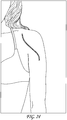
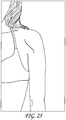
- this inset implant can be performed through a more limited mini-incision technique.
- a mini-deltopectoral incision is utilized. The skin incision is shorter, and the pectoralis tendon is left intact. The majority of the inferior capsule is also left intact. The glenoid labrum can be left intact if this is preferred by the surgeon. The central portion of the glenoid bone is then reamed while leaving the peripheral cortex intact.
- a method for implanting such glenoid implant for precise placement in the scapula and precise drilling and reaming of the scapula.
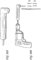
- the method is performed using a specialized power drill having a lateral drilling attachment and a short drill bit incorporated into the attachment, which is used to drill a central hole in the glenoid surface.
- the bone is then reamed with a reamer bit attached to the drill.
- the lateral drilling attachment inclines the axis of the drill relative to the axis of the access pathway by an angle within the range of from about 45° to about 110°, often within the range of from about 50° to about 90°, and, in one implementation about 60°.
- a slim design power drill for preparing a glenoid for implantation of a glenoid implant
- the power drill includes a right angle drilling attachment having an extension rod with a length of at least 10 cm, more preferably at least 12, 15, or 18 cm long, the end of which is includes a collet or chuck that is positioned at a 90° angle relative to the extension rod and which is adapted to receive a short drill bit; the power drill being prepared for use in the surgical field by sterilization.
- the drill and accessories can be sterilized and provided in a sterile container.
- the drill bit can be 10 mm long, more preferably 12, 14, 16, 18, or 20 mm long, and most preferably 25, 35, 45, 55, 65, or 75 mm long.
- the drill bit can have the following diameters: 1.5 mm, 2.5 mm, 3.0 mm, 3.2 mm, 4.0 mm, 4.5 mm, 5.0 mm, 5.5 mm, 6.0 mm, 6.5 mm, 7.0 mm, 8.0 mm, 9.0 mm, or 10.0 mm.
- the power drill is designed to allow drilling in spaces as tight as 50 mm.
- the overall length of the right angle drilling attachment can be 18 cm, more preferably 20 cm, most preferably 22 cm.
- the head width and extension rod diameter are preferably less than 25 mm, more preferably less than 22 mm, and most preferably less than 20 mm.
- the head length is preferably less than 30 mm, more preferably less than 28 mm, and most preferably less than 25 mm.
- the right angle drilling attachment can be designed to be attached to any power drill, the use of which is acceptable in a surgical field, and is designed to be lightweight, e.g., less than about 200 grams, more preferably less than about 180 grams, and most preferably less than about 150 grams.
- the power drill can be powered using a battery supply (cordless) or it can be powered using an electrical cord powered from a standard electrical outlet. See, e.g., U.S. Pat. No. 6,037,724 .
- the design of the glenoid implant of the invention provides increased implant fixation strength to glenoid bone and therefore decreases the rate of glenoid implant loosening.
- This implant is also designed for use in cases of deficient glenoid bone which would preclude the use of a current glenoid implant since they require adequate bone in the glenoid vault to support multiple long pegs or a keel.
- a humeral implant which is less than 70 mm in length, preferably about 60 mm in length, and is less than 40 mm wide from anterior to posterior (preferably 20-30 mm).
- the humeral implant is significantly shorter and thinner (in the anterior to posterior dimension) than most current stems, which are about 70-115 mm in length and bulkier in the proximal (metaphyseal) area than distally both in the anterior to posterior dimension and medial to lateral dimension. Because the humeral implant is shorter, it can be implanted in a narrower metaphyseal area and does not require the removal of a significant amount of bone.
- Fixation of the present humeral implant depends upon good interference fixation in the medial-lateral plane when press fit (similar to some current total hips).
- the humeral implant can be fixed using a bone cement, such as polymethylmethacrylate (PMMA) or a compatible fixation material.
- PMMA polymethylmethacrylate
- the humeral implant can be press-fit.
- a minimal incision shoulder arthroplasty technique that allows replacement of the glenoid surface and humeral head with only a small incision and less extensive soft tissue stripping.
- the "mini-incision” procedure also leaves the pectoralis tendon and the majority of the inferior capsule intact.
- the glenoid labrum can also be left intact.
- the central portion of the glenoid bone is then reamed while leaving the peripheral cortex intact.
- the advantages of this "mini-incision" procedure include a shorter incision with less scarring, increased safety, and a more simple exposure of the glenoid, thus allowing general orthopedists to perform a shoulder replacement with less difficulty and potentially fewer complications.
- the glenoid implant of the invention lacks a keel and multiple long pegs, which are typically present in the prior art glenoid implants. Instead, the glenoid implant of the invention includes one peg or flange disposed radially symmetrically about a central axis of the implant, such as only a single short (less than about 8 mm), central backside peg which stabilizes the glenoid implant.
- the glenoid implant of the invention does not require a long extended keel or long peg because the majority of the fixation strength is concentrated on the rim of the embedded implant. This obviates the need for significant backside fixation.
- the fixation offers circumferential cortical bone fixation around the prosthesis. The shear stresses placed on the implant are therefore supported by a circumferential buttress of bone, which is more mechanically sound than an onlay prosthesis with an extended backside keel or multiple long pegs.
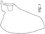
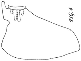
- An object of the invention is to minimize the common complications of glenoid implant loosening and fatigue failure that exist with current glenoid implants. All previous glenoid implants sit on the surface of a reamed articular surface and utilize a keel or multiple pegs to secure the implant inside the glenoid vault (see, e.g., FIGS. 3-6 ).
- This invention features a glenoid implant (which can be polyethylene, metal, ceramic, or combinations thereof) that is not designed to be placed on the surface of the reamed glenoid articular cartilage. Rather, the present implant is designed to be inset partially (e.g.
- the implant may be press fit or cemented in the reamed cavity within the glenoid bone.
- Patients who can benefit from the use of the glenoid implant of the invention include young, middle, and older patients with arthritis (typical total shoulder replacement (TSR) patients) or damage or injury to the shoulder.
- This new inset glenoid implant allows TSR surgery for new, previously contraindicated applications, including applications in which the patient presents with bone defects on the glenoid.
- the glenoid implant of the invention can also be utilized in revision surgeries.
- a glenoid implant 10 which is intended to be implanted in the glenoid as part of a TSR arthroplasty.
- Glenoid implant 10 replaces the natural glenoid cavity (see G of FIG. 15 ) and provides a bearing surface against which the head of a humerus or humeral component may articulate.
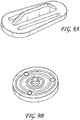
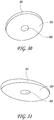
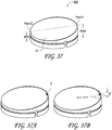
- Glenoid implant 10 includes concave articulating surface 14 and convex or flat backside surface 16, which can, optionally, include roughened or textured surface 18.
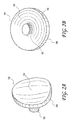
- Glenoid implant 10 can be provided as a circular design ( FIG. 1A and 1C ) or as an oblong, oval design (FIG. IB).
- glenoid implant 10 can include short, backside peg 12 on the medial, convex or flat backside surface 16 of glenoid implant 10.
- Short, backside peg 12 is situated centrally on the medial (back) side of glenoid implant 10 and is preferably a cylindrical peg shape that extends outwardly from glenoid implant 10 away from the back of the implant 16.
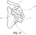
- Glenoid implant 10 including or excluding short, backside peg 12, is adapted to be implanted in a prepared cavity of the glenoid (see, e.g., FIG. 12 ), such that it is partially or fully inset to the cortical bone of the glenoid, and is retained with bone cement or using press-fit techniques. Glenoid implant 10 can be further secured to the glenoid using one or more screws.
- Glenoid component 10 includes concave lateral articulating surface 14 against which the head of a humerus or humeral component moves.
- Glenoid implant 10 is manufactured using a suitable material, for example, polyethylene, metal, ceramic, or combinations thereof, with lateral articulating surface 14 being smoothly contoured.
- the radius of curvature of the articulating glenoid surface can match the humeral head surface or it can be slightly larger than the radius of curvature of the humeral head implant.
- Glenoid implant 10 can have a lateral articulating surface 14 having a concave circular or oval surface encircled by circular edge 20.
- the implant at the circular edge 20 has a thickness in an axial direction in the range of about 3-6 mm, preferably about 3 mm.
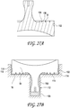
- the peripheral edge will have a greater axial dimension such as illustrated in FIG. 32 which includes an additional axially extending annular flange.
- glenoid implant 10 The medial, back side of glenoid implant 10 is preferably roughened or textured.
- glenoid implant 10 can include a series of elongated groves 18 in multiple locations for receiving bone cement to assist in the cement augmentation and retention of glenoid implant 10.
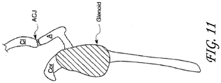
- the glenoid In preparing the glenoid to receive glenoid implant 10, the glenoid (G; see, e.g., FIG. 12 ) is reamed to receive all or a portion of glenoid implant 10 so that glenoid implant 10 is circumferentially surrounded by cortical bone of the glenoid (G), which aids in the stabilization and security of glenoid implant 10.
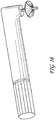
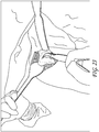
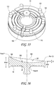
- FIGS. 13-16 there will be described a method for preparing a cavity in the glenoid for receiving a glenoid implant of the present invention and apparatus to be used therewith.
- the surgeon will initially determine the position of the drill site using a guide known in the art (see, e.g., U.S. Pat. Nos. 6,712,823 ; 6,364,910 ; 5,030,219 ; and 5,489,310 ).
- a reamer of appropriate size is then chosen based on the size of the sizer guide previously chosen.
- the reamer has a symmetrical head with a plurality of cutting blades and may have a peripheral stop surface.
- the previously drilled hole is used as a center guide for the reamer.
- the reamer is used to create a cavity in the glenoid surface of the scapula in which the prosthetic glenoid component will be installed.
- the reamed cavity is a receiving cavity for the glenoid repair device and is of a geometry that is generally complimentary to the geometry of the medial and peripheral aspects of the glenoid repair implant.
- the glenoid repair device is installed within the reamed bone cavity, with or without the use of bone cement. Insertion may be achieved by manually placing the repair device through the incision into the cavity within the bone or by means of an elongated insertion device so as to permit easy location, guidance and manipulation of the repair device through the incision and into and within the reamed bone cavity
- a method for implanting glenoid implant 10 will now be described with reference to FIGS. 13-16 . Initially, if a total shoulder arthroplasty is performed, a humeral implant having a head portion, discussed below, and a glenoid implant are implanted. Prior to implantation of the humeral component into the humerus, glenoid preparation begins.
- an alignment or pilot hole is first drilled substantially in the center of the glenoid cavity (G) using, e.g., the drill shown in FIGS. 14 , 15 , and 26 .
- the pilot hole is drilled, the glenoid cavity (G) is reamed using a glenoid surface rasp (see bit attached to the drill depicted in FIG. 16 ) attached to a reamer shaft with a driver having a laterally directed (e.g. 90°) distal end (see FIG. 26 ).
- the glenoid surface rasp may include a guide pin and a roughened cutting surface to create a trough for the glenoid component.
- the 90° angle of the shaft of the driver permits drilling in tight glenoid cavities. Thus, the procedure can be performed in a minimally invasive manner because it does not require full circumferential exposure of the glenoid, nor does it require a complete capsular release.
- the 90° shaft of the drill includes a quick-connect attachment which receives the quick-connect drill bit.
- the reamer is rotated by suitable power means or by hand to ream the glenoid cavity. Following such reaming, the reamer and the guide wire/drill are removed leaving a cavity which is wholly contained within the glenoid cavity (G).
- a confirmation step is performed in which a provisional or surrogate glenoid implant (often called "a trial") may be used prior to cementing the final glenoid implant to verify placement, range of motion, and glenoid size, and to verify that the glenoid implant is sufficiently inset within the bone.
- a provisional or surrogate glenoid implant (often called "a trial") may be used prior to cementing the final glenoid implant to verify placement, range of motion, and glenoid size, and to verify that the glenoid implant is sufficiently inset within the bone.
- Several iterations of this step may occur, in which various surrogate implant devices are tested in-vivo in order to select a preferred implant geometry. After the preferred glenoid implant has been selected, the surrogate implant is removed.
- a suitable bone cement such as polymethylmethacrylate (PMMA) or other compatible material, is placed in the reamed bone cavity of the glenoid vault and may also be applied to the medial (back) surface of glenoid implant 10.
- Glenoid implant 10 is then positioned within the prepared cavity. If a cemented construct has been chosen, the glenoid implant 10 is then held in place until the cement hardens to assure strong fixation of glenoid implant 10 in the scapula. The head portion of the humerus or humeral component may then engage the concave articulating surface of the glenoid implant 14.
- the reaming is contained completely within the boundary of the glenoid cavity (G) and therefore does not destroy the peripheral margin of the glenoid surface. Additionally, as can be seen in FIG. 7 , there is preferably a slight overhang of glenoid implant 10 beyond the margin of the natural glenoid cavity.
- This method can be performed using a deltopectoral or anterolateral surgical approach.
- glenoid implant 10 in the shoulder arthroplasty procedure allows the surgeon to use a "mini-incision technique," similar to techniques utilized for total knee surgery and total hip surgery. Typical incision sizes for current Glenoid repair procedures are in the range of 150 mm to 200 mm, use of the methods and devices disclosed herein permits a typical incision size in the range of 70 mm to 100 mm to be used. Further, the use of the glenoid implant 10 reduces the number of surgical steps, entries into the wound and has other surgical benefits as outlined in Table 1.
- the glenoid reaming and insertion of the glenoid trial and/or final glenoid implant as described herein may be accomplished via an incision of no more than about 100 mm, preferably no more than about 90 mm and more preferably no more than about 80 mm.
- Table 1 Comparison of surgical procedures for Current and Less Invasive Glenoid Replacement Standard surgical approach Less Invasive Glenoid approach, Incision size 15-20 cm 7-10 cm Deltopectoral incision Yes Yes Yes Subscap incision Yes Yes Yes Capsule wide excision Yes No (only incision of capsule) Labral incision Yes No Biceps release Yes Only if needed Full inferior capsule incision Yes No - partial Axillary nerve dissection-mobilization Yes No
- the medial aspect of a glenoid implant device 10 is shown.
- the device is substantially circular in design, having a radius in the range of about 22 to about 46 mm.
- the central anchor peg shown has a concave surface 51 disposed to receive a volume of bone cement so as to enhance adhesion and retention of the implant.
- Alternate configurations of this concave feature may include a plurality of annular ridges or grooves or other negative impressions in the exterior surface of the peg.
- the medial surface 16 of the implant device has been configured to facilitate the flow of bone cement across and around the medial and circumferential aspects of said device so as to attain enhanced adhesion and stability of the glenoid implant after insertion into the reamed cavity in the glenoid bone.
- the medial surface 16 has therein a plurality of concentric grooves 18, and a plurality of radial flow channels 120 disposed to interconnect the concentric grooves forming a continuous flow path between each of the concentric grooves.
- the interconnecting channels 120 on the medial surface are further connected to one or more circumferentially disposed channels 102 via the radial flow channels 120, thereby forming an open continuous flow pathway from the central anchoring peg 12, across the medial surface of the device 16 to and around the perimeter wall 20 of the glenoid implant device.
- This interconnected system of concentric grooves 18, radial flow channels 120 and circumferential channel 102 is designed to accommodate the flow of bone cement across the medial surface and around the circumference of the glenoid implant device so as to assure enhanced adhesion of the implant device to and within the reamed glenoid cavity in the bone.
- bone cement wells 100 on the medial aspect of the implant device 16. These wells 100 may be used in conjunction with the interconnected system of grooves 18 and radial flow channels 120 to accommodate and accept any excess bone cement material which may migrate while the glenoid implant device is being compressively inserted into the reamed cavity in the glenoid bone.
- FIG. 27A illustrates flow channels with such a negative taper geometry. As illustrated in FIG. 27A , the width of the channel at an opening 104 is less than the width at the bottom of the channel 106. This enables the strength of the bond between the bone cement and the implant to be a function of both the adhesive bonding capabilities of the cement as well as the mechanical interlocking provided by the negative taper.
- the bone cement 700 following implantation of the glenoid implant 10 will assume a concave configuration in which a first surface corresponds to the medial surface of the implant 10, and a second surface will assume the configuration of the reamed glenoid cavity.
- the bone cement shell will typically have a first layer 108 extending across the distal end of the central anchoring peg 12.
- the first layer 108 is connected via tubular wall 112 to a second layer 111.
- the radially inwardly facing surface of tubular wall 112 will preferably be provided with at least one interlocking engagement structure such as a radially inwardly extending annular ridge (as illustrated) which interlocks with the complementary annular concavity 51 illustrated in FIG. 27 .
- the second layer 111 generally comprises at least one surface structure 114 such as an annular ridge having a complementary configuration to the at least one annular concentric groove 18.
- the outer periphery of the second layer 111 is substantially circular in configuration, and carries an outer peripheral annular flange 116.
- Outer peripheral flange 116 may be provided with at least one radially inwardly directed projection or ridge 118, such as an annular ridge having a complementary configuration to one or more radially inwardly extending annular channels 102 on the perimeter surface 20 of the glenoid implant device.
- the hardened cement thus takes on the configuration of a concave shell, which corresponds to the mismatch in size and configuration between the surface of the implant and the complementary reamed surface of the glenoid bone.
- the thickness of the cement shell may vary, potentially down to zero in spots, depending upon placement and size of the implant relative to its corresponding reamed cavity in the glenoid bone.
- Fig 27B is an illustration demonstrating the adhesion and encapsulation of the glenoid repair implant device 10 within the reamed bone cavity, further illustrated is the bone cement 700, the bone cement adhering to or encapsulating the anchor peg 16, the medial surface of the implant device 16 and the perimeter groove 102.
- FIG. 30 illustrates a cavity reamed within glenoid bone, having a reamed surface 203 for engaging the medial aspect of a glenoid repair implant and a perimeter wall 201 completely surrounding the reamed surface 203 for the purposes of circumferentially engaging the complimentary perimeter aspect of said repair implant, thereby encircling and constraining the implant in the reamed bone cavity.
- FIG. 31 illustrates such a cavity reamed into the glenoid structure of a patient having worn, degenerated or otherwise deficient bone. In this instance there may be insufficient native bone to create a fully enclosed cavity within the bone tissue. As a consequence the reamed surface 203 may not be completely surrounded by the perimeter wall 201. As a result, there may be insufficient native boney structure to assure positive location or fixation of the glenoid repair implant within the reamed bone cavity.
- the medial surface of the device 16 has thereon an axially extending bone engagement structure 110.
- This structure may be a continuous annular construct such as an axially extending circumferential flange or may be an interrupted or castellated construct as shown.
- the engagement structure 110 will be symmetrically disposed about the circumference of the implant 10 so that the implant may be positioned without regard for its rotational orientation within the bore.
- the axially extending bone engagement structure 110 may be provided around less than the entire circumference, such as no more than about 270°, or no more than about 180° of the circumference of the implant.
- the axial length of the sidewall which includes both engagement structure 110 and the thickness of the implant at the peripheral edge will generally be at least about 3.5 mm, generally no more than about 18 mm and typically within the range of from about 4.5 mm to about 12 mm.
- the illustrated engagement structure 110 is positioned at the peripheral edge of the implant 10. However, the bone engagement structure 110 may be spaced radially inwardly from the outer peripheral edge of the implant 110.
- the engagement structure 110 will comprise either a single annular ridge, or a plurality of projections. See, e.g., FIG. 35 . In either event, the engagement structure will generally reside in a concentric circular orientation having a constant radius of curvature from the longitudinal axis of the implant. This permits convenient installation of the implant within a recess formed by a reaming tool having a rotational axis of symmetry.
- a second or a third or additional axially extending bone engagement structures 110 may also be provided, spaced radially inwardly from the illustrated annular flange.
- the reamed bone cavity has a reamed surface 203 disposed to engage the medial surface of the glenoid repair implant.
- This surface is further provided with a receiving groove 204 reamed below the plane of the surface 203 to receive the peripheral anchor 110 of the glenoid repair implant (see Fig 32 ).
- the groove within and below the surface of the bone tissue may be produced by reaming, either by means of a reamer tool having a complimentary cutting profile which simultaneously produces the surfaces 203, 205, 206 and 207 or by means of 2 reamers, one which produces surface 203, and another which subsequently produces surfaces 205, 206 and 207.
- the engagement of the perimeter construct 110 of the glenoid repair implant ( FIG. 32 ) with the receiving bone groove 204 within the glenoid bone structure enables complete circumferential engagement of the implant repair device within the glenoid bone structure to assure positive location and engagement of the implant device with and within the native bone tissue.
- the glenoid repair implant may be fixed to and within the reamed cavity by means of bone cement or other fixation means.
- a glenoid implant can be placed through the graft wedge.
- This procedure is extremely difficult to perform, even by highly skilled surgeon, there is a high degree of subjectivity and the rate of complications is high.
- Complications may include implant loosening, screw breakage or loosening, graft resorption, neurovascular injury and death.
- a glenoid implant device which can be implanted in a minimally invasive manner into bone deficient patients which allows for the restoration of natural angulation and geometry at the humerus to glenoid interface, does not require the use of bone graft material and does not require the use of a long keel or anchor peg system.
- a glenoid repair implant device having a generally cylindrical perimeter concentrically disposed about a central axis which is coincident with centerline CL.
- a medial surface 16 is configured to contact a reamed surface within glenoid bone and a concave articulating surface 14 is configured to contact the articulating surface of a humeral bone, or humeral bone prosthesis.
- the 'plane' of the articulating surface 14 is offset from the plane of the medial surface 16 by an include angle A, resulting in a wedge shaped cylindrical form.
- Angle A represents the corrective angle necessary to restore the functional angulation of the concave glenoid articulating 14 surface with respect to the reamed surface of the cavity within the bone tissue (203) of FIG. 30 .
- Angle A is generally within the range of 5 degrees to 30 degrees.
- the position of the neutral or resting position of the humeral to glenoid interface, Point R, may be adjusted by varying the nominal thickness of the implant device, d3. This thickness is typically in a range of 3 mm to 15 mm, depending upon the extent of the deficiency of native bone and the corrective angle necessary to restore functional angulation to the glenoid joint.
- FIG. 36 shown is a center section view through a circular glenoid implant.
- the section view shows the maximum height of the implant Dmax and the minimum height of the implant Dmin, both measured from a common reference such as the medial surface of the implant device 16.
- the medial surface 16 is perpendicular to the centerline of the implant device CL.
- the 'plane' of the articulating surface 301 is offset from the plane of the medial surface 14 by the corrective angle A.
- the offset angle of the plane of the articulating surface, angle A is defined as the maximum angle created by the intersection of a perpendicular 302 to the centerline of the device CL and the chord line 304 produced by connecting point P and point Q.
- Points P and Q are the respective maximum and minimum thickness dimension of the implant, measured in an axial direction, at their respective maximum radial distances from the device centerline CL, as measured from a constant reference such as the medial surface of the implant device 16.
- FIG. 37A illustrates a single indicator mark on the articulating surface and/or the peripheral edge of the implant, which indicates the apex of the articulating surface, point P.
- FIG. 37B illustrates a plurality of indicia radially orientated around the perimeter of the device, allowing for metered in-vivo rotational adjustment of the device to orient the apex of the implant at the optimal position within the reamed glenoid cavity.
- Indicia markings may be manufactured by many processes which produce a positive or negative feature on the device or which produce a graphic on or within the device, including but not limited to, laser marking, printing, injection molding and machining.
- the articulating surface 14 is defined as a surface of revolution created by rotating an arc of constant radius R1 about an axis of rotation 400, this axis of rotation being offset from the centerline of the device CL by angle A and intersecting the centerline of the device CL at a prescribed distance from the medial surface D3.
- the radius of the arc of rotation has an origin (0) located on the axis of rotation, thereby producing a spherical articulating surface.
- a line drawn perpendicular to the axis of rotation 400 at the articulating surface 14 (e.g., a tangent) will be angularly inclined relative to the centerline by an Angle A.
- Angle A may be at least about 5°, 10°, 15°, or 20° or more, depending upon the desired clinical performance.
- the origin O of the constant radius arc is offset contra-laterally from the axis of rotation 400 of the concave surface.
- the articulating surface is defined as a surface of revolution, created by sweeping an arc of constant radius (R1) about the axis of rotation 400 to produce a non spherical articulating surface of constant radius R1.
- FIG. 40 is a side elevational cross sectional view of the articulating surface created by the geometrical construct of FIG. 39 , illustrating that the surface construct has an apex at point R.
- 41 is a specific embodiment of this construct for a glenoid implant having a cylindrical diameter of 31 mm, the radius of the arc of revolution being 90 mm and being offset contra-laterally from the axis of rotation by 7.78 mm to produce a concave articulating surface with a depth of 3 mm at the device centerline.
- glenoid implants in accordance with the present invention will often have a lateral offset distance within the range of from about 2 mm to about 18 mm, and a radius for the arc of revolution within the range of from about 30 mm to about 200 mm and have a circular diameter of 20 mm to 55 mm.
- FIG. 42 is a perspective view showing a cross section through an articulating surface generated by the specific geometry of FIG. 41 , the plane of the articulating surface 14 being offset from the plane of the medial surface 16.
- FIG. 42 further shows the articulating surface generated by the specific construct of FIG. 41 and identifying the axis of rotation (400), the device centerline CL, the articulating surface of constant radius (R1) created by revolving this arc 360 degrees about the axis of rotation (400) and the resultant apex of the articulating surface, occurring at Point R.
- a constrained system is a specific combination on a prosthetic humeral head and glenoid implant pair, wherein there is a precise and constrained fit between the humeral head and the glenoid implant device, limiting relative motion of the two components to pure spherical articulation.
- the spherical diameters of the humeral head prosthesis and that of the glenoid implant device are deliberately mismatched, the glenoid implant having a larger diameter than the humeral head.
- the humeral head can articulate spherically and can translate across the surface of the glenoid implant in an unconstrained manner.
- US patent application 6,875,234 to Lipman et al. discloses a system wherein the glenoid articulating surface is comprised of 2 non tangential radii, the radius in the central neutral zone being larger than that of the humeral head and the glenoid radius lateral to the neutral zone being of a smaller size and being non-tangential to the radius of the neutral zone.
- the humeral head is free to articulate and translate within the central neutral zone and becomes more constrained as the humeral head translates laterally across the glenoid surface.
- FIG. 43 there is illustrated an enlarged cross sectional view of the articulating surface of the glenoid repair implant construct shown in FIG. 41 .
- FIG. 43 further illustrates a representation of various diameter humeral heads, ranging in size from 20 mm to 60 mm engaging the articulating surface 14 of the glenoid repair implant device 10. Humeral heads in current use range from 36 mm to 60 mm.
- FIG. 43 illustrates that the geometry of the articulating surface resulting by generating a surface of revolution in a manner described by FIG. 41 can accommodate a humeral head of any size. Further, this offset surface geometry construct results in full circumferential contact between the humeral head and the glenoid articulating surface while in the neutral position.
- FIG. 43 further illustrates a representation of various diameter humeral heads, ranging in size from 20 mm to 60 mm engaging the articulating surface 14 of the glenoid repair implant device 10. Humeral heads in current use range from 36 mm to 60 mm.
- chords C20, C40, C50 and C60 which are the diameters of the circumference of contact between the articulating surface of the glenoid repair device and the corresponding humeral heads having diameters measuring 20 mm, 40 mm, 50 mm and 60 mm respectively.
- This circumferential contact 1) increases the surface area of contact between the glenoid surface and humeral head implants significantly, as compared to an unconstrained system with a single point of contact; 2) results in a uniform circular distribution of loads within and through the glenoid implant; 3) distributes loads more uniformly around the central anchor peg so as to minimize offset loads which can loosen the implant; and 4) induces the humeral head to return to the neutral position after any translational movement across the articulating surface 14, resulting in an implant system with self centering characteristics.
- the geometry of the articulating surface 14 clearly demonstrates an apex of non-contact at Point R.
- the offset surface geometry construct there is never contact between the humeral head or the glenoid articulating surface 14 in an area of the surface surrounding point R, thereby creating a zone of non-contact having a diameter approximately equal to the chord length discussed above which depends upon the curvature of the humeral head.
- the articulated surface of the glenoid implant could be discontinuous in this region, allowing for the inclusion of a port or hole passing through the glenoid articulating surface into the central anchor peg to accommodate secondary fastening or securement of the implant device in the final in-vivo location.
- Such fasteners could include bone screws, staples, expanding pegs or other axially or rotationally adjustable devices which induce mechanical engagement to the native bone.
- This construct offers substantial advantage over current devices in which there is contact between the humeral head and any discontinuity in the articulating surface.
- FIG. 43A and 43B illustrate exemplary embodiments of one such construct.
- FIG. 43A illustrates a glenoid repair device which does not have an integral central anchor peg.
- the peg is replaced by a removable mechanical fastener 650 such as a bone screw, barbed peg, staple or other device which is inserted through the central access channel into the native glenoid bone passing from the articulating surface 14 through the medial surface 16 and into the native bone structure after the repair implant has been inserted into the reamed receiving cavity in the bone.
- a removable mechanical fastener 650 such as a bone screw, barbed peg, staple or other device which is inserted through the central access channel into the native glenoid bone passing from the articulating surface 14 through the medial surface 16 and into the native bone structure after the repair implant has been inserted into the reamed receiving cavity in the bone.
- a medial aspect of the glenoid repair implant device is shown.
- a segmented central anchor peg is shown, having an annular construct with a hollow core 132 and the annular aspect being divided into a plurality such as two or three or four or more discrete axially extending finger elements 130.
- the external diameter of the anchor peg (E) is larger than the internal diameter of the corresponding receiving hole drilled in the native glenoid bone.
- the finger elements 130 flex elastically radially inwardly into the hollow core 132 producing a radially outwardly directed compression force to be exerted in the native bone tissue.
- Such a segmented construct can be mechanically enhanced and complimented by a mechanical feature which engages the finger elements or native bone within or through the hollow core 132.
- the exemplary embodiment illustrated in Fig 43B has an open access channel 600 between the articulating surface 14 and the medial surface 16 of the device and further passing axially through the segmented central anchor peg, the segmented anchor peg being of a construct similar to that illustrated in Fig 32 .
- a mechanical fastener 601 is inserted in an axial direction through the opening of the central access channel 600 at the articulating surface of the implant device 14, engaging the internal surfaces of the anchor peg segments 610.
- the anchor peg segments 130 are induced to flex radially outwards causing the external surfaces of the anchor peg segments 620 to impinge into the native cancellous bone of the glenoid structure below the cortical bone surface.
- This impingement anchors the implant within the native bone of the glenoid structure.
- the radially outwardly facing surfaces of the segments 620 may be provided with any of a variety of barbs, ridges, roughened surface textures or other bone engagement feature.
- the mechanical fastener illustrated in Fig 43B is a threaded device, having an external thread 630 which mates with an internal thread 640 within the glenoid implant device.
- Variations of the mechanical fastener 601 may be used, including but not limited to, screws, barbed rods and split pegs.
- the mechanical fastener 601 includes a proximally facing surface 650, which, following installation, will face the humeral ball.
- Surface 650 is preferably recessed beneath the adjacent articulating surface 14. This may be accomplished by providing a recess 652 into the articulating surface 14 to receive a head on which the surface 650 resides.
- the mechanical fastener 601 may comprise a threaded body having a relatively constant outside diameter throughout its axial length, such that it can be axially advanced into the access channel 600 until the proximally facing surface 650 is beneath the level of articulating surface 14.
- the proximal surface 650 is provided with a mechanical interfit coupling, for removably cooperating with a driver tool.
- the coupling may comprise a recess such as slot or polygon such as a triangle, square, pentagon or hexagon.
- Implants in accordance with this aspect of the invention may be provided in a kit which includes a driver tool, such as an Allen wrench, or other specialized screwdriver to rotationally engage the mechanical fastener 601.
- the driver tool may comprise an elongate tubular body, having a lateral bend such as a 90° bend at its distal end.
- a rotatable tip is carried by the distal end, and configured to complement the geometry of the engagement structure on mechanical fastener 601.
- the rotatable tip is connected via the central lumen to a proximal control, which may be rotated by the clinician to rotate the mechanical fastener 601 into place.
- Mechanical connection between the proximal control and the distal rotatable tip may comprise a flexible cable extending through the central lumen, or a torque rod which may be provided with suitable gears at the point of the bend to translate rotational force from the longitudinal axis of the tool to the transverse axis of the rotatable tip.
- any of a variety of structures may be utilized to convert axial proximal or distal movement, or rotational movement of an active engagement mechanism, to produce a radially outwardly directed advance of one or more bone engaging components carried by the post 12 , to facilitate bone engagement.
- FIG. 45 an alternate embodiment of the medial aspect of a glenoid repair implant device 16 is shown having yet another exemplary embodiment of a segmented central anchor peg construct.
- the central anchor peg has an external diameter F, within the range of from about 10 mm to 20 mm.
- the relatively wide anchor peg is intended to isolate and distribute the forces transmitted to the glenoid implant device by the humeral head while articulating within the normal neutral region of the shoulder joint.
- the segmented anchor peg of this embodiment may further be provided with a hollow core 132, capable of accepting and retaining supplemental bone graft material so as to promote osteointegration of the glenoid repair implant within the native bone.
- a hollow core 132 capable of accepting and retaining supplemental bone graft material so as to promote osteointegration of the glenoid repair implant within the native bone.
- Radially outwardly actuatable barbs, spikes or other bone engagement structures may also be provided as discussed above.
- diameter F of the glenoid repair implant ( FIG. 45 ) is larger than the maximum chord of contact which can occur for the corresponding humeral implant thereby assuring an optimal distribution of forces within the glenoid repair implant as a result of the circumferential line of contact and optimal transfer of loads through the glenoid repair implant into the native bone structure through the structure of the central anchor peg.
- humeral head cutting jig 26 is a simple, low profile humeral cutting jig that can be a full circle or part thereof. Cutting jig 26 can be secured to the humeral head using K-wires, pins, or screws 27 and is removed after completion of humeral head resection. Cutting jig 26 includes handle portion 28.
- the cutting jig should be placed along the anatomic neck of the humeral head. Osteophytes which obscure the junction of the humeral head and humeral shaft should be removed in order to accurately mark the level of the anatomic neck circumferentially from anterior to inferior to posterior.
- the cutting jig can be fixed to the humerus using wires, pins, or screws at the appropriate angle and version as determined by the surgeon.
- the rotator cuff should be carefully protected with retractors, and then the humeral cut is performed using an oscillating saw or osteotome along the surface of the cutting jig.
- the cutting jig can be manufactured using metal.
- humeral implant prosthesis 38 includes stem 40 having elongated portion 42 optionally including collar 44, which prevents humeral implant prosthesis 38 from embedding too deeply in the humerus.
- Humeral implant 38 also includes flange (fin) 46, which aids in the fixation of the stem in the humerus and prevents rotation of humeral implant in the humerus.
- the stem length is preferably less than about 70 mm, and the stem width is preferably less than about 40 mm (preferably about 30 mm).
- the support surface has an upper planar surface 50 that includes bore (hole with morse taper) 52 extending inwardly from the top plane thereof, and which is adapted to be engaged by a humeral head implant with a morse taper extension.
- Modular humeral head implants are known in the art (see, e.g., U.S. Pat. Nos. 4,865,605 ; 5,314,479 ; 5,462,563 , and 5,489,309 , and U.S. Patent Application Nos. 2004/0167629 , 2004/0064187 ).
- the plane of upper planar surface 50 is preferably between about 45 degrees and about 60 degrees to the axis of the stem.
- the entire stem portion, or a portion thereof, is preferably coated with a porous material for aiding in the fixation of the humeral implant in the humerus for a press fit stem.
- the implants made for cement fixation can have a smooth surface or a roughened, textured surface.
- Humeral implant 38 can be rectangular or rounded edges, but is significantly thinner anterior to posterior than medial to lateral. It will have a morse taper for securing a standard humeral head implant.
- humeral implant over current humeral implant stems is that the humeral implant disclosed herein is significantly shorter than most current stems, which are about 70-115 mm in length. Because the humeral implant is shorter, it saves bone because of the narrow metaphyseal area required for implantation.
- the present humeral implant is less than 70 mm in length, preferably about 60 mm in length, and less than 40 mm anterior-posterior width (preferably about 30 mm). Fixation of the present humeral implant depends upon good interference fixation in the medial-lateral plane when press fit (similar to some current total hips).
- the humeral implant can be fixed using a bone cement, such as polymethylmethacrylate (PMMA) or a compatible fixation material, or it can be press-fit.
- PMMA polymethylmethacrylate
- a total shoulder replacement using an inset glenoid implant of the invention and a standard humeral implant was performed.
- the smaller size and circumferential fixation of the inset glenoid implant allowed safe placement of the prosthesis within the confines of the patient's deficient glenoid cavity.
- the deficient glenoid vault was not fractured and the fixation was very stable.
- the patient had 100% relief of pain only 1 week after surgery.
- Her own assessment of shoulder function 4 weeks after surgery was 56% of normal (American Shoulder and Elbow Society validated outcome score [ASES score]) was 56 compared to 16% of normal before the surgery (ASES score 16).
- FIGS. 21-23 are intraoperative pictures of the implanted inset glenoid prosthesis in this patient.
Landscapes
- Health & Medical Sciences (AREA)
- Life Sciences & Earth Sciences (AREA)
- Orthopedic Medicine & Surgery (AREA)
- Surgery (AREA)
- Veterinary Medicine (AREA)
- General Health & Medical Sciences (AREA)
- Public Health (AREA)
- Engineering & Computer Science (AREA)
- Biomedical Technology (AREA)
- Heart & Thoracic Surgery (AREA)
- Animal Behavior & Ethology (AREA)
- Oral & Maxillofacial Surgery (AREA)
- Transplantation (AREA)
- Molecular Biology (AREA)
- Medical Informatics (AREA)
- Nuclear Medicine, Radiotherapy & Molecular Imaging (AREA)
- Cardiology (AREA)
- Vascular Medicine (AREA)
- Dentistry (AREA)
- Neurology (AREA)
- Physical Education & Sports Medicine (AREA)
- Prostheses (AREA)
Claims (5)
- Glenoidimplantat (10), umfassend einen kreisförmigen Körper mit:einer medialen Oberfläche (16);einer konkaven Gelenkfläche (14);einer kreisförmigen Umfangskante;einer zentralen Achse (CL);einem Stiel (12) auf der medialen Oberfläche (16), der konzentrisch zur Mittelachse (CL) angeordnet ist; undeinem Punkt (R), an dem die zentrale Achse (CL) die Gelenkfläche (14) schneidet,dadurch gekennzeichnet, dass der kreisförmige Körper ferner Folgendes umfasstmindestens einen sich axial erstreckenden Flansch, der sich von der medialen Oberfläche (16) an der Umfangskante des Rundkörpers erstreckt; wobeidie konkave Gelenkfläche (14) als eine Rotationsfläche definiert ist, welche durch das Schwenken eines Bogens mit konstantem Radius (R1) um eine Drehachse (400) zum Erzeugen einer nicht-kugelförmigen Gelenkfläche mit konstantem Radius (R1) erzeugt wird, wobei die Drehachse (400) von der Mittelachse (CL) um einen Winkel (A) versetzt ist und sich an dem Punkt (R) mit der Mittelachse (CL) schneidet, unddie konkave Gelenkfläche (14) so gestaltet ist, dass eine Kugel mit einem Durchmesser, die mit der konkaven Gelenkfläche (14) in Anlage gebracht wird, so dass die Mittelachse (CL) des Glenoidimplantats einen Mittelpunkt der Kugel schneidet, einen Kontaktkreis zwischen der Kugel und der konkaven Gelenkfläche (14) festlegt, wobei ein Durchmesser des Kontaktkreises kleiner als sowohl ein Durchmesser der kreisförmigen Umfangskante des Implantats als auch kleiner als der Durchmesser der Kugel ist, wobei die Kugel die konkave Gelenkfläche (14) innerhalb des Kontaktkreises nicht berührt.
- Implantat (10) nach Anspruch 1, wobei die konkave Gelenkfläche (14) gestaltet ist, um einen Kontaktkreis mit Kugeln mit einem Durchmesser zwischen 20 mm und 60 mm zu erschaffen.
- Implantat (10) nach Anspruch 1 oder 2, ferner umfassend einen zentralen Kanal (600) zwischen der Gelenkfläche (14) und der medialen Oberfläche (16), der ferner axial durch den Stiel (12) verläuft.
- Implantat (10) nach Anspruch 3, wobei der Stiel (12) ferner mindestens zwei Segmente (130) umfasst, die sich medial zwischen einer ersten Konfiguration, in der die mindestens zwei Segmente (130) zueinander benachbart sind, und einer zweiten Konfiguration bewegen können, in der die mindestens zwei Segmente (130) im Vergleich zur ersten Konfiguration weiter auseinanderliegen.
- Implantat (10) nach Anspruch 4, ferner umfassend ein mechanisches Befestigungselement (601), das zum axialen Einsetzen durch den Mittelkanal (600) der Gelenkfläche (14) und des Stiels (12) so angepasst ist, dass ein Einsetzen des mechanischen Befestigungselements (601) in den Mittelkanal des Stiels (12) die Segmente (130) des Stiels (12) zwischen der ersten Konfiguration und der zweiten Konfiguration bewegt.
Applications Claiming Priority (2)
| Application Number | Priority Date | Filing Date | Title |
|---|---|---|---|
| US12/719,182 US8778028B2 (en) | 2005-02-25 | 2010-03-08 | Methods and devices for less invasive glenoid replacement |
| PCT/US2011/027082 WO2011112425A1 (en) | 2010-03-08 | 2011-03-03 | Methods and devices for less invasive glenoid replacement |
Publications (3)
| Publication Number | Publication Date |
|---|---|
| EP2544632A1 EP2544632A1 (de) | 2013-01-16 |
| EP2544632A4 EP2544632A4 (de) | 2013-09-25 |
| EP2544632B1 true EP2544632B1 (de) | 2018-12-05 |
Family
ID=44563787
Family Applications (1)
| Application Number | Title | Priority Date | Filing Date |
|---|---|---|---|
| EP11753831.4A Active EP2544632B1 (de) | 2010-03-08 | 2011-03-03 | Schultergelenkersatz |
Country Status (4)
| Country | Link |
|---|---|
| US (5) | US8778028B2 (de) |
| EP (1) | EP2544632B1 (de) |
| AU (1) | AU2011224694A1 (de) |
| WO (1) | WO2011112425A1 (de) |
Families Citing this family (71)
| Publication number | Priority date | Publication date | Assignee | Title |
|---|---|---|---|---|
| US11957595B2 (en) | 2005-02-25 | 2024-04-16 | Shoulder Innovations, Inc. | Methods and devices for less invasive glenoid replacement |
| US8007538B2 (en) * | 2005-02-25 | 2011-08-30 | Shoulder Innovations, Llc | Shoulder implant for glenoid replacement |
| US8778028B2 (en) | 2005-02-25 | 2014-07-15 | Shoulder Innovations, Inc. | Methods and devices for less invasive glenoid replacement |
| US9545311B2 (en) | 2009-03-05 | 2017-01-17 | Tornier, Inc. | Glenoid implant anchor post |
| US8556901B2 (en) | 2009-12-31 | 2013-10-15 | DePuy Synthes Products, LLC | Reciprocating rasps for use in an orthopaedic surgical procedure |
| US8506569B2 (en) | 2009-12-31 | 2013-08-13 | DePuy Synthes Products, LLC | Reciprocating rasps for use in an orthopaedic surgical procedure |
| FR2967046A1 (fr) | 2010-11-10 | 2012-05-11 | Tornier Sa | Fraiseuse orthopedique de preparation osseuse, en particulier de preparation glenoidienne |
| US9381086B2 (en) | 2010-11-30 | 2016-07-05 | Shoulder Innovations, Llc | Stem for use in joint arthroplasty |
| US8486076B2 (en) * | 2011-01-28 | 2013-07-16 | DePuy Synthes Products, LLC | Oscillating rasp for use in an orthopaedic surgical procedure |
| FR2971144A1 (fr) | 2011-02-08 | 2012-08-10 | Tornier Sa | Implant glenoidien pour prothese d'epaule et kit chirurgical |
| US20120253467A1 (en) | 2011-02-13 | 2012-10-04 | Mark Frankle | Shoulder Arthroplasty Systems and Configurations for Components Thereof |
| US9763679B2 (en) | 2011-03-18 | 2017-09-19 | DePuy Synthes Products, Inc. | Combination driver/anti-rotation handle for shoulder arthroplasty |
| US9226830B2 (en) * | 2011-03-18 | 2016-01-05 | DePuy Synthes Products, Inc. | Device and method for retroversion correction for shoulder arthroplasty |
| US8551177B2 (en) | 2011-03-18 | 2013-10-08 | DePuy Synthes Products, LLC | Revision glenoid kit |
| US9820758B2 (en) | 2011-03-18 | 2017-11-21 | DePuy Synthes Products, Inc. | Combination reamer/drill bit for shoulder arthoplasty |
| US9364333B1 (en) | 2011-04-01 | 2016-06-14 | The Lonnie and Shannon Paulos Trust | Transosseous methods and systems for joint repair |
| US8663327B2 (en) * | 2012-02-06 | 2014-03-04 | Biomet Manufacturing, Llc | Modular junction seal of an orthopedic implant |
| US8696677B2 (en) | 2012-02-13 | 2014-04-15 | DePuy Synthes Products, LLC | Orthopaedic surgical saw assembly for removing an implanted glenoid component and method of using the same |
| AU2016201393B2 (en) * | 2012-02-13 | 2017-07-13 | DePuy Synthes Products, LLC | Orthopaedic surgical saw assembly for removing an implanted glenoid component and method of using the same |
| US9855065B2 (en) * | 2012-09-28 | 2018-01-02 | Depuy Ireland Unlimited Company | Orthopaedic surgical instrument assembly for implanting a prosthetic patella component |
| US8801796B2 (en) * | 2012-12-31 | 2014-08-12 | Richard A. Rogachefsky | Bone prosthesis for maintaining joint operation in complex joints |
| US10335163B2 (en) | 2013-03-05 | 2019-07-02 | Depuy Ireland Unlimited Company | Polymer 4-in-2 femoral cutting instrument having separable A/P and chamfer cutting blocks |
| US9814471B2 (en) | 2013-03-11 | 2017-11-14 | Catalyst Orthoscience Inc. | Glenoid arthroplasty and offset reamers |
| US11007063B2 (en) | 2013-03-11 | 2021-05-18 | Catalyst Orthoscience Inc. | Offset reamers |
| USD730522S1 (en) | 2013-03-11 | 2015-05-26 | Catalyst Orthopaedics Llc | Implant |
| US20170319348A1 (en) * | 2015-08-10 | 2017-11-09 | Catalyst Orthoscience Inc. | Arthroplasty prostheses with multi-axis fixation |
| US10973646B2 (en) | 2013-03-11 | 2021-04-13 | Catalyst Orthoscience Inc. | Stabilized drill guide |
| US9814588B2 (en) | 2015-08-10 | 2017-11-14 | Catalyst Orthoscience Inc. | Glenoid arthroplasty with multi-directional fixation |
| US9289306B2 (en) | 2013-03-15 | 2016-03-22 | Catalyst Orthopaedics Llc | Humeral arthroplasty |
| US10143556B2 (en) * | 2013-04-15 | 2018-12-04 | Eisurf IP-Managment AB | System of designing a guide tool and/ or surgical kit tools and/or an implant comprising a positioning mark |
| US20190231538A1 (en) * | 2013-04-15 | 2019-08-01 | Episurf Ip-Management Ab | Method of designing and positioning a medical implant and an implant comprising a positioning mark |
| US10433969B2 (en) | 2013-12-30 | 2019-10-08 | United Orthopedic Corp. | Arthroplasty implants and methods for orienting joint prosthesis |
| US9962266B2 (en) | 2015-09-11 | 2018-05-08 | Deltoid, Llc | Arthroplasty components |
| EP3777777B1 (de) | 2014-01-03 | 2023-04-05 | Howmedica Osteonics Corp. | Schultergelenkspfannenimplantat für schulterprothese |
| US20150289984A1 (en) * | 2014-04-15 | 2015-10-15 | Matthew D. BUDGE | Total Shoulder Arthroplasty Prosthesis |
| US9681960B2 (en) | 2014-05-16 | 2017-06-20 | Howmedica Osteonics Corp. | Guides for fracture system |
| US10575968B2 (en) | 2014-05-16 | 2020-03-03 | Howmedica Osteonics Corp. | Guides for fracture system |
| US11234826B2 (en) * | 2014-06-30 | 2022-02-01 | Howmedica Osteonics Corp. | Augmented glenoid components and devices for implanting the same |
| US10492926B1 (en) | 2014-09-04 | 2019-12-03 | Shoulder Innovations, Inc. | Alignment guide for humeral or femoral stem replacement prostheses |
| GB201505212D0 (en) * | 2015-03-26 | 2015-05-13 | Imp Innovations Ltd | Prosthetic glenoid component |
| US10342669B2 (en) | 2015-04-07 | 2019-07-09 | Zimmer, Inc. | Convertible glenoid |
| BR112017002731A2 (pt) * | 2015-04-17 | 2018-01-16 | Wright Medical Tech Inc | implante, sistema e método |
| US10722374B2 (en) | 2015-05-05 | 2020-07-28 | Tornier, Inc. | Convertible glenoid implant |
| USD835276S1 (en) | 2015-09-11 | 2018-12-04 | United Orthopedic Corporation | Keeled glenoid |
| US10335169B2 (en) | 2015-09-14 | 2019-07-02 | Symmetry Medical Manufacturing, Inc. | Angled orthopaedic driver |
| US10335282B2 (en) | 2016-02-09 | 2019-07-02 | Richard A. Rogachefsky | Magnetic joint replacement |
| WO2018017615A1 (en) * | 2016-07-18 | 2018-01-25 | Catalyst Orthoscience Inc. | Arthroplasty prostheses with multi-axis fixation |
| US10456262B2 (en) * | 2016-08-02 | 2019-10-29 | Howmedica Osteonics Corp. | Patient-specific implant flanges with bone side porous ridges |
| EP4520302A3 (de) | 2017-04-14 | 2025-04-16 | Shoulder Innovations, Inc. | Totalschulterprothese mit eingesetztem glenoidimplantat, das von anatomisch zu invers konvertierbar ist |
| US11510785B2 (en) * | 2017-04-25 | 2022-11-29 | Biomet Manufacturing, Llc | Augmented glenoid with groove |
| WO2019079104A2 (en) | 2017-10-16 | 2019-04-25 | Imascap Sas | SHOULDER IMPLANTS AND METHODS OF USE AND ASSEMBLY |
| WO2019213073A1 (en) | 2018-04-30 | 2019-11-07 | Shoulder Innovations, Llc | Inset/onlay glenoid, porous coated convertible glenoid, and humeral heads with textured undersides |
| US12295853B2 (en) | 2018-07-27 | 2025-05-13 | Depuy Ireland Unlimited Company | Implants, systems and methods of using the same |
| EP3829494B1 (de) * | 2018-07-27 | 2024-08-07 | DePuy Ireland Unlimited Company | Implantate |
| CN113645924A (zh) * | 2018-07-27 | 2021-11-12 | Ignite骨科有限责任公司 | 植入物、系统及其使用方法 |
| CN113613599A (zh) | 2019-03-11 | 2021-11-05 | 舒尔德创新有限公司 | 全反向肩部系统和方法 |
| USD977643S1 (en) | 2019-03-12 | 2023-02-07 | Shoulder Innovations, Inc. | Humeral stem implant |
| EP3968905A1 (de) | 2019-05-13 | 2022-03-23 | Howmedica Osteonics Corp. | Glenoidgrundplatte und implantatanordnungen |
| AU2020207869A1 (en) * | 2019-08-01 | 2021-02-18 | Howmedica Osteonics Corp. | Hybrid metal-backed glenoid component |
| WO2021030146A1 (en) | 2019-08-09 | 2021-02-18 | Tornier, Inc. | Apparatuses and methods for implanting glenoid prostheses |
| IT201900021432A1 (it) * | 2019-11-18 | 2021-05-18 | Limacorporate Spa | Componente glenoideo per protesi di spalla e relativa protesi di spalla |
| AU2021204625A1 (en) * | 2020-07-06 | 2022-01-20 | Howmedica Osteonics Corp. | Anatomic implant for joints |
| AU2021413348B2 (en) * | 2020-12-31 | 2024-09-12 | Howmedica Osteonics Corp. | Glenoid implants |
| US20240024119A1 (en) * | 2021-02-11 | 2024-01-25 | Howmedica Osteonics Corp. | Fixation mechanism for glenoid implants |
| EP4271291A4 (de) | 2021-02-26 | 2024-11-27 | Howmedica Osteonics Corp. | Glenoidimplantatkomponenten und instrumente dafür |
| WO2022232517A1 (en) * | 2021-04-29 | 2022-11-03 | Raphael S.F. Longobardi, Llc | Modular glenoid component for use in a universal shoulder prosthesis system |
| EP4351485B1 (de) * | 2021-08-12 | 2026-04-01 | Howmedica Osteonics Corp. | Mit fenstern versehene glenoidlagerkomponente |
| EP4496519A1 (de) * | 2022-03-21 | 2025-01-29 | University of Pittsburgh- Of the Commonwealth System of Higher Education | Chirurgischer bohrer für kraniosynostose und endoskopische verfahren |
| US12076025B2 (en) | 2022-05-11 | 2024-09-03 | DePuy Synthes Products, Inc. | Polymer cutting block |
| US12440344B2 (en) | 2023-09-21 | 2025-10-14 | Arthrex, Inc. | Constrained orthopaedic implants and methods of repair |
| CN117898776B (zh) * | 2024-02-21 | 2025-05-09 | 欣瑞德(江苏)医疗科技有限公司 | 一种单孔多通道穿刺器 |
Citations (1)
| Publication number | Priority date | Publication date | Assignee | Title |
|---|---|---|---|---|
| US6875234B2 (en) * | 2001-02-21 | 2005-04-05 | The New York, Society For The Ruptured And Crippled Maintaining Hospital For Special Surgery | Dual-radius glenoid prosthetic component for total shoulder arthroplasty |
Family Cites Families (216)
| Publication number | Priority date | Publication date | Assignee | Title |
|---|---|---|---|---|
| GB764438A (en) | 1954-01-29 | 1956-12-28 | Chevalier Et Fils E | Improved artificial femoral heads |
| FR2248820A1 (en) | 1973-10-29 | 1975-05-23 | Benoist Girard & Cie | Complete artificial joint between bones - has interlocked rings permanently attached together |
| US4012796A (en) | 1975-09-24 | 1977-03-22 | Howmedica, Inc. | Interpositioning collar for prosthetic bone insert |
| US3979778A (en) | 1976-01-14 | 1976-09-14 | Stroot Jerome H | Shoulder prosthesis |
| US4003095A (en) | 1976-04-29 | 1977-01-18 | Howmedica, Inc. | Trispherical prosthetic shoulder device |
| US4045826A (en) | 1977-02-09 | 1977-09-06 | Stroot Jerome H | Glenoid component for shoulder prosthesis |
| US4206517A (en) | 1977-12-01 | 1980-06-10 | Biomedical Engineering Corp. | Floating center prosthetic joint |
| US4261062A (en) | 1979-03-22 | 1981-04-14 | The Regents Of The University Of California | Natural shoulder joint prosthesis |
| CH642252A5 (de) | 1980-01-14 | 1984-04-13 | Sulzer Ag | Blattartiger schaft fuer die verankerung einer hueftgelenkprothese. |
| DE3216538A1 (de) | 1982-05-03 | 1983-11-03 | Waldemar Link (Gmbh & Co), 2000 Hamburg | Knochenimplantat, insbesondere femorale hueftgelenkprothese |
| US4990161A (en) | 1984-03-16 | 1991-02-05 | Kampner Stanley L | Implant with resorbable stem |
| JPS62500110A (ja) | 1984-06-12 | 1987-01-16 | キエフスキ ポリテヒニチェスキ インスティテュト イメニ 50−レティア ベリコイ オクトヤブルスコイ ソツィアリスティチェスコイ レボリュツィイ | 真空中でフィルムを蒸着させるための蒸発器 |
| FR2567019A1 (fr) | 1984-07-06 | 1986-01-10 | Fournier Gilles | Mode de contention des pieces d'une endoprothese articulaire |
| US4550450A (en) | 1984-07-24 | 1985-11-05 | Kinnett James G | Total shoulder prosthesis system |
| GB8520360D0 (en) | 1985-08-14 | 1985-09-18 | Thackray C F Ltd | Joint prosthesis |
| US5314479A (en) | 1986-08-15 | 1994-05-24 | Depuy Inc. | Modular prosthesis |
| US4827919A (en) | 1986-10-27 | 1989-05-09 | Pfizer Hospital Products Group, Inc. | Femoral spacer |
| DE8708419U1 (de) | 1987-06-15 | 1987-08-06 | Waldemar Link Gmbh & Co, 2000 Hamburg | Endoprothese |
| FR2618065A1 (fr) | 1987-07-15 | 1989-01-20 | Bourgogne Universite | Prothese totale de l'epaule |
| US4865605A (en) | 1988-02-02 | 1989-09-12 | Dines David M | Modular shoulder prosthesis |
| US5080673A (en) | 1988-02-03 | 1992-01-14 | Intermedics Orthopedics, Inc. | Glenoid prosthesis and method of use |
| US4964865A (en) | 1988-02-03 | 1990-10-23 | Intermedics Orthopedics, Inc. | Glenoid prosthesis and method of use |
| DE3813944A1 (de) | 1988-04-26 | 1989-11-09 | S & G Implants Gmbh | Endoprothese fuer ein gelenk |
| DE3816676A1 (de) | 1988-05-17 | 1989-11-23 | S & G Implants Gmbh | Schulterspan |
| US4986833A (en) | 1989-05-05 | 1991-01-22 | Worland Richard L | Glenoid component for an artificial shoulder joint |
| US5370694A (en) | 1989-07-25 | 1994-12-06 | Smith & Nephew Richards, Inc. | Zirconium oxide and nitride coated endoprostheses for tissue protection |
| US5030219A (en) | 1990-01-22 | 1991-07-09 | Boehringer Mannheim Corporation | Glenoid component installation tools |
| US5032132A (en) | 1990-01-22 | 1991-07-16 | Boehringer Mannheim Corporation | Glenoid component |
| GB2251795B (en) | 1991-01-17 | 1995-02-08 | Minnesota Mining & Mfg | Orthopaedic implant |
| GR1002517B (el) | 1991-09-30 | 1997-01-23 | Johnson & Johnson Orthopaedics Inc. | Προσθεση ισχιου. |
| JPH05326988A (ja) | 1992-05-19 | 1993-12-10 | Mitsubishi Electric Corp | 赤外線検出器 |
| DE4220217C2 (de) | 1992-06-20 | 1995-02-23 | S & G Implants Gmbh | Endoprothese |
| US5282865A (en) | 1992-06-22 | 1994-02-01 | Osteonics Corp. | Humeral shoulder prosthesis |
| US5344458A (en) | 1992-08-06 | 1994-09-06 | Bonutti Peter M | Arthroplasty component |
| GB9217639D0 (en) | 1992-08-19 | 1992-09-30 | Zimmer Limited | Acetabular prosthetic techniques |
| FR2695313B1 (fr) | 1992-09-08 | 1994-10-28 | Fabrication Etu Realisa Implan | Implant glénoïdien. |
| GB9221257D0 (en) | 1992-10-09 | 1992-11-25 | Minnesota Mining & Mfg | Glenoid alignment guide |
| US5358525A (en) | 1992-12-28 | 1994-10-25 | Fox John E | Bearing surface for prosthesis and replacement of meniscal cartilage |
| US5489309A (en) | 1993-01-06 | 1996-02-06 | Smith & Nephew Richards Inc. | Modular humeral component system |
| US5480450A (en) | 1993-02-11 | 1996-01-02 | The General Hospital Corporation | Method and apparatus for reducing interfacial porosity in a cemented femoral prosthesis |
| JPH06327705A (ja) | 1993-05-26 | 1994-11-29 | Kobe Steel Ltd | 人工関節 |
| US5507817A (en) | 1994-02-22 | 1996-04-16 | Kirschner Medical Corporation | Modular humeral prosthesis for reconstruction of the humerus |
| US5489310A (en) * | 1994-06-27 | 1996-02-06 | Mikhail; W. E. Michael | Universal glenoid shoulder prosthesis and method for implanting |
| US6290726B1 (en) | 2000-01-30 | 2001-09-18 | Diamicron, Inc. | Prosthetic hip joint having sintered polycrystalline diamond compact articulation surfaces |
| US5507819A (en) | 1994-11-02 | 1996-04-16 | Wolf; Eugene M. | Apparatus and method for stabilizing a humeral head in a shoulder |
| US5728161A (en) | 1995-06-08 | 1998-03-17 | Depuy Orthopedics, Inc. | Large taper modular shoulder prosthesis |
| ATE217174T1 (de) | 1995-08-25 | 2002-05-15 | Bristol Myers Squibb Co | Prothetisches implantat mit rippen |
| US5593448A (en) | 1995-11-14 | 1997-01-14 | Osteonics Corp. | Glenoid component for shoulder prosthesis and implant method |
| FR2741796B1 (fr) | 1995-11-30 | 1998-03-27 | Tornier Sa | Dispositif pour la fixation d'une prothese et notamment d'une prothese glenoidienne de l'omoplate |
| US5769856A (en) | 1996-06-24 | 1998-06-23 | Osteonics Corp. | Drill guide and implant method |
| US5746771A (en) | 1996-09-30 | 1998-05-05 | Wright Medical Technology, Inc. | Calcar collar instrumentation |
| US5800551A (en) | 1997-03-10 | 1998-09-01 | Biomet, Inc. | Apparatus and method for shoulder arthroplasty |
| US6037724A (en) | 1997-05-01 | 2000-03-14 | Osteomed Corporation | Electronic controlled surgical power tool |
| US5928285A (en) | 1997-05-30 | 1999-07-27 | Bristol-Myers Squibb Co. | Orthopaedic implant having an articulating surface with a conforming and translational surface |
| US6379386B1 (en) | 1997-09-09 | 2002-04-30 | Stryker Technologies Corporation | Anatomic glenoid shoulder prosthesis together with methods and tools for implanting same |
| GB9724280D0 (en) | 1997-11-17 | 1998-01-14 | Benoist Girard & Cie | Device to pressurise cement when implanting an acetabular cup |
| CA2263736C (en) * | 1998-02-28 | 2005-01-25 | Kraft Foods, Inc. | Food product dressings and methods for preparing food product dressings |
| US6228119B1 (en) | 1998-06-09 | 2001-05-08 | Depuy Orthopaedics, Inc. | Modular glenoid assembly |
| US6368353B1 (en) | 1999-02-24 | 2002-04-09 | Michel A. Arcand | Shoulder prosthesis apparatus and methods |
| EP1043001A3 (de) | 1999-04-07 | 2000-10-18 | Depuy Orthopaedics, Inc. | Kragenlose arthroplastische Schulterprothese |
| FR2794641B1 (fr) | 1999-06-09 | 2001-11-23 | Tornier Sa | Prothese humerale |
| FR2802799B1 (fr) | 1999-12-23 | 2002-08-16 | Depuy France | Ensemble de prothese d'epaule |
| US6709463B1 (en) | 2000-01-30 | 2004-03-23 | Diamicron, Inc. | Prosthetic joint component having at least one solid polycrystalline diamond component |
| US20040199260A1 (en) | 2000-01-30 | 2004-10-07 | Pope Bill J. | Prosthetic joint component having at least one sintered polycrystalline diamond compact articulation surface and substrate surface topographical features in said polycrystalline diamond compact |
| AU2001247476A1 (en) | 2000-03-16 | 2001-09-24 | Eugene M. Wolf M.D. Inc | Facile total shoulder arthroplasty apparatus and method |
| US6911047B2 (en) | 2000-03-17 | 2005-06-28 | Depuy Orthopaedics, Inc. | Apparatus and method for securing a cementless glenoid component to a glenoid surface of a scapula |
| US7618462B2 (en) | 2000-05-01 | 2009-11-17 | Arthrosurface Incorporated | System and method for joint resurface repair |
| US6679917B2 (en) | 2000-05-01 | 2004-01-20 | Arthrosurface, Incorporated | System and method for joint resurface repair |
| US7678151B2 (en) | 2000-05-01 | 2010-03-16 | Ek Steven W | System and method for joint resurface repair |
| EP2314257B9 (de) | 2000-05-01 | 2013-02-27 | ArthroSurface, Inc. | System zur Gelenkoberflächenerneuerung |
| US6610067B2 (en) | 2000-05-01 | 2003-08-26 | Arthrosurface, Incorporated | System and method for joint resurface repair |
| US6458136B1 (en) | 2000-05-11 | 2002-10-01 | Zimmer, Inc. | Orthopaedic instrument for sizing implant sites and for pressurizing bone cement and a method for using the same |
| JP2004521666A (ja) | 2000-08-28 | 2004-07-22 | アドバンスト バイオ サーフェイシズ,インコーポレイティド | 哺乳動物の関節を増強する方法およびシステム |
| US20050119531A1 (en) | 2000-09-01 | 2005-06-02 | Minnesota Scientific, Inc. | Method of performing shoulder surgery |
| US20020087213A1 (en) | 2000-10-18 | 2002-07-04 | Morton Bertram | Total joint replacements using magnetism to control instability |
| US20030236572A1 (en) | 2000-10-18 | 2003-12-25 | Morton Bertram | Total joint replacements using magnetism to control instability |
| US6589281B2 (en) | 2001-01-16 | 2003-07-08 | Edward R. Hyde, Jr. | Transosseous core approach and instrumentation for joint replacement and repair |
| US6620197B2 (en) | 2001-01-23 | 2003-09-16 | Depuy Orthopaedics, Inc. | Method and apparatus for performing a shoulder replacement procedure in the treatment of cuff tear arthropathy |
| US7261741B2 (en) | 2001-06-30 | 2007-08-28 | Depuy Products, Inc. | Prosthesis with resorbable collar |
| US6364910B1 (en) | 2001-07-11 | 2002-04-02 | Biomet, Inc. | Method and apparatus for use of a glenoid component |
| US6783549B1 (en) | 2001-07-27 | 2004-08-31 | Biomet, Inc. | Modular humeral head resurfacing system |
| US8317871B2 (en) | 2001-07-27 | 2012-11-27 | Biomet Manufacturing Corp. | Modular humeral head resurfacing system |
| US6712823B2 (en) | 2001-12-14 | 2004-03-30 | Wright Medical Technology Inc. | Humeral head resection guide |
| DE10164328A1 (de) | 2001-12-28 | 2003-07-17 | Claas Hohmann | Subacromiale Prothese |
| US6699289B2 (en) | 2001-12-31 | 2004-03-02 | Depuy Orthopaedics, Inc. | Augmented glenoid component having an interrupted surface and associated method for securing the augmented glenoid component to a glenoid surface of a scapula |
| US6712854B2 (en) | 2002-01-25 | 2004-03-30 | Roger A Rogalski | Acromial-humeral prosthesis and method of implantation |
| US20030163202A1 (en) | 2002-02-06 | 2003-08-28 | Lakin Ryan C. | Modular resurfacing prosthetic |
| FR2836039B1 (fr) | 2002-02-15 | 2004-10-01 | Tornier Sa | Composant glenoidien de prothese d'epaule et prothese totale d'epaule incorporant un tel composant |
| US6679916B1 (en) | 2002-04-29 | 2004-01-20 | Mark A. Frankle | Shoulder prosthesis system |
| US20040002766A1 (en) | 2002-06-27 | 2004-01-01 | Gordon Hunter | Prosthetic devices having diffusion-hardened surfaces and bioceramic coatings |
| FR2841768B1 (fr) | 2002-07-05 | 2005-05-06 | Tornier Sa | Prothese d'epaule ou de hanche facilitant l'abduction |
| US7204854B2 (en) | 2002-08-15 | 2007-04-17 | Arthrex, Inc. | Metal back prosthetic glenoid component with cemented pegs and hollow metal cage screw |
| US6755866B2 (en) | 2002-08-20 | 2004-06-29 | Depuy Products, Inc. | Prosthetic stem with bearings |
| US6863690B2 (en) | 2002-09-27 | 2005-03-08 | Depuy Products, Inc. | Humeral shoulder prosthesis |
| US7329284B2 (en) | 2002-09-27 | 2008-02-12 | Depuy Products, Inc. | Concave resurfacing prosthesis |
| US7011686B2 (en) | 2002-09-30 | 2006-03-14 | Depuy Products, Inc. | Reverse-type humeral prosthesis |
| JP3779674B2 (ja) | 2002-11-18 | 2006-05-31 | 泉工医科工業株式会社 | 人工関節のステム位置決め用遠位チップ |
| US20040122519A1 (en) | 2002-12-20 | 2004-06-24 | Wiley Roy C. | Prosthetic glenoid |
| US20040167629A1 (en) | 2003-02-03 | 2004-08-26 | Geremakis Perry A. | Modular shoulder prosthesis |
| EP1596765A2 (de) | 2003-02-10 | 2005-11-23 | Smith & Nephew, Inc. | Resorbierbare vorrichtungen |
| JP2004243433A (ja) | 2003-02-12 | 2004-09-02 | Shinetsu Quartz Prod Co Ltd | 管状脆性材料の内表面研摩方法および該研摩方法で得られた管状脆性材料 |
| US6916341B2 (en) | 2003-02-20 | 2005-07-12 | Lindsey R. Rolston | Device and method for bicompartmental arthroplasty |
| US7517364B2 (en) | 2003-03-31 | 2009-04-14 | Depuy Products, Inc. | Extended articulation orthopaedic implant and associated method |
| US20040193278A1 (en) | 2003-03-31 | 2004-09-30 | Maroney Brian J. | Articulating surface replacement prosthesis |
| US8366713B2 (en) | 2003-03-31 | 2013-02-05 | Depuy Products, Inc. | Arthroplasty instruments and associated method |
| US20040193276A1 (en) | 2003-03-31 | 2004-09-30 | Maroney Brian J. | Modular articulating surface replacement prosthesis |
| US7338498B2 (en) | 2003-03-31 | 2008-03-04 | Depuy Products, Inc. | Prosthetic implant, trial and associated method |
| ITUD20030092A1 (it) | 2003-04-30 | 2004-11-01 | Lima Lto Spa | Protesi per l'articolazione della spalla. |
| US7186269B2 (en) | 2003-05-16 | 2007-03-06 | Jean-Maxwell Cyprien | Composite shoulder prosthesis |
| WO2005016123A2 (en) | 2003-08-11 | 2005-02-24 | Chudik Steven C M D | Devices and methods used for shoulder replacement |
| FR2859099B1 (fr) | 2003-08-25 | 2006-01-06 | Tornier Sa | Composant glenoidien de prothese d'epaule et prothese totale d'epaule incorporant un tel composant |
| GB0320287D0 (en) | 2003-08-29 | 2003-10-01 | Stanmore Implants Worldwide | Shoulder joint prosthetic system |
| US7585327B2 (en) | 2003-09-24 | 2009-09-08 | Biomet Manufacturing Corp. | Extended articular surface resurfacing head |
| US8070820B2 (en) | 2003-10-08 | 2011-12-06 | Biomet Manufacturing Corp. | Shoulder implant assembly |
| US7294149B2 (en) | 2003-12-05 | 2007-11-13 | Howmedica Osteonics Corp. | Orthopedic implant with angled pegs |
| FR2863865B1 (fr) | 2003-12-19 | 2006-10-06 | Tornier Sa | Prothese d'epaule ou de hanche et son procede de montage |
| DE602004022870D1 (de) | 2004-02-05 | 2009-10-08 | Exactech Inc | |
| ES2364047T3 (es) | 2004-05-19 | 2011-08-23 | Zimmer Gmbh | Anclaje glenoido. |
| US8303665B2 (en) | 2004-06-15 | 2012-11-06 | Tornier Sas | Glenoidal component, set of such components and shoulder prosthesis incorporating such a glenoidal component |
| US7922769B2 (en) * | 2004-09-27 | 2011-04-12 | Depuy Products, Inc. | Modular glenoid prosthesis and associated method |
| US20060069445A1 (en) | 2004-09-27 | 2006-03-30 | Ondrla Jeffrey M | Extended articulation prosthesis adaptor and associated method |
| US7892287B2 (en) | 2004-09-27 | 2011-02-22 | Depuy Products, Inc. | Glenoid augment and associated method |
| US11957595B2 (en) | 2005-02-25 | 2024-04-16 | Shoulder Innovations, Inc. | Methods and devices for less invasive glenoid replacement |
| US8007538B2 (en) | 2005-02-25 | 2011-08-30 | Shoulder Innovations, Llc | Shoulder implant for glenoid replacement |
| US8778028B2 (en) | 2005-02-25 | 2014-07-15 | Shoulder Innovations, Inc. | Methods and devices for less invasive glenoid replacement |
| US7445638B2 (en) | 2005-03-03 | 2008-11-04 | Biomet France | Humeral implant for shoulder prosthesis |
| AU2006201835B2 (en) | 2005-05-09 | 2012-08-30 | Smith & Nephew, Inc. | Orthopaedic implants and methods for making the same |
| JP4864966B2 (ja) | 2005-06-03 | 2012-02-01 | デピュイ・(アイルランド)・リミテッド | 関節置換術に用いるための器具 |
| US20070038302A1 (en) | 2005-08-15 | 2007-02-15 | Biomet Manufacturing Corp. | Method and apparatus for the preparation of an inlaid glenoid |
| US8048167B2 (en) | 2005-08-30 | 2011-11-01 | Depuy Products, Inc. | Orthopaedic implant kit, orthopaedic surgery kit and associated method |
| US20070055380A1 (en) | 2005-09-08 | 2007-03-08 | Biomet Manufacturing Corp | Method and apparatus for a glenoid prosthesis |
| WO2007031575A1 (de) | 2005-09-16 | 2007-03-22 | Zimmer Gmbh | Einsatz und schale einer gelenkkugelaufnahme |
| EP1787603A1 (de) | 2005-11-18 | 2007-05-23 | Zimmer GmbH | Basisplattform für ein künstliches Gelenk |
| US7766969B2 (en) | 2005-12-05 | 2010-08-03 | Zimmer, Inc. | Modular progressive implant for a joint articulation surface |
| EP2762107B1 (de) | 2006-01-20 | 2017-11-29 | Zimmer Technology, Inc. | Schulterarthroplastiesystem |
| US7959680B2 (en) | 2006-02-02 | 2011-06-14 | Biomet Manufacturing Corp. | Method and apparatus for performing a shoulder implant procedure |
| EP1996123B1 (de) * | 2006-03-21 | 2019-08-28 | Tornier, Inc. | Nicht-kugelförmige gelenkoberflächen für schulter- und hüftprothese |
| US9474619B2 (en) * | 2006-03-21 | 2016-10-25 | Tornier, Inc. | Glenoid component with improved fixation stability |
| FR2902993B1 (fr) | 2006-06-28 | 2008-09-05 | Trois S Ortho Sa | Prothese d'epaule et ensemble d'instruments pour l'implantation de cette prothese |
| US20080021564A1 (en) | 2006-07-20 | 2008-01-24 | Gunther Stephen B | Humeral head resurfacing implant and methods of use thereof |
| ITMI20061568A1 (it) | 2006-08-03 | 2008-02-04 | Plustek S R L | Protesi di spalla |
| US8821496B2 (en) | 2006-09-29 | 2014-09-02 | DePuy Synthes Products, LLC | Osteotomy protective cover |
| US7776098B2 (en) | 2006-10-12 | 2010-08-17 | Murphy Stephen B | Modular femoral prosthesis with on-axis junction |
| US20080177327A1 (en) | 2006-10-17 | 2008-07-24 | Hugues Malandain | Central rod connector and T-rod |
| GB2443163C (en) | 2006-10-23 | 2018-10-03 | Innovative Design Orthopaedics Ltd | Shoulder prosthesis |
| FR2911773B1 (fr) | 2007-01-30 | 2009-03-27 | Tornier Sas | Methode et ensemble d'instrumentation chirurgicale pour poser une prothese totale d'epaule inversee,et prothese correspondante |
| US20090287309A1 (en) | 2007-01-30 | 2009-11-19 | Tornier Sas | Intra-articular joint replacement |
| US8715359B2 (en) | 2009-10-30 | 2014-05-06 | Depuy (Ireland) | Prosthesis for cemented fixation and method for making the prosthesis |
| EP2057970B1 (de) * | 2007-11-07 | 2016-01-06 | Arthrex, Inc. | Hybride Schultergelenkpfanne für Schulterarthroplastie |
| GB0724019D0 (en) | 2007-12-08 | 2008-01-16 | Depuy Int Ltd | Implant assembly |
| WO2009108789A1 (en) | 2008-02-29 | 2009-09-03 | Vot, Llc | Tibial prosthesis |
| DE102008021110A1 (de) | 2008-04-28 | 2009-10-29 | Smith & Nephew Orthopaedics Ag | Scapulare Komponente einer Schultergelenkprothese |
| US20100114326A1 (en) | 2008-10-30 | 2010-05-06 | Biomet Manufacturing Corp. | Modular implant for joint prosthesis |
| US8632597B2 (en) | 2008-12-23 | 2014-01-21 | DePuy Synthes Products, LLC | Rotatable reverse metaglene |
| US20100161066A1 (en) * | 2008-12-23 | 2010-06-24 | Depuy Products, Inc. | Shoulder Prosthesis having Augmented Metaglene Component for Use in Rotator Cuff Deficient Shoulder |
| FR2940607B1 (fr) * | 2008-12-29 | 2012-04-06 | Didier Capon | Implant glenoidien comprenant une cupule destinee a cooperer avec une tete humerale prothetique |
| US20100217399A1 (en) | 2009-02-22 | 2010-08-26 | Groh Gordon I | Base plate system for shoulder arthroplasty and method of using the same |
| US9545311B2 (en) | 2009-03-05 | 2017-01-17 | Tornier, Inc. | Glenoid implant anchor post |
| US8231683B2 (en) | 2009-12-08 | 2012-07-31 | Depuy Products, Inc. | Shoulder prosthesis assembly having glenoid rim replacement structure |
| US8882845B2 (en) * | 2010-05-05 | 2014-11-11 | DePuy Synthes Products, LLC | Mobile bearing glenoid prosthesis |
| GB2467261B (en) | 2010-05-18 | 2010-12-15 | Corin Ltd | Hip prosthesis system |
| US9381086B2 (en) | 2010-11-30 | 2016-07-05 | Shoulder Innovations, Llc | Stem for use in joint arthroplasty |
| AU2012214581A1 (en) | 2011-02-07 | 2013-08-15 | Exactech, Inc. | Adjustable reverse shoulder prostheses |
| US8551177B2 (en) | 2011-03-18 | 2013-10-08 | DePuy Synthes Products, LLC | Revision glenoid kit |
| EP2502606B1 (de) | 2011-03-25 | 2014-09-17 | Zimmer GmbH | Schulterprothese |
| US9084680B2 (en) | 2011-10-05 | 2015-07-21 | Biomet Manufacturing, Llc | Multiple bearing humeral prosthesis |
| US8449617B1 (en) | 2011-11-16 | 2013-05-28 | Biomet Manufacturing Corp. | Convertible glenoid implant |
| US9421106B2 (en) | 2011-12-07 | 2016-08-23 | Howmedica Osteonics Corp. | Reverse shoulder baseplate with alignment guide for glenosphere |
| US9439768B2 (en) | 2011-12-08 | 2016-09-13 | Imds Llc | Glenoid vault fixation |
| JP5957914B2 (ja) | 2012-02-01 | 2016-07-27 | セイコーエプソン株式会社 | 液体噴射ヘッドおよび液体噴射装置 |
| US9498334B2 (en) | 2012-03-27 | 2016-11-22 | DePuy Synthes Products, Inc. | Glenoid defect-filling component |
| US8945229B2 (en) | 2012-03-27 | 2015-02-03 | DePuy Synthes Products, LLC | Reverse shoulder orthopaedic implant having a metaglene component with a screw locking cap |
| US20140005789A1 (en) | 2012-06-28 | 2014-01-02 | Depuy Products, Inc. | Modified Glenoid Components and Methods of Installing Same |
| EP2689750B1 (de) | 2012-07-23 | 2016-08-24 | Tornier Orthopedics Ireland Ltd. | Glenoidales Implantat für Schulterprothese und chirurgisches Kit |
| US20150223941A1 (en) | 2012-08-27 | 2015-08-13 | Conformis, Inc. | Methods, Devices and Techniques for Improved Placement and Fixation of Shoulder Implant Components |
| US9398928B2 (en) | 2012-09-28 | 2016-07-26 | DePuy Synthes Products, Inc. | Adjustable height arthroplasty plate |
| JP6800584B2 (ja) | 2012-10-29 | 2020-12-16 | トルニエ オーソペディックス アイルランド エルティーディー.Tornier Orthopedics Ireland Ltd. | 反転型肩関節インプラントのためのシステム及び方法 |
| JP6123992B2 (ja) | 2013-03-05 | 2017-05-10 | セイコーエプソン株式会社 | 液体噴射ヘッド、液体噴射装置、圧電素子及びその製造方法 |
| US9668873B2 (en) | 2013-03-08 | 2017-06-06 | Biomet Manufacturing, Llc | Modular glenoid base plate with augments |
| US9044330B2 (en) | 2013-03-12 | 2015-06-02 | DePuy Synthes Products, Inc. | System and method for implanting a secondary glenoid prosthesis |
| ITUD20130080A1 (it) | 2013-06-06 | 2014-12-07 | Limacorporate Spa | Protesi omerale modulare |
| EP3777777B1 (de) | 2014-01-03 | 2023-04-05 | Howmedica Osteonics Corp. | Schultergelenkspfannenimplantat für schulterprothese |
| US9615839B2 (en) | 2014-03-18 | 2017-04-11 | Howmedica Osteonics Corp. | Shape-fit glenoid reaming systems and methods |
| US9844440B2 (en) | 2014-08-14 | 2017-12-19 | Biomet Manufacturing, Llc | Glenoid implant |
| US10492926B1 (en) | 2014-09-04 | 2019-12-03 | Shoulder Innovations, Inc. | Alignment guide for humeral or femoral stem replacement prostheses |
| AU2015330752B2 (en) | 2014-10-10 | 2018-05-10 | Orthopaedic Consultants Of South Florida, Inc. | Shoulder proximal centralizer and method to use the same |
| US10722374B2 (en) | 2015-05-05 | 2020-07-28 | Tornier, Inc. | Convertible glenoid implant |
| CA3083492C (en) | 2015-07-08 | 2022-08-09 | Zimmer, Inc. | Sensor-based shoulder system and method |
| CN108024858A (zh) | 2015-08-27 | 2018-05-11 | 捷迈有限公司 | 方向锁定反转式肩部假体和系统 |
| US10034753B2 (en) | 2015-10-22 | 2018-07-31 | DePuy Synthes Products, Inc. | Customized patient-specific orthopaedic instruments for component placement in a total hip arthroplasty |
| US10172714B2 (en) | 2016-02-28 | 2019-01-08 | Consortium Of Focused Orthopedists, Llc | Shoulder arthroplasty implant system |
| US11013619B2 (en) | 2016-03-22 | 2021-05-25 | Tornier | Instrumentation and method for implanting a glenoidal prosthetic component on a glenoid |
| WO2017184792A1 (en) | 2016-04-19 | 2017-10-26 | Imascap Sas | Pre-operatively planned humeral implant and planning method |
| EP3260087B1 (de) | 2016-06-24 | 2019-08-07 | Tornier | Set für ein glenoidimplantat |
| US11129724B2 (en) | 2016-07-28 | 2021-09-28 | Howmedica Osteonics Corp. | Stemless prosthesis anchor component |
| EP3332750B1 (de) | 2016-12-09 | 2021-06-30 | Tornier | Glenoidimplantat für eine schulterprothese und satz zur zusammensetzung solch eines glenoidimplantats |
| EP4282383B1 (de) | 2017-01-09 | 2026-05-06 | Zimmer, Inc. | Einstellbare orthopädische verbindungen |
| CN110678151B (zh) | 2017-01-19 | 2022-03-29 | 安可医疗有限公司(以Djo外科名义) | 肩部植入部件 |
| EP3570787B1 (de) | 2017-01-20 | 2022-05-04 | Biomet Manufacturing, LLC | Modulare vegrösserungskomponente |
| EP3603619B1 (de) | 2017-03-29 | 2025-08-13 | Sumitomo Pharma Co., Ltd. | Impfstoff-adjuvans-formulierung |
| EP4520302A3 (de) | 2017-04-14 | 2025-04-16 | Shoulder Innovations, Inc. | Totalschulterprothese mit eingesetztem glenoidimplantat, das von anatomisch zu invers konvertierbar ist |
| EP3403617B1 (de) | 2017-05-19 | 2020-03-18 | Tornier | Verstärkungseinsatz, schulterprothese und kit mit dem verstärkungseinsatz |
| PL3644906T3 (pl) | 2017-06-29 | 2022-06-13 | Encore Medical, L.P. (D/B/A Djo Surgical) | Panewka sferyczna z wkładkami do wzmocnionego mocowania |
| US11399851B2 (en) | 2017-07-11 | 2022-08-02 | Howmedica Osteonics Corp. | Guides and instruments for improving accuracy of glenoid implant placement |
| WO2019079104A2 (en) | 2017-10-16 | 2019-04-25 | Imascap Sas | SHOULDER IMPLANTS AND METHODS OF USE AND ASSEMBLY |
| CA3087066A1 (en) | 2017-12-29 | 2019-07-04 | Tornier, Inc. | Patient specific humeral implant components |
| US12121450B2 (en) | 2018-01-17 | 2024-10-22 | Knollwood Orthopedic Innovations Llc | Reverse shoulder prosthesis |
| EP3764951A4 (de) | 2018-03-12 | 2022-03-16 | Shoulder Innovations, Inc. | Umwandelbare schultertotalprothese |
| WO2019213073A1 (en) | 2018-04-30 | 2019-11-07 | Shoulder Innovations, Llc | Inset/onlay glenoid, porous coated convertible glenoid, and humeral heads with textured undersides |
| US10813769B2 (en) | 2018-07-24 | 2020-10-27 | DePuy Synthes Products, Inc. | Baseplate of a modular shoulder joint prosthesis and related methods for implanting the same |
| CN118697517A (zh) | 2018-07-27 | 2024-09-27 | 德普伊爱尔兰无限公司 | 植入物、系统及其使用方法 |
| EP3829494B1 (de) | 2018-07-27 | 2024-08-07 | DePuy Ireland Unlimited Company | Implantate |
| US20200261233A1 (en) | 2019-02-20 | 2020-08-20 | Sure Orthopedics LLC | Reverse shoulder arthroplasty system |
| CN113613599A (zh) | 2019-03-11 | 2021-11-05 | 舒尔德创新有限公司 | 全反向肩部系统和方法 |
| USD977643S1 (en) | 2019-03-12 | 2023-02-07 | Shoulder Innovations, Inc. | Humeral stem implant |
| US11571310B2 (en) | 2019-04-03 | 2023-02-07 | Catalyst Orthoscience Inc. | Stemmed implant |
-
2010
- 2010-03-08 US US12/719,182 patent/US8778028B2/en not_active Expired - Lifetime
-
2011
- 2011-03-03 EP EP11753831.4A patent/EP2544632B1/de active Active
- 2011-03-03 AU AU2011224694A patent/AU2011224694A1/en not_active Abandoned
- 2011-03-03 WO PCT/US2011/027082 patent/WO2011112425A1/en not_active Ceased
-
2014
- 2014-07-11 US US14/329,853 patent/US9610166B2/en not_active Expired - Lifetime
-
2017
- 2017-04-03 US US15/477,316 patent/US10779952B2/en not_active Expired - Lifetime
-
2020
- 2020-09-21 US US17/027,493 patent/US11992415B2/en active Active
-
2024
- 2024-07-26 US US18/786,205 patent/US20250205059A1/en active Pending
Patent Citations (1)
| Publication number | Priority date | Publication date | Assignee | Title |
|---|---|---|---|---|
| US6875234B2 (en) * | 2001-02-21 | 2005-04-05 | The New York, Society For The Ruptured And Crippled Maintaining Hospital For Special Surgery | Dual-radius glenoid prosthetic component for total shoulder arthroplasty |
Also Published As
| Publication number | Publication date |
|---|---|
| WO2011112425A1 (en) | 2011-09-15 |
| US11992415B2 (en) | 2024-05-28 |
| US20210244547A1 (en) | 2021-08-12 |
| US20150105861A1 (en) | 2015-04-16 |
| US10779952B2 (en) | 2020-09-22 |
| AU2011224694A2 (en) | 2012-10-25 |
| US8778028B2 (en) | 2014-07-15 |
| AU2011224694A1 (en) | 2012-10-11 |
| US9610166B2 (en) | 2017-04-04 |
| US20170202674A1 (en) | 2017-07-20 |
| EP2544632A4 (de) | 2013-09-25 |
| US20250205059A1 (en) | 2025-06-26 |
| US20100249938A1 (en) | 2010-09-30 |
| EP2544632A1 (de) | 2013-01-16 |
Similar Documents
| Publication | Publication Date | Title |
|---|---|---|
| US20250205059A1 (en) | Methods and devices for less invasive glenoid replacement | |
| US11696772B2 (en) | Methods for less invasive glenoid replacement | |
| US11957595B2 (en) | Methods and devices for less invasive glenoid replacement | |
| US12208015B2 (en) | System and method for implanting a secondary glenoid prosthesis | |
| AU2012204090A1 (en) | Shoulder implant for glenoid replacement and methods of use thereof | |
| US20140371867A1 (en) | Talonavicular Joint Prosthesis And Its Method Of Implantation | |
| EP3191028B1 (de) | Femurschaft und pfostensystem für hüftprothese |
Legal Events
| Date | Code | Title | Description |
|---|---|---|---|
| PUAI | Public reference made under article 153(3) epc to a published international application that has entered the european phase |
Free format text: ORIGINAL CODE: 0009012 |
|
| 17P | Request for examination filed |
Effective date: 20121005 |
|
| AK | Designated contracting states |
Kind code of ref document: A1 Designated state(s): AL AT BE BG CH CY CZ DE DK EE ES FI FR GB GR HR HU IE IS IT LI LT LU LV MC MK MT NL NO PL PT RO RS SE SI SK SM TR |
|
| DAX | Request for extension of the european patent (deleted) | ||
| A4 | Supplementary search report drawn up and despatched |
Effective date: 20130823 |
|
| RIC1 | Information provided on ipc code assigned before grant |
Ipc: A61F 2/40 20060101AFI20130819BHEP |
|
| 17Q | First examination report despatched |
Effective date: 20150911 |
|
| RIN1 | Information on inventor provided before grant (corrected) |
Inventor name: GUNTHER, STEPHEN, B. Inventor name: ZYZELEWSK, MARK, EDWIN Inventor name: RODENHOUSE, ANDREW, JOHN Inventor name: O'FARRELL, DESMOND |
|
| STAA | Information on the status of an ep patent application or granted ep patent |
Free format text: STATUS: EXAMINATION IS IN PROGRESS |
|
| GRAP | Despatch of communication of intention to grant a patent |
Free format text: ORIGINAL CODE: EPIDOSNIGR1 |
|
| STAA | Information on the status of an ep patent application or granted ep patent |
Free format text: STATUS: GRANT OF PATENT IS INTENDED |
|
| INTG | Intention to grant announced |
Effective date: 20180628 |
|
| RIN1 | Information on inventor provided before grant (corrected) |
Inventor name: RODENHOUSE, ANDREW, JOHN Inventor name: GUNTHER, STEPHEN, B. Inventor name: ZYZELEWSK, MARK, EDWIN Inventor name: O'FARRELL, DESMOND |
|
| GRAS | Grant fee paid |
Free format text: ORIGINAL CODE: EPIDOSNIGR3 |
|
| GRAA | (expected) grant |
Free format text: ORIGINAL CODE: 0009210 |
|
| GRAA | (expected) grant |
Free format text: ORIGINAL CODE: 0009210 |
|
| STAA | Information on the status of an ep patent application or granted ep patent |
Free format text: STATUS: THE PATENT HAS BEEN GRANTED |
|
| AK | Designated contracting states |
Kind code of ref document: B1 Designated state(s): AL AT BE BG CH CY CZ DE DK EE ES FI FR GB GR HR HU IE IS IT LI LT LU LV MC MK MT NL NO PL PT RO RS SE SI SK SM TR |
|
| REG | Reference to a national code |
Ref country code: GB Ref legal event code: FG4D |
|
| RIN1 | Information on inventor provided before grant (corrected) |
Inventor name: GUNTHER, STEPHEN, B. Inventor name: ZYZELEWSKI, MARK EDWIN Inventor name: RODENHOUSE, ANDREW, JOHN Inventor name: O'FARRELL, DESMOND |
|
| REG | Reference to a national code |
Ref country code: CH Ref legal event code: EP |
|
| REG | Reference to a national code |
Ref country code: AT Ref legal event code: REF Ref document number: 1072130 Country of ref document: AT Kind code of ref document: T Effective date: 20181215 |
|
| REG | Reference to a national code |
Ref country code: IE Ref legal event code: FG4D |
|
| REG | Reference to a national code |
Ref country code: DE Ref legal event code: R096 Ref document number: 602011054530 Country of ref document: DE |
|
| REG | Reference to a national code |
Ref country code: NL Ref legal event code: MP Effective date: 20181205 |
|
| REG | Reference to a national code |
Ref country code: AT Ref legal event code: MK05 Ref document number: 1072130 Country of ref document: AT Kind code of ref document: T Effective date: 20181205 |
|
| REG | Reference to a national code |
Ref country code: LT Ref legal event code: MG4D |
|
| PG25 | Lapsed in a contracting state [announced via postgrant information from national office to epo] |
Ref country code: HR Free format text: LAPSE BECAUSE OF FAILURE TO SUBMIT A TRANSLATION OF THE DESCRIPTION OR TO PAY THE FEE WITHIN THE PRESCRIBED TIME-LIMIT Effective date: 20181205 Ref country code: NO Free format text: LAPSE BECAUSE OF FAILURE TO SUBMIT A TRANSLATION OF THE DESCRIPTION OR TO PAY THE FEE WITHIN THE PRESCRIBED TIME-LIMIT Effective date: 20190305 Ref country code: AT Free format text: LAPSE BECAUSE OF FAILURE TO SUBMIT A TRANSLATION OF THE DESCRIPTION OR TO PAY THE FEE WITHIN THE PRESCRIBED TIME-LIMIT Effective date: 20181205 Ref country code: LV Free format text: LAPSE BECAUSE OF FAILURE TO SUBMIT A TRANSLATION OF THE DESCRIPTION OR TO PAY THE FEE WITHIN THE PRESCRIBED TIME-LIMIT Effective date: 20181205 Ref country code: BG Free format text: LAPSE BECAUSE OF FAILURE TO SUBMIT A TRANSLATION OF THE DESCRIPTION OR TO PAY THE FEE WITHIN THE PRESCRIBED TIME-LIMIT Effective date: 20190305 Ref country code: ES Free format text: LAPSE BECAUSE OF FAILURE TO SUBMIT A TRANSLATION OF THE DESCRIPTION OR TO PAY THE FEE WITHIN THE PRESCRIBED TIME-LIMIT Effective date: 20181205 Ref country code: LT Free format text: LAPSE BECAUSE OF FAILURE TO SUBMIT A TRANSLATION OF THE DESCRIPTION OR TO PAY THE FEE WITHIN THE PRESCRIBED TIME-LIMIT Effective date: 20181205 Ref country code: FI Free format text: LAPSE BECAUSE OF FAILURE TO SUBMIT A TRANSLATION OF THE DESCRIPTION OR TO PAY THE FEE WITHIN THE PRESCRIBED TIME-LIMIT Effective date: 20181205 |
|
| PG25 | Lapsed in a contracting state [announced via postgrant information from national office to epo] |
Ref country code: GR Free format text: LAPSE BECAUSE OF FAILURE TO SUBMIT A TRANSLATION OF THE DESCRIPTION OR TO PAY THE FEE WITHIN THE PRESCRIBED TIME-LIMIT Effective date: 20190306 Ref country code: RS Free format text: LAPSE BECAUSE OF FAILURE TO SUBMIT A TRANSLATION OF THE DESCRIPTION OR TO PAY THE FEE WITHIN THE PRESCRIBED TIME-LIMIT Effective date: 20181205 Ref country code: SE Free format text: LAPSE BECAUSE OF FAILURE TO SUBMIT A TRANSLATION OF THE DESCRIPTION OR TO PAY THE FEE WITHIN THE PRESCRIBED TIME-LIMIT Effective date: 20181205 Ref country code: AL Free format text: LAPSE BECAUSE OF FAILURE TO SUBMIT A TRANSLATION OF THE DESCRIPTION OR TO PAY THE FEE WITHIN THE PRESCRIBED TIME-LIMIT Effective date: 20181205 |
|
| PG25 | Lapsed in a contracting state [announced via postgrant information from national office to epo] |
Ref country code: NL Free format text: LAPSE BECAUSE OF FAILURE TO SUBMIT A TRANSLATION OF THE DESCRIPTION OR TO PAY THE FEE WITHIN THE PRESCRIBED TIME-LIMIT Effective date: 20181205 |
|
| PG25 | Lapsed in a contracting state [announced via postgrant information from national office to epo] |
Ref country code: PL Free format text: LAPSE BECAUSE OF FAILURE TO SUBMIT A TRANSLATION OF THE DESCRIPTION OR TO PAY THE FEE WITHIN THE PRESCRIBED TIME-LIMIT Effective date: 20181205 Ref country code: IT Free format text: LAPSE BECAUSE OF FAILURE TO SUBMIT A TRANSLATION OF THE DESCRIPTION OR TO PAY THE FEE WITHIN THE PRESCRIBED TIME-LIMIT Effective date: 20181205 Ref country code: PT Free format text: LAPSE BECAUSE OF FAILURE TO SUBMIT A TRANSLATION OF THE DESCRIPTION OR TO PAY THE FEE WITHIN THE PRESCRIBED TIME-LIMIT Effective date: 20190405 Ref country code: CZ Free format text: LAPSE BECAUSE OF FAILURE TO SUBMIT A TRANSLATION OF THE DESCRIPTION OR TO PAY THE FEE WITHIN THE PRESCRIBED TIME-LIMIT Effective date: 20181205 |
|
| PG25 | Lapsed in a contracting state [announced via postgrant information from national office to epo] |
Ref country code: RO Free format text: LAPSE BECAUSE OF FAILURE TO SUBMIT A TRANSLATION OF THE DESCRIPTION OR TO PAY THE FEE WITHIN THE PRESCRIBED TIME-LIMIT Effective date: 20181205 Ref country code: SM Free format text: LAPSE BECAUSE OF FAILURE TO SUBMIT A TRANSLATION OF THE DESCRIPTION OR TO PAY THE FEE WITHIN THE PRESCRIBED TIME-LIMIT Effective date: 20181205 Ref country code: EE Free format text: LAPSE BECAUSE OF FAILURE TO SUBMIT A TRANSLATION OF THE DESCRIPTION OR TO PAY THE FEE WITHIN THE PRESCRIBED TIME-LIMIT Effective date: 20181205 Ref country code: IS Free format text: LAPSE BECAUSE OF FAILURE TO SUBMIT A TRANSLATION OF THE DESCRIPTION OR TO PAY THE FEE WITHIN THE PRESCRIBED TIME-LIMIT Effective date: 20190405 Ref country code: SK Free format text: LAPSE BECAUSE OF FAILURE TO SUBMIT A TRANSLATION OF THE DESCRIPTION OR TO PAY THE FEE WITHIN THE PRESCRIBED TIME-LIMIT Effective date: 20181205 |
|
| REG | Reference to a national code |
Ref country code: DE Ref legal event code: R097 Ref document number: 602011054530 Country of ref document: DE |
|
| PLBE | No opposition filed within time limit |
Free format text: ORIGINAL CODE: 0009261 |
|
| STAA | Information on the status of an ep patent application or granted ep patent |
Free format text: STATUS: NO OPPOSITION FILED WITHIN TIME LIMIT |
|
| PG25 | Lapsed in a contracting state [announced via postgrant information from national office to epo] |
Ref country code: MC Free format text: LAPSE BECAUSE OF FAILURE TO SUBMIT A TRANSLATION OF THE DESCRIPTION OR TO PAY THE FEE WITHIN THE PRESCRIBED TIME-LIMIT Effective date: 20181205 Ref country code: SI Free format text: LAPSE BECAUSE OF FAILURE TO SUBMIT A TRANSLATION OF THE DESCRIPTION OR TO PAY THE FEE WITHIN THE PRESCRIBED TIME-LIMIT Effective date: 20181205 Ref country code: DK Free format text: LAPSE BECAUSE OF FAILURE TO SUBMIT A TRANSLATION OF THE DESCRIPTION OR TO PAY THE FEE WITHIN THE PRESCRIBED TIME-LIMIT Effective date: 20181205 |
|
| REG | Reference to a national code |
Ref country code: CH Ref legal event code: PL |
|
| 26N | No opposition filed |
Effective date: 20190906 |
|
| PG25 | Lapsed in a contracting state [announced via postgrant information from national office to epo] |
Ref country code: LU Free format text: LAPSE BECAUSE OF NON-PAYMENT OF DUE FEES Effective date: 20190303 |
|
| REG | Reference to a national code |
Ref country code: BE Ref legal event code: MM Effective date: 20190331 |
|
| PG25 | Lapsed in a contracting state [announced via postgrant information from national office to epo] |
Ref country code: IE Free format text: LAPSE BECAUSE OF NON-PAYMENT OF DUE FEES Effective date: 20190303 Ref country code: LI Free format text: LAPSE BECAUSE OF NON-PAYMENT OF DUE FEES Effective date: 20190331 Ref country code: CH Free format text: LAPSE BECAUSE OF NON-PAYMENT OF DUE FEES Effective date: 20190331 |
|
| PG25 | Lapsed in a contracting state [announced via postgrant information from national office to epo] |
Ref country code: BE Free format text: LAPSE BECAUSE OF NON-PAYMENT OF DUE FEES Effective date: 20190331 |
|
| PG25 | Lapsed in a contracting state [announced via postgrant information from national office to epo] |
Ref country code: TR Free format text: LAPSE BECAUSE OF FAILURE TO SUBMIT A TRANSLATION OF THE DESCRIPTION OR TO PAY THE FEE WITHIN THE PRESCRIBED TIME-LIMIT Effective date: 20181205 |
|
| PG25 | Lapsed in a contracting state [announced via postgrant information from national office to epo] |
Ref country code: MT Free format text: LAPSE BECAUSE OF NON-PAYMENT OF DUE FEES Effective date: 20190303 |
|
| PG25 | Lapsed in a contracting state [announced via postgrant information from national office to epo] |
Ref country code: CY Free format text: LAPSE BECAUSE OF FAILURE TO SUBMIT A TRANSLATION OF THE DESCRIPTION OR TO PAY THE FEE WITHIN THE PRESCRIBED TIME-LIMIT Effective date: 20181205 |
|
| PG25 | Lapsed in a contracting state [announced via postgrant information from national office to epo] |
Ref country code: HU Free format text: LAPSE BECAUSE OF FAILURE TO SUBMIT A TRANSLATION OF THE DESCRIPTION OR TO PAY THE FEE WITHIN THE PRESCRIBED TIME-LIMIT; INVALID AB INITIO Effective date: 20110303 |
|
| REG | Reference to a national code |
Ref country code: DE Ref legal event code: R082 Ref document number: 602011054530 Country of ref document: DE Representative=s name: SIMMONS & SIMMONS LLP, DE |
|
| PG25 | Lapsed in a contracting state [announced via postgrant information from national office to epo] |
Ref country code: MK Free format text: LAPSE BECAUSE OF FAILURE TO SUBMIT A TRANSLATION OF THE DESCRIPTION OR TO PAY THE FEE WITHIN THE PRESCRIBED TIME-LIMIT Effective date: 20181205 |
|
| P01 | Opt-out of the competence of the unified patent court (upc) registered |
Effective date: 20230530 |
|
| REG | Reference to a national code |
Ref country code: DE Ref legal event code: R081 Ref document number: 602011054530 Country of ref document: DE Owner name: SHOULDER INNOVATIONS, LLC, GRAND RAPIDS, US Free format text: FORMER OWNER: SHOULDER INNOVATIONS, LLC, ANN ARBOR, MI, US |
|
| PGFP | Annual fee paid to national office [announced via postgrant information from national office to epo] |
Ref country code: GB Payment date: 20260128 Year of fee payment: 16 |
|
| PGFP | Annual fee paid to national office [announced via postgrant information from national office to epo] |
Ref country code: DE Payment date: 20260121 Year of fee payment: 16 |
|
| PGFP | Annual fee paid to national office [announced via postgrant information from national office to epo] |
Ref country code: FR Payment date: 20260121 Year of fee payment: 16 |