EP2544932B1 - Dispositif de régulation de pression de conception modulaire d'un système de freinage à fluide sous pression d'un véhicule - Google Patents
Dispositif de régulation de pression de conception modulaire d'un système de freinage à fluide sous pression d'un véhicule Download PDFInfo
- Publication number
- EP2544932B1 EP2544932B1 EP11714497.2A EP11714497A EP2544932B1 EP 2544932 B1 EP2544932 B1 EP 2544932B1 EP 11714497 A EP11714497 A EP 11714497A EP 2544932 B1 EP2544932 B1 EP 2544932B1
- Authority
- EP
- European Patent Office
- Prior art keywords
- pressure
- valve
- control
- brake
- way
- Prior art date
- Legal status (The legal status is an assumption and is not a legal conclusion. Google has not performed a legal analysis and makes no representation as to the accuracy of the status listed.)
- Active
Links
Images


Classifications
-
- B—PERFORMING OPERATIONS; TRANSPORTING
- B60—VEHICLES IN GENERAL
- B60T—VEHICLE BRAKE CONTROL SYSTEMS OR PARTS THEREOF; BRAKE CONTROL SYSTEMS OR PARTS THEREOF, IN GENERAL; ARRANGEMENT OF BRAKING ELEMENTS ON VEHICLES IN GENERAL; PORTABLE DEVICES FOR PREVENTING UNWANTED MOVEMENT OF VEHICLES; VEHICLE MODIFICATIONS TO FACILITATE COOLING OF BRAKES
- B60T8/00—Arrangements for adjusting wheel-braking force to meet varying vehicular or ground-surface conditions, e.g. limiting or varying distribution of braking force
- B60T8/17—Using electrical or electronic regulation means to control braking
- B60T8/176—Brake regulation specially adapted to prevent excessive wheel slip during vehicle deceleration, e.g. ABS
- B60T8/1761—Brake regulation specially adapted to prevent excessive wheel slip during vehicle deceleration, e.g. ABS responsive to wheel or brake dynamics, e.g. wheel slip, wheel acceleration or rate of change of brake fluid pressure
-
- B—PERFORMING OPERATIONS; TRANSPORTING
- B60—VEHICLES IN GENERAL
- B60T—VEHICLE BRAKE CONTROL SYSTEMS OR PARTS THEREOF; BRAKE CONTROL SYSTEMS OR PARTS THEREOF, IN GENERAL; ARRANGEMENT OF BRAKING ELEMENTS ON VEHICLES IN GENERAL; PORTABLE DEVICES FOR PREVENTING UNWANTED MOVEMENT OF VEHICLES; VEHICLE MODIFICATIONS TO FACILITATE COOLING OF BRAKES
- B60T8/00—Arrangements for adjusting wheel-braking force to meet varying vehicular or ground-surface conditions, e.g. limiting or varying distribution of braking force
- B60T8/32—Arrangements for adjusting wheel-braking force to meet varying vehicular or ground-surface conditions, e.g. limiting or varying distribution of braking force responsive to a speed condition, e.g. acceleration or deceleration
- B60T8/321—Arrangements for adjusting wheel-braking force to meet varying vehicular or ground-surface conditions, e.g. limiting or varying distribution of braking force responsive to a speed condition, e.g. acceleration or deceleration deceleration
- B60T8/3255—Systems in which the braking action is dependent on brake pedal data
- B60T8/327—Pneumatic systems
-
- B—PERFORMING OPERATIONS; TRANSPORTING
- B60—VEHICLES IN GENERAL
- B60T—VEHICLE BRAKE CONTROL SYSTEMS OR PARTS THEREOF; BRAKE CONTROL SYSTEMS OR PARTS THEREOF, IN GENERAL; ARRANGEMENT OF BRAKING ELEMENTS ON VEHICLES IN GENERAL; PORTABLE DEVICES FOR PREVENTING UNWANTED MOVEMENT OF VEHICLES; VEHICLE MODIFICATIONS TO FACILITATE COOLING OF BRAKES
- B60T11/00—Transmitting braking action from initiating means to ultimate brake actuator without power assistance or drive or where such assistance or drive is irrelevant
- B60T11/10—Transmitting braking action from initiating means to ultimate brake actuator without power assistance or drive or where such assistance or drive is irrelevant transmitting by fluid means, e.g. hydraulic
- B60T11/28—Valves specially adapted therefor
-
- B—PERFORMING OPERATIONS; TRANSPORTING
- B60—VEHICLES IN GENERAL
- B60T—VEHICLE BRAKE CONTROL SYSTEMS OR PARTS THEREOF; BRAKE CONTROL SYSTEMS OR PARTS THEREOF, IN GENERAL; ARRANGEMENT OF BRAKING ELEMENTS ON VEHICLES IN GENERAL; PORTABLE DEVICES FOR PREVENTING UNWANTED MOVEMENT OF VEHICLES; VEHICLE MODIFICATIONS TO FACILITATE COOLING OF BRAKES
- B60T13/00—Transmitting braking action from initiating means to ultimate brake actuator with power assistance or drive; Brake systems incorporating such transmitting means, e.g. air-pressure brake systems
- B60T13/10—Transmitting braking action from initiating means to ultimate brake actuator with power assistance or drive; Brake systems incorporating such transmitting means, e.g. air-pressure brake systems with fluid assistance, drive, or release
- B60T13/66—Electrical control in fluid-pressure brake systems
- B60T13/68—Electrical control in fluid-pressure brake systems by electrically-controlled valves
- B60T13/683—Electrical control in fluid-pressure brake systems by electrically-controlled valves in pneumatic systems or parts thereof
-
- B—PERFORMING OPERATIONS; TRANSPORTING
- B60—VEHICLES IN GENERAL
- B60T—VEHICLE BRAKE CONTROL SYSTEMS OR PARTS THEREOF; BRAKE CONTROL SYSTEMS OR PARTS THEREOF, IN GENERAL; ARRANGEMENT OF BRAKING ELEMENTS ON VEHICLES IN GENERAL; PORTABLE DEVICES FOR PREVENTING UNWANTED MOVEMENT OF VEHICLES; VEHICLE MODIFICATIONS TO FACILITATE COOLING OF BRAKES
- B60T8/00—Arrangements for adjusting wheel-braking force to meet varying vehicular or ground-surface conditions, e.g. limiting or varying distribution of braking force
- B60T8/32—Arrangements for adjusting wheel-braking force to meet varying vehicular or ground-surface conditions, e.g. limiting or varying distribution of braking force responsive to a speed condition, e.g. acceleration or deceleration
- B60T8/34—Arrangements for adjusting wheel-braking force to meet varying vehicular or ground-surface conditions, e.g. limiting or varying distribution of braking force responsive to a speed condition, e.g. acceleration or deceleration having a fluid pressure regulator responsive to a speed condition
- B60T8/36—Arrangements for adjusting wheel-braking force to meet varying vehicular or ground-surface conditions, e.g. limiting or varying distribution of braking force responsive to a speed condition, e.g. acceleration or deceleration having a fluid pressure regulator responsive to a speed condition including a pilot valve responding to an electromagnetic force
- B60T8/361—Arrangements for adjusting wheel-braking force to meet varying vehicular or ground-surface conditions, e.g. limiting or varying distribution of braking force responsive to a speed condition, e.g. acceleration or deceleration having a fluid pressure regulator responsive to a speed condition including a pilot valve responding to an electromagnetic force wherein the pilot valve is mounted in a circuit controlling an auxiliary fluid system
-
- B—PERFORMING OPERATIONS; TRANSPORTING
- B60—VEHICLES IN GENERAL
- B60T—VEHICLE BRAKE CONTROL SYSTEMS OR PARTS THEREOF; BRAKE CONTROL SYSTEMS OR PARTS THEREOF, IN GENERAL; ARRANGEMENT OF BRAKING ELEMENTS ON VEHICLES IN GENERAL; PORTABLE DEVICES FOR PREVENTING UNWANTED MOVEMENT OF VEHICLES; VEHICLE MODIFICATIONS TO FACILITATE COOLING OF BRAKES
- B60T8/00—Arrangements for adjusting wheel-braking force to meet varying vehicular or ground-surface conditions, e.g. limiting or varying distribution of braking force
- B60T8/32—Arrangements for adjusting wheel-braking force to meet varying vehicular or ground-surface conditions, e.g. limiting or varying distribution of braking force responsive to a speed condition, e.g. acceleration or deceleration
- B60T8/34—Arrangements for adjusting wheel-braking force to meet varying vehicular or ground-surface conditions, e.g. limiting or varying distribution of braking force responsive to a speed condition, e.g. acceleration or deceleration having a fluid pressure regulator responsive to a speed condition
- B60T8/48—Arrangements for adjusting wheel-braking force to meet varying vehicular or ground-surface conditions, e.g. limiting or varying distribution of braking force responsive to a speed condition, e.g. acceleration or deceleration having a fluid pressure regulator responsive to a speed condition connecting the brake actuator to an alternative or additional source of fluid pressure, e.g. traction control systems
- B60T8/4809—Traction control, stability control, using both the wheel brakes and other automatic braking systems
- B60T8/4818—Traction control, stability control, using both the wheel brakes and other automatic braking systems in pneumatic brake systems
Definitions
- the invention relates to a pressure control device of a pressure medium brake system of a vehicle for wheel-specific, at least brake slip-dependent control of brake pressures in brake cylinders of wheels of an axle, according to the preamble of claim 1.
- a pressure control device is for example from the DE 102 36 922 A1
- the pressure control device is designed as a 2-channel pressure control module and includes a two-channel valve unit with one relay valve per channel and each of the two relay valves is assigned only one control solenoid valve designed as a 3/2-way valve.
- the two channels can be controlled separately from the brake slip.
- a generic pressure control device is off DE 28 10 219 A1 known.
- the invention has for its object to develop the known pressure control device of the type mentioned in such a way that it can be expanded in terms of its control functions in a simple manner simply by adding individual components.
- the valve device cooperates with only a single solenoid valve, which is electrically controlled by the control unit, to implement traction control (ASR) in such a way that the control connection of the single relay valve depends on the traction slip of the wheels of the axle with the control pressure generated depending on the driver's brake request Supply pressure of a pressure reservoir or connected to a pressure sink.
- ASR traction control
- ABS-compatible basic layout of the pressure control device is therefore advantageously supplemented by only a single solenoid valve in order to additionally implement a wheel-specific traction control system (ASR).
- ASR wheel-specific traction control system
- control unit is designed such that in addition to the ABS functions, control of at least the only additional solenoid valve also realizes a wheel-specific traction control system (ASR).
- ABS wheel-specific traction control system
- the valve device comprises two 2/2-way solenoid valves, one of the 2/2-way solenoid valve being an outlet valve which either connects the control connection of the single relay valve to a pressure sink or blocks this connection, and the other 2/2-way -Magnet valve is a valve that can also be used as a backup valve of an electronic brake system (EBS), which either connects the control connection of the single relay valve to the control pressure formed depending on the driver's brake request or blocks this connection.
- EBS electronic brake system
- the only additional solenoid valve provided for realizing the traction control of the axle is an inlet valve designed as a 2/2-way solenoid valve.
- the inlet valve, the outlet valve and the backup valve then not only form a traction control system but also an electronic brake system (EBS) with a priority electro-pneumatic brake circuit and a subordinate pneumatic brake circuit, which also has at least one with at least one working connection of the single relay valve in pressure-conducting connection standing pressure sensor includes.
- EBS electronic brake system
- ABS-compatible basic layout with one consisting of two 2/2-way solenoid valves (outlet valve, backup valve) Valve device for controlling the single relay valve is supplemented by only an inlet valve designed as a 2/2-way solenoid valve in order to form a complete electronic braking system (EBS) including traction control for the relevant axis together with at least one pressure sensor and a suitably programmed control unit.
- EBS electronic braking system
- the control unit is designed so that, in addition to executing the ABS and TCS functions, it also adjusts the actual brake pressure measured by the at least one pressure sensor to a target brake pressure formed as a function of the driver's brake request in the sense of brake pressure control by controlling the intake valve and the exhaust valve.
- the 2/2-way valves are particularly preferred, which are pneumatically piloted by a 3/2-way pilot solenoid valve which is electrically controlled by the control unit and assigned to the same vehicle side.
- the 3/2-way pilot solenoid valves are preferably designed such that, depending on a control by the control device, they control the supply pressure of the pressure reservoir or the control pressure formed depending on the driver's brake request to a control connection of the assigned 2/2-way valve, or they control this control connection connect a pressure sink.
- Controlling the control connection of the assigned 2/2-way valve has the advantage that if the ABS is in a pressure-holding phase during driver-initiated braking and the driver releases the brake pedal during this pressure-holding phase, the control pressure generated depending on the driver's brake request drops and thus also into that during the Pressure holding phase can open closed assigned 2/2-way valve to reduce brake pressure (pressure reduction). As a result, the driver gains greater influence and can "overwrite" the ABS functions.
- the control unit is designed so that by controlling at least the valve device and the 2/2-way valves each assigned to a vehicle side, wheel-specific brake slip control is implemented within the framework of the typical ABS functions of pressure increase, pressure maintenance and pressure reduction in order to achieve optimum wheel slip.
- a driving dynamics control ESP only a further pressure sensor is provided for measuring the control pressure formed depending on the driver's brake request. Then at least one pressure control device of the type described is assigned to the vehicle on each axle.
- the ESP extends the ABS / TCS control by the magnitude of the vehicle movement, ie by the lateral dynamics by forming a correcting yaw moment in the event of oversteer or understeer. This corrective yaw moment is then by braking individual wheels or several wheels implemented by means of the pressure control device according to the invention in a wheel slip.
- control unit is designed such that when braking is initiated by the driving dynamics control ESP, it controls at least the valve device and the only additional solenoid valve such that the control connection of the relay valve is acted upon by the supply pressure of the pressure reservoir, which is the one brake cylinder, depending on the yaw rate of the vehicle the 2/2-way valve assigned to one vehicle side is switched to the open position and the 2/2-way valve assigned to the other brake cylinder to the other vehicle side is switched to the blocking position.
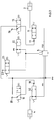
- Fig. 1 1 designates an exemplary embodiment of a pressure control device, which comprises a valve unit 2 and an electronic unit mechanically and electrically directly connected to it as a control unit, which is not shown here for reasons of scale.
- the pressure control device 1 is preferably integrated in a compressed air brake system of a commercial vehicle.
- the pressure control device 1 is designed for wheel-specific, at least brake slip-dependent control of brake pressures in brake cylinders 3, 4 of wheels of a driven axle, for example.
- it comprises a single relay valve 5, with one of one Supply pressure p11 supplied supply connection 6, a ventilation connection 7 connected to a pressure sink, a control connection 8 and with two working connections 9, 10.
- a working port 9 is assigned to a brake cylinder 3 of a wheel of a vehicle side of the axle and the other working port 10 of the single relay valve 5 is assigned to the brake cylinder 4 of the wheel of the other vehicle side of the axle, in order to apply a brake pressure p21 in the brake cylinder 4 or a brake pressure p22 in the To be able to control brake cylinder 3.
- each working connection 9, 10 of the relay valve 5 is connected to a 2/2-way valve 11, 12, which is preferably indirectly controlled by the control unit and is assigned to one vehicle side.
- the 2/2-way valves 11, 12 either establish a connection between the relevant working connection 9, 10 of the relay valve 5 and the associated brake cylinder 3, 4, or block this connection, depending on a preferably indirect control by the control device.
- the control port 8 of the relay valve can be connected to a brake control pressure p4, which is formed as a function of the driver's brake request, or to a pressure sink 14, for example by means of a valve device formed by, for example, a 3/2-way solenoid valve 13 and controlled by the control device.
- the 3/2-way solenoid valve 13 is preferably spring-loaded and thus biased without current into the switching position in which it connects the control port 8 of the relay valve 5 with the brake control pressure p4 formed depending on the driver's brake request.
- the control connection 8 of the relay valve 5 is connected to the pressure sink 14.
- the brake control pressure p4 formed depending on the driver's brake request is generated, for example, by a driver-operated foot brake module, not shown here.
- the 2/2-way valves 11, 12 are particularly preferably pneumatically controllable diaphragm valves, which are preferably pneumatically piloted by a 3/2-way pilot solenoid valve 15, 16 which is electrically controlled by the control unit and assigned to the same vehicle side.
- the 3/2-way pilot solenoid valves 15, 16 are preferably designed such that they control or control the supply pressure p11 of the pressure reservoir to a control connection 17, 18 of the assigned 2/2-way valve 11, 12 depending on a control by the control device on the other hand, connect this control connection 17, 18 to a pressure sink 19, 20.
- the 3/2-way pilot solenoid valves 15, 16 are preferably spring-loaded and thus biased without current into the switching position in which they connect the control connection 17, 18 of the associated 2/2-way valve 11, 12 to the pressure sink. In contrast, when current is supplied, the control connections 17, 18 of the 2/2-way valves 11, 12 are connected to the pressure sink 19, 20.
- the control device is designed so that by controlling the 3/2-way solenoid valve 13 and the two 3/2-way pilot solenoid valves 15, 16 for indirect control of the 2/2-way valves 11, 12, a wheel-specific brake slip control in the frame the typical ABS functions of pressure increase, pressure maintenance and pressure reduction in order to achieve an optimal target brake slip.
- the control unit receives information in a known manner about the wheel speeds of the wheels of the axle via wheel speed sensors, not shown here.
- the central 3/2-way solenoid valve 13 for piloting the relay valve 5 and the two 3/2-way pilot solenoid valves 15, 16 are in the in Fig. 1 shown spring-operated currentless basic position, so that the 3/2-way solenoid valve 13 connects the control port 8 of the relay valve 5 with the brake control pressure p4 formed depending on the driver's brake request. Consequently, the relay valve 5 modulates a brake pressure p21 or p22 from this brake control pressure p4 at its two working ports 9, 10.
- the pneumatic control ports are 17, 18 of the two 2/2-way valves 11, 12 each connected to the pressure sinks 19, 20, so that they are in the in Fig. 1 shown passage position to control the brake pressure p21 or p22 applied to the working connections 9, 10 of the relay valve 5 into the brake cylinders 3, 4.
- the brake pressures p21 and p22 for one side of the vehicle and the other side of the vehicle are essentially the same.
- the 3/2-way solenoid valve 13 is first energized and thereby switched to its venting position, in which the control connection 8 of the relay valve 5 is connected to the pressure sink 14.
- both working connections 9, 10 of the relay valve 5 are connected to its pressure sink 7.
- the 3/2-way pilot solenoid valve 15 is energized by the control unit on the vehicle side on which no wheel locking occurs by energizing into the position in which the control port 17 of the 2/2-way valve in question is acted upon by the supply pressure p11 .
- the 2/2-way valve 11 switches into its blocking position and thereby maintains the brake pressure p22 in the brake cylinder 3 of the non-blocking wheel (maintaining pressure).
- the 3/2-way pilot solenoid valve 16 is not switched by the control unit, but remains in its de-energized basic position, in which the control connection 18 of the relevant 2/2-way valve 12 remains switched to the pressure sink 20.
- the 2/2-way valve 12 remains in its Fig. 1 Pass position shown, whereby the brake pressure p21 can decrease in the brake cylinder 4 of the blocking wheel via the pressure sink 7 of the relay valve 5 (pressure sinks).
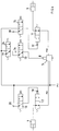
- the valve device consists of two 2/2-way solenoid valves 21, 22, the one 2/2-way solenoid valve 21 serving as the outlet valve controlling the control port 8 of the relay valve 5 either with a pressure sink 23 connects or blocks this connection as shown.
- the further 2/2-way solenoid valve 22 either connects the control connection 8 of the relay valve 5 to the brake control pressure p4, which is formed as a function of the driver's brake request, or blocks this connection.
- Both 2/2-way solenoid valves 21, 22 are spring-loaded in their Fig. 2 shown basic position switched, in which the one 2/2-way solenoid valve 21 is in the blocking position and the other 2/2-way solenoid valve 22 is switched in the open position.
- the following functions of the in Fig. 2 shown pressure control device 1 During normal service braking, one 2/2-way solenoid valve 21 is in the de-energized blocking position, and the other 2/2-way solenoid valve 22 is in the open position. Still are also the two 3/2-way pilot solenoid valves 15, 16 in the in Fig. 2 shown spring-operated currentless basic position, so that the other 2/2-way solenoid valve 22 connects the control port 8 of the relay valve 5 with the brake control pressure p4 formed depending on the driver's brake request, such as Fig. 2 shows. As described above, the relay valve 5 modulates a brake pressure p21 or p22 from this brake control pressure p4 at its two working ports 9, 10.
- the two 3/2-way pilot solenoid valves 15, 16 are also in their de-energized basic position, they are Pneumatic control connections 17, 18 of the two 2/2-way valves 11, 12 each connected to the pressure sinks 19, 20, so that they are in the in Fig. 2 shown passage position to control the brake pressure p21 or p22 applied to the working connections 9, 10 of the relay valve 5 into the brake cylinders 3, 4.
- the brake pressures p21 and p22 for one side of the vehicle and the other side of the vehicle are essentially the same.
- the 2/2-way solenoid valve is energized as an outlet valve 21 and thereby switched to its open position, in which the control connection 8 of the relay valve 5 is connected to the pressure sink 23.
- the further 2/2-way solenoid valve 22 is also energized and thereby switched into its blocking position, whereby the control connection 8 of the relay valve 5 is decoupled from the brake control pressure p4.
- both working connections 9, 10 of the relay valve 5 are connected to its pressure sink 7.
- the two 3/2-way pilot solenoid valves 15, 16 are switched as described in the previous exemplary embodiment, so that the 2/2-way valve 11 of the non-blocking vehicle side is switched into its blocking position, as a result of which the brake pressure p22 in the brake cylinder 3 of the non-blocking wheel is held. (Keeping pressure).
- the 3/2-way pilot solenoid valve 16 is not switched by the control unit, but remains in its de-energized basic position, in which the control connection 18 of the relevant 2/2-way valve 12 remains switched to the pressure sink 20.
- the 2/2-way valve 12 remains in its Fig. 2 Pass position shown, whereby the brake pressure p21 can decrease in the brake cylinder 4 of the blocking wheel via the pressure sink 7 of the relay valve 5 (pressure sinks).
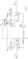
- Fig. 3 is different from the embodiments Fig. 1 and Fig. 2 not a supply pressure p11 of a pressure reservoir, but the brake control pressure p4, which is formed as a function of the driver's brake request, is switched via the two 3/2-way pilot solenoid valves 15, 16 to the control connections 17, 18 of the 2/2-way valves 11, 12. If the ABS is then in a pressure-holding phase during driver-initiated braking and the driver releases the brake pedal during this pressure-holding phase, the control pressure p4 formed depending on the driver's brake request drops so that the associated 2/2-way valve 11 or 12, which is closed during the pressure-holding phase, can open, to reduce brake pressure p21 or p22 (pressure reduction).
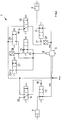
- ABS-compatible basic layout according to 1 to 3 is used to implement a traction control system (ASR) using only one solenoid valve 24 electrically controlled by the control device according to the embodiment of FIG Fig. 4 added.
- This solenoid valve 24 then interacts with the valve device 13 in such a way that the control connection 8 of the single relay valve 5 is connected to the control pressure p4, the supply pressure p11 of the pressure reservoir or the pressure sink 14, depending on the drive slip of the wheels of the axle.
- Solenoid valve a 3/2-way solenoid valve 24, the valve device is analogous to Fig. 1 also formed by a 3/2-way solenoid valve 13.
- control unit is designed such that, in addition to the ABS functions, at least the additional 3/2-way solenoid valve is also used to implement a wheel-specific traction control system (ASR).
- ASR wheel-specific traction control system
- This additional 3/2-way solenoid valve 24 is seen on the control side of the relay valve 5 upstream of the 3/2-way solenoid valve 13 forming the valve device. In its spring-loaded, de-energized basic position, it switches the control pressure p4, which is formed as a function of the driver's brake request, and in its energized switching position, the supply pressure p11 to the 3/2-way solenoid valve 13.
- the additional ASR valve 24 switches the control pressure p4 formed on the basis of the driver brake request to the 3/2-way solenoid valve 13, as a result of which the control connection 8 of the relay valve 5 as in the exemplary embodiment of Fig. 1 described ventilated or vented, depending on whether the control pressure p4 formed depending on the driver's brake request represents a brake release control pressure or a brake application control pressure.
- a brake release control pressure p4 ie when the foot brake valve is not actuated, the relay valve 5 only controls a low brake release pressure p21 or p22 to its working connections 9, 10, so that both wheel brake cylinders 3, 4 are released.
- the additional ASR valve 24 switches the supply pressure p11 to the 3/2-way solenoid valve 13 which is switched to the open position, as a result of which the control port 8 of the relay valve 5 is ventilated by a brake application control pressure and therefore a brake application pressure to it Working ports 9, 10 modulated.
- the switching positions of the 3/2-way pilot solenoid valves 15, 16 and the two 2/2-way valves 11, 12 are then as in Fig. 4 shown, so that the wheel brake cylinders 3, 4 of the axle are temporarily clamped during the presence of impermissible wheel slip in the sense of a wheel slip control.
- Fig. 5 is like the embodiment of Fig. 3 not the supply pressure p11 of the pressure reservoir, but the brake control pressure p4, which is formed as a function of the driver's brake request, is switched via the two 3/2-way pilot solenoid valves 15, 16 to the control connections 17, 18 of the two 2/2-way valves 11, 12. If the ASR is then in a pressure holding phase and the driver depresses the brake pedal during this pressure holding phase, the control pressure p4 formed depending on the driver's brake request increases, so that the associated 2/2-way valve 11 or 12, which is closed during the pressure holding phase, can open to brake pressure p21 or . build up p22 (pressure risers).
- the one 2/2-way solenoid valve 21 is preferably an outlet valve, which either connects the control port 8 of the relay valve 5 to its pressure sink 23 or blocks this connection.
- the other 2/2-way solenoid valve 22 is in particular a valve which can also be used as a backup valve of an EBS and which either connects the control port 8 of the relay valve 5 to the control pressure p4 formed depending on the driver's brake request or blocks this connection.
- the only additional solenoid valve provided for realizing the traction control of the axle is according to the embodiment of the invention from Fig.
- an inlet valve 26 designed as a 2/2-way solenoid valve. According to Fig. 6 is then formed by the inlet valve 26, the outlet valve 21 and the backup valve 22 not only a brake slip control (ABS) and a traction control system (ASR) but also an electronic brake system (EBS) with priority electro-pneumatic brake circuit and subordinate pneumatic brake circuit, if additionally, for example, a working connection 9, 10 of the single relay valve 5 is in pressure-conducting connection with a pressure sensor 27.
- ABS brake slip control
- ASR traction control system
- EBS electronic brake system
- control unit is designed such that, in addition to carrying out the ABS and ASR functions, it also adjusts the actual brake pressure measured by the pressure sensor 27 to a target brake pressure, which is formed as a function of the driver's brake, in the sense of a brake pressure control, by controlling the inlet valve 26 and the outlet valve 21 .
- the outlet valve 21 remains in its spring-loaded blocking position, while the inlet valve 26 is switched to the through position in order to vent the control port 8 of the relay valve 5 with supply pressure.
- This ensures brake application pressure p21 or p22 at the two working connections 9, 10 of the relay valve 5, which are controlled via the two connected 2/2-way valves 11, 12 to the wheel brake cylinders 3, 4.
- the backup valve 22 remains in its energized blocking position, so that the control pressure p4 generated at it depending on the driver's brake request cannot be switched through to the control port 8 of the relay valve 5.
- the solenoid valves 15, 16, 21, 22, 26 can no longer be energized.
- the inlet valve 26 switches to its de-energized and spring-loaded blocking position back so that no supply pressure reaches control port 8 of relay valve 5.
- the outlet valve 21 also remains in the blocking position.
- the control connection 8 of the relay valve 5 is then acted upon by the backup valve 22, which is switched to the open position in the current-free, spring-loaded manner, with the control pressure p4 generated by the foot brake valve as a function of the driver brake request, in order to apply the wheel brake cylinders 3, 4.
- ABS or ASR functions then run as in the previously described embodiments, i.e.
- the control connection 8 of the relay valve 5 is connected functionally via the inlet valve 26 to the supply pressure p11, via the backup valve 22 to the control pressure p4 formed depending on the driver's brake request or via the outlet valve 21 to the pressure sink 23 of the outlet valve 21.
- a further pressure sensor 28 is provided for measuring the brake control pressure p4 which is formed as a function of the driver's brake request. If in each case one pressure control device 1 according to Fig. 6 A vehicle dynamics control (ESP) can be implemented for each axle, for example for a front axle and for a rear axle.
- ESP vehicle dynamics control
- the control unit is designed such that when braking is initiated by the vehicle dynamics control (ESP), it controls the exhaust valve 21, the backup valve 22 and the intake valve 26 such that the control port 8 of the relay valve 5 depends on the yaw rate of the vehicle through the supply pressure p11 of the pressure reservoir is applied.
- ESP vehicle dynamics control
- the outlet valve 21 and the backup valve 22 are switched to their blocking position, while the inlet valve 26 is switched to the open position in order to vent the control connection 8 of the relay valve 5.
- the 3/2-way pilot solenoid valves 15, 16 are controlled by the control device such that, for example, the 2/2-way valve 11 assigned to the one brake cylinder 3 on the one side of the vehicle is switched to the open position in order to vent this brake cylinder and that other 2/2-way valve 12 assigned to the other brake cylinder 4 on the other side of the vehicle is switched to the blocking position in order to shut off this brake cylinder 4 from the build-up of pressure.
- the 2/2-way valve 11 is switched into the blocking position and the 2/2-way valve 12 in the open position by appropriate activation of the 3/2-way pilot solenoid valves 15, 16 got to.
Landscapes
- Engineering & Computer Science (AREA)
- Transportation (AREA)
- Mechanical Engineering (AREA)
- Physics & Mathematics (AREA)
- Fluid Mechanics (AREA)
- Electromagnetism (AREA)
- Regulating Braking Force (AREA)
Claims (10)
- Dispositif (1) de commande de la pression pour un système de frein à fluide sous pression d'un véhicule afin de commander d'une manière individuelle à une roue et au moins en fonction du glissement du freinage des pressions de frein dans des cylindres (3, 4) de frein de roues d'un essieu, dans lequela) il contient une vanne (5) relais unique ayant un raccord (6) de réserve alimenté en une pression (p11) de réserve, un raccord (7) de purge communiquant avec un puits de pression, un raccord (8) de commande et au moins deux raccords (9, 10) de travail, l'un (9) des raccords de travail étant associé à au moins un cylindre (3) de frein d'une roue d'un côté du véhicule de l'essieu et l'autre raccord (10) de travail de la vanne (5) relais étant associé au moins à un cylindre (4) de frein d'une roue de l'autre côté du véhicule de l'essieu,b) chaque raccord (9, 10) de travail de la vanne (5) relais communique avec une vanne (11, 12) à 2/2 voies commandée directement ou indirectement par un appareil de commande et associé, respectivement, à un côté du véhicule, laquelle, en fonction de la commande par l'appareil de commande, ménage une communication entre le raccord (9, 10) de travail concerné de la vanne relais et le cylindre (3, 4) de frein associé ou barre cette communication, dans lequelc) pour la réalisation d'une régulation (ASR) de glissement en traction, un dispositif (21, 22) de vanne coopère avec une électrovanne (26) unique commandée électriquement par l'appareil de commande de manière à ce que le raccord (8) de commande de la vanne (5) relais soit, en fonction du glissement en traction des roues de l'essieu, par la pression (p4) de commande formée en fonction du souhait de freinage du conducteur, relié à une pression (p11) de réserve d'un réservoir de pression ou à un puits (14, 23) de pression, caractérisé en ce qued) le raccord (8) de commande de la vanne (5) relais peut, au moyen du dispositif de vanne formé par deux électrovannes (21, 22) à 2/2 voies et commandé au moyen de l'appareil de commande, être relié soit à une pression (p4) de commande de frein formée en fonction du souhait de freinage du conducteur, soit à un puits (23) de pression, dans lequele) la une électrovanne (21) à 2/2 voies des deux électrovannes (21, 22) à 2/2 voies formant le dispositif de vanne est une vanne de sortie qui relie le raccord (8) de commande de la vanne (5) relais soit à un puits (23) de pression, soit barre cette liaison, et en ce quef) l'autre électrovanne (22) à 2/2 voies des deux électrovannes (21, 22) à 2/2 voies formant le dispositif de vanne est une vanne de Backup d'un système (EBS) électronique de frein ayant un circuit électropneumatique de frein de premier rang et un circuit pneumatique de frein de deuxième rang qui soit relie le raccord (8) de commande de la vanne (5) relais à la pression (p4) de commande formée en fonction du souhait de freinage du conducteur, soit barre cette liaison, et en ce queg) l'électrovanne (26) supplémentaire unique prévue pour réaliser la régulation du glissement en traction est une vanne d'entrée constituée en électrovanne à 2/2 voies ayant une position de passage et une position de barrage, la vanne d'entrée alimentant dans la position de passage le raccord (8) de commande de la vanne (5) relais en la pression (p11) de réserve, dans lequelh) le dispositif de vanne de commande de la pression comporte, pour la constitution du système (EBS) électronique de frein ayant un circuit électropneumatique de frein de premier rang et un circuit pneumatique de frein de deuxième rang, au moins un capteur (27) de pression en liaison conduisant la pression avec au moins un raccord (9, 10) de travail de la vanne (5) relais, dans lequeli) l'appareil de commande est constitué de manière à adapter à une valeur de frein de consigne formée en fonction du souhait de freinage du conducteur par commande de la vanne (26) d'entrée et de la vanne (21) de sortie la pression de frein réelle mesurée par le au moins un capteur (27) de pression.
- Dispositif de commande de la pression suivant la revendication 1, caractérisé en ce que chaque vanne (11, 12) à 2/2 voies associée à un côté du véhicule est pilotée pneumatiquement par, respectivement, une électrovanne (15, 16) de pilotage à 3/2 voies commandée électriquement par l'appareil de commande et associée au même côté du véhicule.
- Dispositif de commande de la pression suivant la revendication 2, caractérisé en ce que les vannes (11, 12) à 2/2 voies sont des vannes à membrane ou des vannes Booster.
- Dispositif de commande de la pression suivant la revendication 2 ou 3, caractérisé en ce que les électrovannes (15, 16) de pilotage à 3/2 voies sont constituées de manière, en fonction d'une commande par l'appareil de commande, à appliquer, d'une part, la pression (p11) de réserve du réservoir de pression ou la pression (p4) de commande formée en fonction du souhait de freinage du conducteur à un raccord (17, 18) de commande de la vanne (11, 12) à 2/2 voies associé ou, d'autre part, à relier ce raccord (17, 18) de commande à un puits (19, 20) de pression.
- Dispositif de commande de la pression suivant l'une des revendications précédentes, caractérisé en ce que l'appareil de commande est constitué de manière à réaliser, par la commande au moins du dispositif (21, 22) de vanne et des vannes (11, 12) à 2/2 voies associées, respectivement, à un côté du véhicule, une régulation du glissement en freinage individuelle à une roue.
- Dispositif de commande de la pression suivant l'une des revendications précédentes, caractérisé en ce que l'appareil de commande est constitué de manière à réaliser, par la commande au moins de l'électrovanne (26) < supplémentaire unique, une régulation du glissement en traction (ASR) individuelle à une roue.
- Dispositif de commande de la pression suivant l'une des revendications précédentes, caractérisé en ce que, pour constituer une régulation dynamique en marche (ESP), il est prévu un autre capteur (28) de pression pour mesurer la pression (p4) de commande formée en fonction du souhait de freinage du conducteur.
- Dispositif de commande de la pression suivant l'une des revendications précédentes, caractérisé en ce que l'appareil de commande est constitué de manière à commander, lors d'un freinage amorcé par la régulation (ESP) dynamique en marche, au moins le dispositif (21, 22) de soupape ainsi que l'électrovanne (26) supplémentaire unique, de manière à ce quea) le raccord (8) de commande de la vanne (5) relais soit soumis, en fonction du taux d'embardée du véhicule, à la pression (p11) de réserve du réservoir de pression,b) la vanne (11) à 2/2 voies, associée à un cylindre (3) de frein d'un côté du véhicule, soit mise dans une position de passage, etc) en ce que la vanne (12) à 2/2 voies, associée à l'autre cylindre (4) de frein de l'autre côté du véhicule, soit mise en une position de barrage.
- Dispositif (EBS) électronique de frein régulé dynamiquement en marche d'un véhicule comprenant une régulation (ESP) dynamique en marche ayant pour chaque essieu au moins un système de commande de pression suivant la revendication 7 ou 8.
- Dispositif de frein d'un véhicule comprenant au moins un système de commande de pression suivant l'une des revendications 1 à 8.
Applications Claiming Priority (2)
| Application Number | Priority Date | Filing Date | Title |
|---|---|---|---|
| DE102010010606.2A DE102010010606B4 (de) | 2010-03-08 | 2010-03-08 | Modular aufgebaute Drucksteuervorrichtung einer Druckmittel-Bremsanlage eines Fahrzeugs |
| PCT/EP2011/053141 WO2011110459A1 (fr) | 2010-03-08 | 2011-03-08 | Dispositif de régulation de pression de conception modulaire d'un système de freinage à fluide sous pression d'un véhicule |
Publications (2)
| Publication Number | Publication Date |
|---|---|
| EP2544932A1 EP2544932A1 (fr) | 2013-01-16 |
| EP2544932B1 true EP2544932B1 (fr) | 2020-07-29 |
Family
ID=43790456
Family Applications (1)
| Application Number | Title | Priority Date | Filing Date |
|---|---|---|---|
| EP11714497.2A Active EP2544932B1 (fr) | 2010-03-08 | 2011-03-08 | Dispositif de régulation de pression de conception modulaire d'un système de freinage à fluide sous pression d'un véhicule |
Country Status (5)
| Country | Link |
|---|---|
| US (1) | US8918262B2 (fr) |
| EP (1) | EP2544932B1 (fr) |
| CN (2) | CN201777230U (fr) |
| DE (1) | DE102010010606B4 (fr) |
| WO (1) | WO2011110459A1 (fr) |
Families Citing this family (19)
| Publication number | Priority date | Publication date | Assignee | Title |
|---|---|---|---|---|
| DE102010010606B4 (de) * | 2010-03-08 | 2015-02-19 | Knorr-Bremse Systeme für Nutzfahrzeuge GmbH | Modular aufgebaute Drucksteuervorrichtung einer Druckmittel-Bremsanlage eines Fahrzeugs |
| DE102011080169A1 (de) * | 2011-08-01 | 2013-02-07 | Robert Bosch Gmbh | Kommunikationsanbindung für Sensorik in Fahrzeug-Regelsystemen |
| EP2821303B1 (fr) * | 2013-07-05 | 2016-09-14 | KNORR-BREMSE Systeme für Nutzfahrzeuge GmbH | Frein de stationnement électropneumatique |
| DE102013016877B3 (de) | 2013-10-11 | 2014-10-09 | Knorr-Bremse Systeme für Nutzfahrzeuge GmbH | Verfahren zum Steuern einer Drucksteuervorrichtung einer Druckmittel-Bremsanlage eines Fahrzeugs |
| DE102014006614A1 (de) * | 2014-05-08 | 2015-11-26 | Wabco Gmbh | Pneumatische Bremseinrichtung für Kraftfahrzeuge und Verfahren zum Betrieb einer pneumatischen Bremsanlage |
| CN104494589B (zh) * | 2014-11-28 | 2016-12-07 | 中国北车集团大连机车车辆有限公司 | 铁路机车制动系统备用控制装置 |
| US10150457B2 (en) | 2016-04-28 | 2018-12-11 | Bendix Commercial Vehicle Systems Llc | Valve module for an air braking system of a heavy vehicle |
| DE102017214111A1 (de) * | 2017-08-11 | 2019-02-14 | Knorr-Bremse Systeme für Schienenfahrzeuge GmbH | Elektropneumatisch geregelte Ansteuerung eines Stromabnehmers |
| DE102017009954A1 (de) * | 2017-10-26 | 2019-05-02 | Wabco Gmbh | Achsventilmodul und Relaisventilmodul einer Druckluftbremsanlage |
| DE102018108090A1 (de) | 2018-04-05 | 2019-10-10 | Wabco Gmbh | Elektro-pneumatischer Achsmodulator mit direkt gesteuerten Ventilen |
| DE102018215295A1 (de) * | 2018-09-07 | 2020-03-12 | Knorr-Bremse Systeme für Schienenfahrzeuge GmbH | Verteilte Reglerstruktur zur Erzielung optimierter Reglereigenschaften sowie erhöhter Ventillebensdauer |
| CN109532795B (zh) * | 2018-10-15 | 2023-12-26 | 厦门金龙汽车新能源科技有限公司 | 电动车辆的驻车制动系统、电动车辆及控制方法 |
| DE102018127822A1 (de) | 2018-11-07 | 2020-05-07 | Knorr-Bremse Systeme für Nutzfahrzeuge GmbH | Ventilanordnung und ein Verfahren zur Drucksteuerung |
| CN109733371B (zh) * | 2019-03-01 | 2023-12-26 | 浙江力邦合信智能制动系统股份有限公司 | 用于商用车辆的高气流电动气动阀 |
| CN111098969A (zh) * | 2020-01-16 | 2020-05-05 | 宁波赛福汽车制动有限公司 | 一种新型的两轮车制动防抱死系统 |
| CN113529843B (zh) * | 2020-04-22 | 2023-07-04 | 山河智能装备股份有限公司 | 压力耦合液压混合动力驱动回路及其控制方法、挖掘机 |
| CN113548027B (zh) * | 2021-09-18 | 2022-03-04 | 天津所托瑞安汽车科技有限公司 | 一种转向桥的制动压力控制模块及控制方法 |
| DE102022100611A1 (de) * | 2022-01-12 | 2023-07-13 | Knorr-Bremse Systeme für Schienenfahrzeuge GmbH | Druckluftbremsanlage für ein Fahrzeug und Verfahren zum Betreiben der Druckluftbremsanlage |
| CN116691629A (zh) * | 2022-07-29 | 2023-09-05 | 宇通客车股份有限公司 | 一种带有辅助行车制动的制动系统 |
Citations (2)
| Publication number | Priority date | Publication date | Assignee | Title |
|---|---|---|---|---|
| DE2810219A1 (de) * | 1978-03-09 | 1979-09-20 | Bosch Gmbh Robert | Drucksteuerventil-aggregat ii |
| FR2419199A1 (fr) * | 1978-03-09 | 1979-10-05 | Bosch Gmbh Robert | Appareil de commande de pression pour dispositif antiblocage des roues d'un vehicule automobile |
Family Cites Families (12)
| Publication number | Priority date | Publication date | Assignee | Title |
|---|---|---|---|---|
| DE3700716A1 (de) | 1987-01-13 | 1988-07-21 | Wabco Westinghouse Fahrzeug | Fahrzeug mit antiblockiersystem und antriebsschlupfregelung |
| US5342119A (en) * | 1992-12-28 | 1994-08-30 | Eaton Corporation | Traction control system valve |
| DE4425789C2 (de) * | 1994-07-21 | 1996-06-13 | Grau Gmbh | Bremsanlage für pneumatisch gebremste Anhängerfahrzeuge |
| GB9509740D0 (en) * | 1995-05-13 | 1995-07-05 | Grau Ltd | Vehicle braking system |
| DE10038046B4 (de) * | 2000-08-02 | 2005-11-03 | Knorr-Bremse Systeme für Nutzfahrzeuge GmbH | Stabilisierungseinrichtung für Kraftfahrzeuge mit druckluftbetriebenen Bremseinrichtungen |
| DE10236922A1 (de) | 2002-08-12 | 2004-03-04 | Knorr-Bremse Systeme für Nutzfahrzeuge GmbH | Druckregelmodul für eine Druckluft-Bremsanlage eines Fahrzeugs |
| DE102004024462A1 (de) * | 2004-05-14 | 2005-12-08 | Knorr-Bremse Systeme für Schienenfahrzeuge GmbH | Elektropneumatische Bremseinrichtung eines Schienenfahrzeugs mit durchgängigem Regelbereich |
| DE102005060225A1 (de) * | 2005-12-16 | 2007-06-21 | Wabco Gmbh | Elektropneumatische Bremssteuerungseinrichtung |
| DE102006041009A1 (de) * | 2006-08-31 | 2008-03-06 | Wabco Gmbh | Bremsanlage für ein Fahrzeug |
| DE102008009882A1 (de) * | 2008-02-19 | 2009-08-20 | Wabco Gmbh | Feststellbremse für ein Fahrzeug und Verfahren zum Betrieb der Feststellbremse |
| DE102008035335A1 (de) * | 2008-07-29 | 2010-02-04 | Man Nutzfahrzeuge Aktiengesellschaft | Druckmittelbetätigte Bremsvorrichtung für Kraftfahrzeuge |
| DE102010010606B4 (de) * | 2010-03-08 | 2015-02-19 | Knorr-Bremse Systeme für Nutzfahrzeuge GmbH | Modular aufgebaute Drucksteuervorrichtung einer Druckmittel-Bremsanlage eines Fahrzeugs |
-
2010
- 2010-03-08 DE DE102010010606.2A patent/DE102010010606B4/de active Active
- 2010-08-02 CN CN2010202811126U patent/CN201777230U/zh not_active Expired - Lifetime
-
2011
- 2011-03-08 CN CN201180013282.3A patent/CN102791547B/zh active Active
- 2011-03-08 US US13/583,497 patent/US8918262B2/en active Active
- 2011-03-08 EP EP11714497.2A patent/EP2544932B1/fr active Active
- 2011-03-08 WO PCT/EP2011/053141 patent/WO2011110459A1/fr not_active Ceased
Patent Citations (2)
| Publication number | Priority date | Publication date | Assignee | Title |
|---|---|---|---|---|
| DE2810219A1 (de) * | 1978-03-09 | 1979-09-20 | Bosch Gmbh Robert | Drucksteuerventil-aggregat ii |
| FR2419199A1 (fr) * | 1978-03-09 | 1979-10-05 | Bosch Gmbh Robert | Appareil de commande de pression pour dispositif antiblocage des roues d'un vehicule automobile |
Also Published As
| Publication number | Publication date |
|---|---|
| WO2011110459A1 (fr) | 2011-09-15 |
| US8918262B2 (en) | 2014-12-23 |
| US20130073165A1 (en) | 2013-03-21 |
| EP2544932A1 (fr) | 2013-01-16 |
| CN201777230U (zh) | 2011-03-30 |
| DE102010010606A1 (de) | 2011-09-08 |
| DE102010010606B4 (de) | 2015-02-19 |
| CN102791547A (zh) | 2012-11-21 |
| CN102791547B (zh) | 2016-01-20 |
Similar Documents
| Publication | Publication Date | Title |
|---|---|---|
| DE102010010606B4 (de) | Modular aufgebaute Drucksteuervorrichtung einer Druckmittel-Bremsanlage eines Fahrzeugs | |
| EP3183148B1 (fr) | Procédé pour commander un dispositif de freinage de service d'un véhicule et dispositif soupape de freinage de service pour un tel dispositif de freinage de service | |
| DE102014013756B3 (de) | Elektrische Ausrüstung eines Fahrzeugs mit einer wenigstens teilweise elektrischen Brems- und Lenkeinrichtung mit hoher Verfügbarkeit | |
| EP3344503B1 (fr) | Système de freinage pneumatique commandable électroniquement dans un véhicule utilitaire ainsi que procédé de commande d'un système de freinage pneumatique | |
| EP2632780B1 (fr) | Dispositif de freinage d'un véhicule, actionné par fluide sous pression, comportant des procédures de commande d'une fonction d'aide au démarrage en côte ou de suppression du rampement, implémentées dans une unité de commande | |
| EP3717320B1 (fr) | Systeme de freinage pour vehicules automobiles et procede de fonctionnement d'un systeme de freinage | |
| EP3700788B1 (fr) | Module de soupapes d'essieu et module de soupape relais pour un système de freins pneumatique | |
| EP3642089A1 (fr) | Équipement électrique pour un véhicule ou une combinaison de véhicules comprenant un véhicule tracteur et au moins un véhicule tracté | |
| EP2822822A2 (fr) | Procédé de détermination d'une courbe caractéristique pression-volume d'un frein sur roue | |
| DE102014118943A1 (de) | Verfahren zur Steuerung einer elektropneumatischen Parkbremseinrichtung mit dynamischer Blockierverhinderung | |
| DE102017102021A1 (de) | Elektrische Ausrüstung eines Fahrzeugs mit einer wenigstens teilweise elektrischen Brems- und Lenkeinrichtung | |
| EP2678201B1 (fr) | Système de freinage à régulation anti-patinage pour un véhicule automobile approchant un point d'arrêt | |
| WO2009103330A1 (fr) | Frein de stationnement pour véhicule, et procédé permettant de faire fonctionner ce frein de stationnement | |
| EP2419309B1 (fr) | Procédé de contrôle d'un véhicule dont seul l'essieu arrière est freiné et contrôleutr de glissement de freinage | |
| EP2256011B1 (fr) | Système de freinage pour véhicule et procédé pour faire fonctionner ce système de freinage | |
| EP3055175B1 (fr) | Procédé de commande d'un dispositif de commande de pression d'un système de freinage à fluide sous pression d'un véhicule automobile | |
| DE102009016982C5 (de) | Verfahren zum Betreiben einer Bremseinrichtung eines Haltestellen anfahrenden Kraftfahrzeugs | |
| DE102010007407B4 (de) | Drucksteuerventilanordnung | |
| DE102010020267B4 (de) | Druckmittelbestätigte Bremseinrichtung mit Niederdruck- und Hochdruckbereich | |
| DE102005061543B4 (de) | Hydraulische Zweikreis-Fahrzeugbremsanlage | |
| DE10304145A1 (de) | Elektrohydraulische Fahrzeugbremsanlage | |
| DE102019002452A1 (de) | Bremssystem und Verfahren zum Betreiben eines Bremssystems für ein Fahrzeug | |
| DE102024114057A1 (de) | Elektronisch steuerbares pneumatisches Bremssystem mit Anti-Compound-Funktion |
Legal Events
| Date | Code | Title | Description |
|---|---|---|---|
| PUAI | Public reference made under article 153(3) epc to a published international application that has entered the european phase |
Free format text: ORIGINAL CODE: 0009012 |
|
| 17P | Request for examination filed |
Effective date: 20121008 |
|
| AK | Designated contracting states |
Kind code of ref document: A1 Designated state(s): AL AT BE BG CH CY CZ DE DK EE ES FI FR GB GR HR HU IE IS IT LI LT LU LV MC MK MT NL NO PL PT RO RS SE SI SK SM TR |
|
| DAX | Request for extension of the european patent (deleted) | ||
| 17Q | First examination report despatched |
Effective date: 20160425 |
|
| GRAP | Despatch of communication of intention to grant a patent |
Free format text: ORIGINAL CODE: EPIDOSNIGR1 |
|
| STAA | Information on the status of an ep patent application or granted ep patent |
Free format text: STATUS: GRANT OF PATENT IS INTENDED |
|
| INTG | Intention to grant announced |
Effective date: 20200225 |
|
| GRAS | Grant fee paid |
Free format text: ORIGINAL CODE: EPIDOSNIGR3 |
|
| GRAA | (expected) grant |
Free format text: ORIGINAL CODE: 0009210 |
|
| STAA | Information on the status of an ep patent application or granted ep patent |
Free format text: STATUS: THE PATENT HAS BEEN GRANTED |
|
| AK | Designated contracting states |
Kind code of ref document: B1 Designated state(s): AL AT BE BG CH CY CZ DE DK EE ES FI FR GB GR HR HU IE IS IT LI LT LU LV MC MK MT NL NO PL PT RO RS SE SI SK SM TR |
|
| REG | Reference to a national code |
Ref country code: GB Ref legal event code: FG4D Free format text: NOT ENGLISH |
|
| REG | Reference to a national code |
Ref country code: CH Ref legal event code: EP |
|
| REG | Reference to a national code |
Ref country code: DE Ref legal event code: R096 Ref document number: 502011016829 Country of ref document: DE |
|
| REG | Reference to a national code |
Ref country code: AT Ref legal event code: REF Ref document number: 1295419 Country of ref document: AT Kind code of ref document: T Effective date: 20200815 |
|
| REG | Reference to a national code |
Ref country code: IE Ref legal event code: FG4D Free format text: LANGUAGE OF EP DOCUMENT: GERMAN |
|
| REG | Reference to a national code |
Ref country code: NL Ref legal event code: FP |
|
| REG | Reference to a national code |
Ref country code: SE Ref legal event code: TRGR |
|
| REG | Reference to a national code |
Ref country code: LT Ref legal event code: MG4D |
|
| PG25 | Lapsed in a contracting state [announced via postgrant information from national office to epo] |
Ref country code: BG Free format text: LAPSE BECAUSE OF FAILURE TO SUBMIT A TRANSLATION OF THE DESCRIPTION OR TO PAY THE FEE WITHIN THE PRESCRIBED TIME-LIMIT Effective date: 20201029 Ref country code: NO Free format text: LAPSE BECAUSE OF FAILURE TO SUBMIT A TRANSLATION OF THE DESCRIPTION OR TO PAY THE FEE WITHIN THE PRESCRIBED TIME-LIMIT Effective date: 20201029 Ref country code: ES Free format text: LAPSE BECAUSE OF FAILURE TO SUBMIT A TRANSLATION OF THE DESCRIPTION OR TO PAY THE FEE WITHIN THE PRESCRIBED TIME-LIMIT Effective date: 20200729 Ref country code: LT Free format text: LAPSE BECAUSE OF FAILURE TO SUBMIT A TRANSLATION OF THE DESCRIPTION OR TO PAY THE FEE WITHIN THE PRESCRIBED TIME-LIMIT Effective date: 20200729 Ref country code: PT Free format text: LAPSE BECAUSE OF FAILURE TO SUBMIT A TRANSLATION OF THE DESCRIPTION OR TO PAY THE FEE WITHIN THE PRESCRIBED TIME-LIMIT Effective date: 20201130 Ref country code: GR Free format text: LAPSE BECAUSE OF FAILURE TO SUBMIT A TRANSLATION OF THE DESCRIPTION OR TO PAY THE FEE WITHIN THE PRESCRIBED TIME-LIMIT Effective date: 20201030 Ref country code: FI Free format text: LAPSE BECAUSE OF FAILURE TO SUBMIT A TRANSLATION OF THE DESCRIPTION OR TO PAY THE FEE WITHIN THE PRESCRIBED TIME-LIMIT Effective date: 20200729 Ref country code: HR Free format text: LAPSE BECAUSE OF FAILURE TO SUBMIT A TRANSLATION OF THE DESCRIPTION OR TO PAY THE FEE WITHIN THE PRESCRIBED TIME-LIMIT Effective date: 20200729 |
|
| PG25 | Lapsed in a contracting state [announced via postgrant information from national office to epo] |
Ref country code: RS Free format text: LAPSE BECAUSE OF FAILURE TO SUBMIT A TRANSLATION OF THE DESCRIPTION OR TO PAY THE FEE WITHIN THE PRESCRIBED TIME-LIMIT Effective date: 20200729 Ref country code: LV Free format text: LAPSE BECAUSE OF FAILURE TO SUBMIT A TRANSLATION OF THE DESCRIPTION OR TO PAY THE FEE WITHIN THE PRESCRIBED TIME-LIMIT Effective date: 20200729 Ref country code: PL Free format text: LAPSE BECAUSE OF FAILURE TO SUBMIT A TRANSLATION OF THE DESCRIPTION OR TO PAY THE FEE WITHIN THE PRESCRIBED TIME-LIMIT Effective date: 20200729 Ref country code: IS Free format text: LAPSE BECAUSE OF FAILURE TO SUBMIT A TRANSLATION OF THE DESCRIPTION OR TO PAY THE FEE WITHIN THE PRESCRIBED TIME-LIMIT Effective date: 20201129 |
|
| PG25 | Lapsed in a contracting state [announced via postgrant information from national office to epo] |
Ref country code: SM Free format text: LAPSE BECAUSE OF FAILURE TO SUBMIT A TRANSLATION OF THE DESCRIPTION OR TO PAY THE FEE WITHIN THE PRESCRIBED TIME-LIMIT Effective date: 20200729 Ref country code: RO Free format text: LAPSE BECAUSE OF FAILURE TO SUBMIT A TRANSLATION OF THE DESCRIPTION OR TO PAY THE FEE WITHIN THE PRESCRIBED TIME-LIMIT Effective date: 20200729 Ref country code: EE Free format text: LAPSE BECAUSE OF FAILURE TO SUBMIT A TRANSLATION OF THE DESCRIPTION OR TO PAY THE FEE WITHIN THE PRESCRIBED TIME-LIMIT Effective date: 20200729 Ref country code: DK Free format text: LAPSE BECAUSE OF FAILURE TO SUBMIT A TRANSLATION OF THE DESCRIPTION OR TO PAY THE FEE WITHIN THE PRESCRIBED TIME-LIMIT Effective date: 20200729 Ref country code: CZ Free format text: LAPSE BECAUSE OF FAILURE TO SUBMIT A TRANSLATION OF THE DESCRIPTION OR TO PAY THE FEE WITHIN THE PRESCRIBED TIME-LIMIT Effective date: 20200729 |
|
| REG | Reference to a national code |
Ref country code: DE Ref legal event code: R097 Ref document number: 502011016829 Country of ref document: DE |
|
| PG25 | Lapsed in a contracting state [announced via postgrant information from national office to epo] |
Ref country code: AL Free format text: LAPSE BECAUSE OF FAILURE TO SUBMIT A TRANSLATION OF THE DESCRIPTION OR TO PAY THE FEE WITHIN THE PRESCRIBED TIME-LIMIT Effective date: 20200729 |
|
| PLBE | No opposition filed within time limit |
Free format text: ORIGINAL CODE: 0009261 |
|
| STAA | Information on the status of an ep patent application or granted ep patent |
Free format text: STATUS: NO OPPOSITION FILED WITHIN TIME LIMIT |
|
| PG25 | Lapsed in a contracting state [announced via postgrant information from national office to epo] |
Ref country code: SK Free format text: LAPSE BECAUSE OF FAILURE TO SUBMIT A TRANSLATION OF THE DESCRIPTION OR TO PAY THE FEE WITHIN THE PRESCRIBED TIME-LIMIT Effective date: 20200729 |
|
| 26N | No opposition filed |
Effective date: 20210430 |
|
| PG25 | Lapsed in a contracting state [announced via postgrant information from national office to epo] |
Ref country code: SI Free format text: LAPSE BECAUSE OF FAILURE TO SUBMIT A TRANSLATION OF THE DESCRIPTION OR TO PAY THE FEE WITHIN THE PRESCRIBED TIME-LIMIT Effective date: 20200729 |
|
| PG25 | Lapsed in a contracting state [announced via postgrant information from national office to epo] |
Ref country code: MC Free format text: LAPSE BECAUSE OF FAILURE TO SUBMIT A TRANSLATION OF THE DESCRIPTION OR TO PAY THE FEE WITHIN THE PRESCRIBED TIME-LIMIT Effective date: 20200729 |
|
| REG | Reference to a national code |
Ref country code: CH Ref legal event code: PL |
|
| GBPC | Gb: european patent ceased through non-payment of renewal fee |
Effective date: 20210308 |
|
| REG | Reference to a national code |
Ref country code: BE Ref legal event code: MM Effective date: 20210331 |
|
| PG25 | Lapsed in a contracting state [announced via postgrant information from national office to epo] |
Ref country code: CH Free format text: LAPSE BECAUSE OF NON-PAYMENT OF DUE FEES Effective date: 20210331 Ref country code: LI Free format text: LAPSE BECAUSE OF NON-PAYMENT OF DUE FEES Effective date: 20210331 Ref country code: LU Free format text: LAPSE BECAUSE OF NON-PAYMENT OF DUE FEES Effective date: 20210308 Ref country code: GB Free format text: LAPSE BECAUSE OF NON-PAYMENT OF DUE FEES Effective date: 20210308 Ref country code: IE Free format text: LAPSE BECAUSE OF NON-PAYMENT OF DUE FEES Effective date: 20210308 |
|
| REG | Reference to a national code |
Ref country code: AT Ref legal event code: MM01 Ref document number: 1295419 Country of ref document: AT Kind code of ref document: T Effective date: 20210308 |
|
| PG25 | Lapsed in a contracting state [announced via postgrant information from national office to epo] |
Ref country code: BE Free format text: LAPSE BECAUSE OF NON-PAYMENT OF DUE FEES Effective date: 20210331 |
|
| PG25 | Lapsed in a contracting state [announced via postgrant information from national office to epo] |
Ref country code: AT Free format text: LAPSE BECAUSE OF NON-PAYMENT OF DUE FEES Effective date: 20210308 |
|
| PG25 | Lapsed in a contracting state [announced via postgrant information from national office to epo] |
Ref country code: HU Free format text: LAPSE BECAUSE OF FAILURE TO SUBMIT A TRANSLATION OF THE DESCRIPTION OR TO PAY THE FEE WITHIN THE PRESCRIBED TIME-LIMIT; INVALID AB INITIO Effective date: 20110308 Ref country code: CY Free format text: LAPSE BECAUSE OF FAILURE TO SUBMIT A TRANSLATION OF THE DESCRIPTION OR TO PAY THE FEE WITHIN THE PRESCRIBED TIME-LIMIT Effective date: 20200729 |
|
| P01 | Opt-out of the competence of the unified patent court (upc) registered |
Effective date: 20230508 |
|
| PG25 | Lapsed in a contracting state [announced via postgrant information from national office to epo] |
Ref country code: MK Free format text: LAPSE BECAUSE OF FAILURE TO SUBMIT A TRANSLATION OF THE DESCRIPTION OR TO PAY THE FEE WITHIN THE PRESCRIBED TIME-LIMIT Effective date: 20200729 |
|
| PG25 | Lapsed in a contracting state [announced via postgrant information from national office to epo] |
Ref country code: TR Free format text: LAPSE BECAUSE OF FAILURE TO SUBMIT A TRANSLATION OF THE DESCRIPTION OR TO PAY THE FEE WITHIN THE PRESCRIBED TIME-LIMIT Effective date: 20200729 |
|
| PG25 | Lapsed in a contracting state [announced via postgrant information from national office to epo] |
Ref country code: MT Free format text: LAPSE BECAUSE OF FAILURE TO SUBMIT A TRANSLATION OF THE DESCRIPTION OR TO PAY THE FEE WITHIN THE PRESCRIBED TIME-LIMIT Effective date: 20200729 |
|
| PGFP | Annual fee paid to national office [announced via postgrant information from national office to epo] |
Ref country code: SE Payment date: 20250311 Year of fee payment: 15 |
|
| PGFP | Annual fee paid to national office [announced via postgrant information from national office to epo] |
Ref country code: NL Payment date: 20250325 Year of fee payment: 15 |
|
| PGFP | Annual fee paid to national office [announced via postgrant information from national office to epo] |
Ref country code: FR Payment date: 20250324 Year of fee payment: 15 |
|
| PGFP | Annual fee paid to national office [announced via postgrant information from national office to epo] |
Ref country code: IT Payment date: 20250321 Year of fee payment: 15 |
|
| PGFP | Annual fee paid to national office [announced via postgrant information from national office to epo] |
Ref country code: DE Payment date: 20260320 Year of fee payment: 16 |