EP2544949B1 - Schutz von wasserleitungen gegen frost - Google Patents
Schutz von wasserleitungen gegen frost Download PDFInfo
- Publication number
- EP2544949B1 EP2544949B1 EP11705500.4A EP11705500A EP2544949B1 EP 2544949 B1 EP2544949 B1 EP 2544949B1 EP 11705500 A EP11705500 A EP 11705500A EP 2544949 B1 EP2544949 B1 EP 2544949B1
- Authority
- EP
- European Patent Office
- Prior art keywords
- water pipe
- heating
- self
- connection element
- water
- Prior art date
- Legal status (The legal status is an assumption and is not a legal conclusion. Google has not performed a legal analysis and makes no representation as to the accuracy of the status listed.)
- Not-in-force
Links
Images

Classifications
-
- B—PERFORMING OPERATIONS; TRANSPORTING
- B64—AIRCRAFT; AVIATION; COSMONAUTICS
- B64D—EQUIPMENT FOR FITTING IN OR TO AIRCRAFT; FLIGHT SUITS; PARACHUTES; ARRANGEMENT OR MOUNTING OF POWER PLANTS OR PROPULSION TRANSMISSIONS IN AIRCRAFT
- B64D11/00—Passenger or crew accommodation; Flight-deck installations not otherwise provided for
- B64D11/02—Toilet fittings
-
- F—MECHANICAL ENGINEERING; LIGHTING; HEATING; WEAPONS; BLASTING
- F16—ENGINEERING ELEMENTS AND UNITS; GENERAL MEASURES FOR PRODUCING AND MAINTAINING EFFECTIVE FUNCTIONING OF MACHINES OR INSTALLATIONS; THERMAL INSULATION IN GENERAL
- F16L—PIPES; JOINTS OR FITTINGS FOR PIPES; SUPPORTS FOR PIPES, CABLES OR PROTECTIVE TUBING; MEANS FOR THERMAL INSULATION IN GENERAL
- F16L25/00—Construction or details of pipe joints not provided for in, or of interest apart from, groups F16L13/00 - F16L23/00
- F16L25/01—Construction or details of pipe joints not provided for in, or of interest apart from, groups F16L13/00 - F16L23/00 specially adapted for realising electrical conduction between the two pipe ends of the joint or between parts thereof
-
- F—MECHANICAL ENGINEERING; LIGHTING; HEATING; WEAPONS; BLASTING
- F16—ENGINEERING ELEMENTS AND UNITS; GENERAL MEASURES FOR PRODUCING AND MAINTAINING EFFECTIVE FUNCTIONING OF MACHINES OR INSTALLATIONS; THERMAL INSULATION IN GENERAL
- F16L—PIPES; JOINTS OR FITTINGS FOR PIPES; SUPPORTS FOR PIPES, CABLES OR PROTECTIVE TUBING; MEANS FOR THERMAL INSULATION IN GENERAL
- F16L37/00—Couplings of the quick-acting type
- F16L37/08—Couplings of the quick-acting type in which the connection between abutting or axially overlapping ends is maintained by locking members
- F16L37/084—Couplings of the quick-acting type in which the connection between abutting or axially overlapping ends is maintained by locking members combined with automatic locking
- F16L37/098—Couplings of the quick-acting type in which the connection between abutting or axially overlapping ends is maintained by locking members combined with automatic locking by means of flexible hooks
- F16L37/0985—Couplings of the quick-acting type in which the connection between abutting or axially overlapping ends is maintained by locking members combined with automatic locking by means of flexible hooks the flexible hook extending radially inwardly from an outer part and engaging a bead, recess or the like on an inner part
-
- F—MECHANICAL ENGINEERING; LIGHTING; HEATING; WEAPONS; BLASTING
- F16—ENGINEERING ELEMENTS AND UNITS; GENERAL MEASURES FOR PRODUCING AND MAINTAINING EFFECTIVE FUNCTIONING OF MACHINES OR INSTALLATIONS; THERMAL INSULATION IN GENERAL
- F16L—PIPES; JOINTS OR FITTINGS FOR PIPES; SUPPORTS FOR PIPES, CABLES OR PROTECTIVE TUBING; MEANS FOR THERMAL INSULATION IN GENERAL
- F16L53/00—Heating of pipes or pipe systems; Cooling of pipes or pipe systems
- F16L53/30—Heating of pipes or pipe systems
- F16L53/35—Ohmic-resistance heating
- F16L53/37—Ohmic-resistance heating the heating current flowing directly through the pipe to be heated
-
- Y—GENERAL TAGGING OF NEW TECHNOLOGICAL DEVELOPMENTS; GENERAL TAGGING OF CROSS-SECTIONAL TECHNOLOGIES SPANNING OVER SEVERAL SECTIONS OF THE IPC; TECHNICAL SUBJECTS COVERED BY FORMER USPC CROSS-REFERENCE ART COLLECTIONS [XRACs] AND DIGESTS
- Y02—TECHNOLOGIES OR APPLICATIONS FOR MITIGATION OR ADAPTATION AGAINST CLIMATE CHANGE
- Y02T—CLIMATE CHANGE MITIGATION TECHNOLOGIES RELATED TO TRANSPORTATION
- Y02T50/00—Aeronautics or air transport
- Y02T50/40—Weight reduction
-
- Y—GENERAL TAGGING OF NEW TECHNOLOGICAL DEVELOPMENTS; GENERAL TAGGING OF CROSS-SECTIONAL TECHNOLOGIES SPANNING OVER SEVERAL SECTIONS OF THE IPC; TECHNICAL SUBJECTS COVERED BY FORMER USPC CROSS-REFERENCE ART COLLECTIONS [XRACs] AND DIGESTS
- Y10—TECHNICAL SUBJECTS COVERED BY FORMER USPC
- Y10T—TECHNICAL SUBJECTS COVERED BY FORMER US CLASSIFICATION
- Y10T137/00—Fluid handling
- Y10T137/0318—Processes
- Y10T137/0391—Affecting flow by the addition of material or energy
Definitions
- the invention relates to the frost protection of water pipes.
- the invention relates to a self-heating water conduit segment for an aircraft to prevent icing of the water conduit segment, a self-heating connector for mechanically and electrically connecting two self-heating water conduit segments, a self-heating water conduit system for an aircraft, an aircraft with a self-heating water conduit system, and a method of protection Icing of a water pipe system in an aircraft.
- the water pipes especially in commercial aircraft, tend to freeze at high altitude or when the aircraft is parked in a cold climate. For this reason, it is often necessary to heat or drain these water pipes.
- heating bands are generally used, which may consist of two conductors, an intermediate semiconductor and an insulating layer and are laid in several sections parallel to the pipes.
- the laying of these heating tapes is often time consuming and it is necessary that the laying is done by trained personnel.
- a self-heating water conduit segment for an aircraft for protection against icing of the water conduit segment.
- the water conduit segment has an inner tube and a heating device.
- the inner pipe serves to conduct water
- the heater which encloses an outer surface of the water pipe segment, is integrated in the water pipe segment and can be used to heat the inner pipe.
- a self-heating connection element for mechanically and electrically connecting two self-heating water pipe segments, as described above and below, is provided.
- the connecting element for mechanical and / or electrical connection of more than two self-heating water pipe segments for example, T-shaped or Y-shaped
- a self-heating water supply system for an aircraft is specified which has a plurality of self-heating water pipe segments described above and below and a plurality of connecting elements described above and below. In each case one of the connecting elements in this case connects at least in each case two water pipe segments mechanically and electrically with each other.
- an aircraft is specified with a water supply system described above and below.
- a method for protecting against icing of a water pipe system in an aircraft, in which water is passed through an inner pipe of a water pipe segment and a connecting element according to the invention. Furthermore, the inner tube is heated by a heating device, which completely surrounds the water conduit segment and the connecting element and is integrated in the water conduit segment and the connecting element.
- the water-carrying pipelines ie the combination of the water pipe segments and the connecting elements
- the heater is integrated in the pipeline.
- the heat transfer can be improved.
- the heating power can be continuously discharged into the entire pipe system and locally existing heating power can be monitored directly. In this way it can be avoided that the output heat output is higher than necessary, whereby the energy consumption and thus the fuel consumption of the aircraft can be reduced.
- the assembly can be simplified. Also, this can lead to improved heat transfer and additional weight savings, since no additional elements must be installed. Moreover, the heat transfer between the heater and, for example, the inner tube can be optimized because the heater is integrated in the pipes With a suitable design can also hot water and cold water circuits realize in this way, so that water heater or boiler can be saved.
- the heater is a semiconductor heater (e.g., a PTC (Positive Temperature Coefficient) thermistor) having an inner conductor, an outer conductor and a semiconductor disposed therebetween, wherein the inner conductor, the semiconductor and the outer conductor are arranged coaxially with each other.
- a semiconductor heater e.g., a PTC (Positive Temperature Coefficient) thermistor
- the inner conductor is the inner tube itself, which is used for water transport.
- the outer tube or metallic braid serves as an AC line.
- the inner tube has an inner, insulating sheath.
- the water conduit segment to an outer insulating jacket made of plastic, which is arranged around the outer conductor.
- the connecting element may also have an insulating jacket made of plastic, which adjoins when installing the system to the corresponding insulating jacket of the water line segment.
- the water pipe segment can be made flexible for mounting.
- the conductive layers may also be made of braid, in which case separate power supply lines may be provided.
- the insulating jacket can be designed to cure after the assembly of the water pipe segment.
- the self-heating connecting element has a first conical region on a first end side of the connecting element, wherein the first conical region is designed for providing an electrical and a mechanical connection to a first water pipe segment, when the connecting element and water pipe segment are connected to one another.
- the connecting element has a second conical region on a second end face of the Connecting element, wherein the two conical areas are designed to provide the electrical and the mechanical connection of the two water pipe segments.
- the water pipe segments have corresponding conical regions on their end faces, which are designed for connection to the conical regions of the connecting elements.
- the connecting element further comprises a heating device with an inner conductor, an outer conductor and a semiconductor arranged therebetween, wherein the inner conductor, the semiconductor and the outer conductor are arranged coaxially with one another.
- the corresponding inner conductors, semiconductors and outer conductors of the connecting elements and water pipe segments are connected to each other.
- the connecting element has a first electrical connection, which leads to the inner conductor. Furthermore, a second electrical connection to the outer conductor is provided, wherein the two connections are designed for connection to a control device, so that current can be fed into the inner conductor and outer conductor via the control device.
- the self-heating water pipe system has a plurality of water pipe segments and connecting elements described above and below, the heaters completely covering the water pipe segments and the connecting elements. In particular, for example, no discontinuities occur the connection areas between the water pipe segments and the connecting elements.
- Fig. 1 shows a self-heating water pipe segment 100 in side view and as a sectional view taken along the plane AA.
- Fig. 2 shows a self-heating connection element 200, also in side view and in a sectional view along the sectional plane BB.
- the pipelines (water pipe segment 100 and connecting element 200) are constructed coaxially. They consist (from the inside to the outside) of a metallic inner conductor 1, 1a which can serve as a water-bearing conduit at the same time, a semiconductor layer 2, 2a a metallic outer conductor 3, 3a and an insulating layer 4, 4a, z. B. of a plastic material.
- the water-conducting element 100 in the insulating layer 4 has an annular recess 5 (a so-called clip groove) into which a corresponding clip pocket 5a of the connecting element can be clicked in order to connect the connecting element 200 to the water-conduit segment 100 and to fasten it.
- annular recess 5 a so-called clip groove
- the various layers 1, 1a, 2, 2a, 3, 3a, 4, 4a are so selected and arranged and their thickness is matched to one another such that the tube can be bent.
- the plastic insulating jacket 4 may for example consist of a UV-sensitive material which cures under UV light influence. in the As delivered, this layer is protected by an opaque film. After the tube has been shaped into its desired shape, the protective film is removed and the tube is hardened by means of a UV lamp so that it is dimensionally stable.
- the materials in question for the water-carrying inner conductor 1 may conform to the relevant drinking water regulations in the sense of the following regulations and ordinances: German Drinking Water Ordinance - TrinkwV 2000; French Drinking Water Ordinance - Qualité des eaux t à la fundamentalmony; US Drinking Water Act Part 141 - National Primary Drinking Water Regulations; EU Council Directive 98/83 / EC of 3 November 1998 on the quality of water intended for human consumption; ESA Guideline -PSS-03-402 Issue 1 - Water Quality Standards in Manned Space Vehicles.
- the sleeves For connection and electrical contacting of the segments are specially designed sleeves (in other words, the connecting elements 200) having an inner cone.
- the sleeves may have an outer cone, in which case then the corresponding end face of the water conduit segment 100 has an inner cone.
- O-rings 7a Within these sleeves are O-rings 7a for sealing the system against water leakage.
- the sleeves 200 support the tubes 100 by means of a space-locking clip, cutting or clamping ring connection.
- Reference numerals 6 and 6a show the contact cone of the tubular water line segment 100 and the corresponding contact cone of the sleeve 200.
- the reference numeral 7 points to the end face of the water pipe segment 100 and there to the inner conductor 1, where the contact surface for the O-ring 7a of the sleeve 200 is located.
- the sleeve-like connecting segment 200 can be connected to a corresponding water supply segment 100 both on the left-hand end face 201 and on its right-hand end face 202.
- the water conduit segments 100 can be cut to any length.
- the ends of the water pipe segments are chamfered conically in a device. This chamfering is done for example by milling or turning.
- the electrical contact between the individual layers 1, 1a; 2, 2a and 3, 3a is performed via a toothing within the sleeve cone 200, which presses when joining the two components in the chamfered surfaces of the inner conductor and the outer conductor of the tubes.
- the individual water pipe segments can have continuous layers 1, 2, 3, 4. It is also possible for the heating element layers 1, 2, 3 to be designed in separate segments which are insulated from one another, can have their own electrical connections and different layer thicknesses. In this way it is possible to heat different pipe segments different degrees, depending on the temperature profile. This individual heating of different pipe segments can be done via a corresponding control unit 13 in conjunction with temperature sensors 11 (see Fig. 5 ) respectively.
- Fig. 3 shows a connection between a sleeve 200 and a water pipe segment 100 in perspective view.
- the sleeve ie the connecting element 200
- the sleeve has a slightly larger diameter than the water pipe segment (pipe) 100.
- a plurality of contact surfaces (which are formed during chamfering) 8 are provided, which contact the corresponding layer 1, 2, 3 of the water-line segment 100 when the water-pipe segment and connecting element are joined together. These contact surfaces are connected to electrical feedthroughs, which lead through the body of the connecting element 200 to the outside, so that then a control unit or a control unit 13 can be connected thereto. If, for example, the structure or the number of layers becomes complex, the sensor feed line can be guided separately.
- recesses may be provided for a release tool, with the aid of which the water pipe segment can be separated from the connecting element.
- Fig. 4 shows a detailed representation of the clip connection in cross section.
- the water pipe segment 100 has a clip groove 5, in which a corresponding clip pocket 5a of the connecting element 200 engages when the connecting element 200 has been pushed over the end face of the water pipe segment 100.
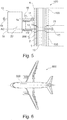
- Fig. 5 shows a water pipe system 500, which has a plurality of self-heating water pipe segments 100, which are connected to each other via corresponding connecting sleeves or connecting elements 200.
- the connecting element 200 has a plated-through hole 21, which connects the inner conductor 1 to a ground terminal 12. Furthermore, one is Through connection 17 is provided, which connects the outer conductor 3 with the control unit 13. Then a coating can be omitted inside. Leakage would then always lead to a flow of current within the leakage from the inside out.
- the control unit eg IPCU-ESW
- a plurality of temperature sensors 11 may be provided which can measure the temperature in the water-carrying line 10 and / or the temperature of one of the layers 1, 2, 3, 4.
- one of the temperature sensors via the lines 14, 15 is connected to the control or regulating device 13.
- a ground terminal 16 may be provided, which can be connected to the line 14, or line 15.
- control unit 13 may also be connected to the ground.
- Fig. 6 shows an aircraft 600, in which a self-heating water pipe system 500 is installed.
- the self-heating water conduit system 500 may be located in the fuselage and / or in the wings and / or tail of the aircraft 600.
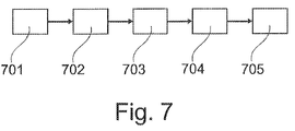
- Fig. 7 shows a flowchart of a method according to an embodiment of the invention.
- a heating element having an inner conductor, a semiconductor material and an outer conductor, which coaxially the tube enclose.
- the inner conductor can simultaneously be the water-conducting element. Before the water supply system is put into operation, it can be fitted in the aircraft and bent accordingly if it is designed to be flexible. After shaping, it can be made rigid, for example by UV curing, curing by heat or by inductive curing of the previously soft insulation jacket.
- the snap connection can be hardened before bending or consist of other material, which is more rigid.
- connection elements of the water supply system may have contacts for connection to the electrical system of the water supply system.
- fasteners may have two conically shaped end faces.
- a connecting element only has a conically shaped end face and on the other end face another connection system, for. B. a screw is used to connect the connecting element with the corresponding water pipe segment.
- the connecting elements can be designed as a tee, cross piece or Y-piece to provide ramifications in the water pipe system.
- the outer surface of the pipeline may be smooth or wavy.
- the segments can be connected to the connecting elements by means of a positive clip, cutting or clamping ring connection and this connection can be pressure-stable in the range of the required nominal pressure.
- this compound can be made detachable.
- the connection can in particular be secured against accidental release.
- the heating power of the water pipe system can be connected via a corresponding control unit 13 (see Fig. 5 ) are controlled or controlled.
- a control unit 13 controls or controlled.
- the temperature control can automatically work as frost protection or by means of temperature preselection the water temperature to a certain predetermined value.
- the heating medium itself can be used if, for example, its resistance (or other physical properties) have a corresponding temperature dependence.
- step 701 water is passed through an inner tube of a water conduit segment and a connector.
- step 702 the water temperatures in certain water pipe segments and / or connecting elements of the water pipe system are now measured.
- the measured values are then transferred to a control unit / control unit 13 in step 703.
- This unit 13 evaluates the different measured temperatures and ensures that each segment is heated accordingly, so that a desired setpoint temperature is reached. This is done in step 705.
Landscapes
- Engineering & Computer Science (AREA)
- General Engineering & Computer Science (AREA)
- Mechanical Engineering (AREA)
- Aviation & Aerospace Engineering (AREA)
- Resistance Heating (AREA)
- Pipe Accessories (AREA)
- Instantaneous Water Boilers, Portable Hot-Water Supply Apparatuses, And Control Of Portable Hot-Water Supply Apparatuses (AREA)
Description
- Die vorliegende Anmeldung beansprucht die Priorität der
US Provisional Patentanmeldung Nr. 61/312,391 10 2010 010 929.0 , eingereicht am 10. März 2010, - Die Erfindung betrifft den Frostschutz von Wasserleitungen. Insbesondere betrifft die Erfindung ein selbstheizendes Wasserleitungssegment für ein Luftfahrzeug zum Schutz vor Vereisung des Wasserleitungssegments, ein selbstheizendes Verbindungselement zum mechanischen und elektrischen Verbinden von zwei selbstheizenden Wasserleitungssegmenten, ein selbstheizendes Wasserleitungssystem für ein Luftfahrzeug, ein Luftfahrzeug mit einem selbstheizenden Wasserleitungssystem, sowie ein Verfahren zum Schutz vor Vereisung eines Wasserleitungssystems in einem Luftfahrzeug.
- Die Wasserleitungen speziell in Verkehrsflugzeugen neigen in großer Höhe bzw. beim Abstellen des Flugzeugs in kaltem Klima zum Einfrieren. Aus diesem Grund ist es oft erforderlich, diese Wasserleitungen zu beheizen oder zu drainieren.
- Für die Beheizung werden in der Regel sogenannte Heizbänder verwendet, welche aus zwei Leitern, einem dazwischen liegenden Halbleiter und einer Isolationsschicht bestehen können und in mehreren Abschnitten parallel zu den Rohrleitungen verlegt werden. Das Verlegen dieser Heizbänder ist oft zeitaufwändig und es ist erforderlich, dass das Verlegen durch geschultes Fachpersonal erfolgt.
-
DE 197 26 419 A1 undUS 6,126,483 beschreiben Heizleiter-Verbindungssysteme in einem Flugzeug. - Dokument
US 4,581,521 , welches als nächstliegender Stand der Technik angesehen wird, offenbart die Merkmale des Oberbegriffes des Anspruchs 1. - Es ist eine Aufgabe der Erfindung, einen verbesserten Frostschutz von Wasserleitungen in Luftfahrzeugen anzugeben.
- Diese Aufgabe wird durch die Merkmale der unabhängigen Patentansprüche 1 (Produkt) und 13 (Verfahren) gelöst. Weiterbildungen der Erfindung ergeben sich aus den Unteransprüchen.
- Die im Folgenden beschriebenen Ausführungsbeispiele betreffen gleichermaßen das selbstheizende Wasserleitungssegment, das selbstheizende Verbindungselement, das selbstheizende Wasserleitungssystem, das Luftfahrzeug und das Verfahren. In anderen Worten lassen die sich im Folgenden beispielweise im Hinblick auf das Wasserleitungssegment beschriebenen Merkmale auch in dem Verbindungselement implementieren, und umgekehrt.
- Gemäß einem ersten, nicht beanspruchten Aspekt ist ein selbstheizendes Wasserleitungssegment für ein Luftfahrzeug zum Schutz vor Vereisung des Wasserleitungssegments angegeben. Das Wasserleitungssegment weist ein Innenrohr sowie eine Heizvorrichtung auf. Das Innenrohr dient der Leitung von Wasser und die Heizvorrichtung, welche eine Außenfläche des Wasserleitungssegments umschließt, ist in das Wasserleitungssegment integriert und kann zum Beheizen des Innenrohrs eingesetzt werden.
- Ein Verlegen von Heizbändern ist nicht mehr erforderlich. Die verschiedenen Segmente können zu einem komplexen Wasserleitungssystem verbaut werden. Gemäß einem weiteren Aspekt der Erfindung ist ein selbstheizendes Verbindungselement zum mechanischen und elektrischen Verbinden von zwei selbstheizenden Wasserleitungssegmenten, wie sie oben und im Folgenden beschrieben werden, angegeben. Auch kann das Verbindungselement zum mechanischen und/oder elektrischen Verbinden von mehr als zwei selbstheizenden Wasserleitungssegmenten (beispielsweise T-förmig oder Y-förmig) ausgeführt sein. Gemäß einem weiteren Aspekt der Erfindung ist ein selbstheizendes Wasserleitungssystem für ein Luftfahrzeug angegeben, welches mehrere oben und im Folgenden beschriebene selbstheizende Wasserleitungssegmente und mehrere oben und im Folgenden beschriebene Verbindungselemente aufweist. Jeweils eines der Verbindungselemente verbindet hierbei mindestens jeweils zwei Wasserleitungssegmente mechanisch und elektrisch miteinander.
- Gemäß einem weiteren Aspekt der Erfindung ist ein Luftfahrzeug mit einem oben und im Folgenden beschriebenen Wasserleitungssystem angegeben.
- Gemäß einem weiteren Aspekt der Erfindung ist ein Verfahren zum Schutz vor Vereisung eines Wasserleitungssystems in einem Luftfahrzeug angegeben, bei dem Wasser durch ein Innenrohr eines Wasserleitungssegments und eines erfindungsgemäßen Verbindungselements geleitet wird. Weiterhin erfolgt ein Beheizen des Innenrohrs durch eine Heizvorrichtung, die das Wasserleitungssegment und das Verbindungselement vollständig ummantelt und in das Wasserleitungssegment und das Verbindungselement integriert ist.
- Es kann als ein Kernaspekt der Erfindung angesehen werden, dass die wasserführenden Rohrleitungen (also die Kombination aus den Wasserleitungssegmenten und den Verbindungselementen) direkt beheizt werden, da die Heizvorrichtung in der Rohrleitung integriert ist. Hierdurch kann beispielsweise der Wärmeübergang verbessert werden. Weiterhin kann die Heizleistung kontinuierlich in das gesamte Rohrsystem abgegeben werden und die örtlich tatsächlich vorhandene Heizleistung kann direkt überwacht werden. Auf diese Weise kann vermieden werden, dass die abgegebene Heizleistung höher als notwendig ausfällt, wodurch der Energieverbrauch und damit der Treibstoffbedarf des Flugzeugs reduziert werden kann.
- Da die wasserführenden Rohrleitungen direkt beheizt werden, kann die Montage vereinfacht werden. Auch kann dies zu einem verbesserten Wärmeübergang und zusätzlicher Gewichtsersparnis führen, da keine zusätzlichen Elemente installiert werden müssen. Im übrigen kann der Wärmeübertrag zwischen der Heizvorrichtung und beispielsweise dem Innenrohr optimiert werden, da die Heizvorrichtung in den Rohrleitungen integriert ist Bei geeigneter Auslegung lassen sich auf diese Weise außerdem Warmwasser- und Kaltwasserkreise realisieren, so dass Durchlauferhitzer oder Boiler eingespart werden können.
- Gemäß einer Ausführungsform der Erfindung ist die Heizvorrichtung eine Halbleiterheizvorrichtung (z.B. ein PTC (Positive Temperature Coefficient) Thermistor), die einen Innenleiter, einen Außenleiter und einen dazwischen angeordneten Halbleiter aufweist, wobei der Innenleiter, der Halbleiter und der Außenleiter koaxial zueinander angeordnet sind.
- Gemäß einer weiteren Ausführungsform der Erfindung handelt es sich bei dem Innenleiter um das Innenrohr selbst, welches dem Wassertransport dient. Das Außenrohr oder metallische Geflecht dient als AC-Leitung.
- Gegebenenfalls weist das Innenrohr eine innere, isolierende Ummantelung auf.
- Gemäß einer weiteren Ausführungsform der Erfindung weist das Wasserleitungssegment einen äußeren Isolationsmantel aus Kunststoff auf, der um den Außenleiter angeordnet ist.
- An dieser Stelle sei noch einmal darauf hingewiesen, dass die im Folgenden und oben beschriebenen Merkmale natürlich auch in dem Verbindungselement implementiert sein können. So kann das Verbindungselement ebenfalls einen Isolationsmantel aus Kunststoff aufweisen, der sich bei Installation des Systems an den entsprechenden Isolationsmantel des Wasserleitungssegments anschließt.
- Gemäß einer weiteren Ausführungsform der Erfindung kann das Wasserleitungssegment zur Montage biegsam ausgeführt sein. Insbesondere können die leitenden Schichten auch aus Geflecht sein, wobei in diesem Fall separate Stromzuführungen vorgesehen sein können.
- Weiterhin kann, gemäß einer weiteren Ausführungsform der Erfindung, der Isolationsmantel zum Aushärten nach der Montage des Wasserleitungssegments ausgeführt sein.
- Gemäß einer weiteren Ausführungsform der Erfindung weist das selbstheizende Verbindungselement einen ersten konischen Bereich an einer ersten Stirnseite des Verbindungselements auf, wobei der erste konische Bereich zur Bereitstellung einer elektrischen und einer mechanischen Verbindung zu einem ersten Wasserleitungssegment ausgeführt ist, wenn Verbindungselement und Wasserleitungssegment miteinander verbunden werden.
- Gemäß einer weiteren Ausführungsform der Erfindung weist das Verbindungselement einen zweiten konischen Bereich an einer zweiten Stirnseite des Verbindungselements auf, wobei die beiden konischen Bereiche zur Bereitstellung der elektrischen und der mechanischen Verbindung der beiden Wasserleitungssegmente ausgeführt sind. Die Wasserleitungssegmente weisen entsprechende konische Bereiche an deren Stirnseiten auf, die zum Anschluss an die konischen Bereiche der Verbindungselemente ausgeführt sind.
- Gemäß einer weiteren Ausführungsform der Erfindung weist das Verbindungselement weiterhin eine Heizvorrichtung mit einem Innenleiter, einem Außenleiter und einem dazwischen angeordneten Halbleiter auf, wobei der Innenleiter, der Halbleiter und der Außenleiter koaxial zueinander angeordnet sind.
- Bei Montage des Wasserleitungssystems werden die entsprechenden Innenleiter, Halbleiter und Außenleiter der Verbindungselemente und Wasserleitungssegmente aneinander angeschlossen.
- Gemäß einer weiteren Ausführungsform der Erfindung weist das Verbindungselement einen ersten elektrischen Anschluss auf, der zum Innenleiter führt. Weiterhin ist ein zweiter elektrischer Anschluss an den Außenleiter vorgesehen, wobei die beiden Anschlüsse zur Verbindung mit einer Steuervorrichtung ausgeführt sind, so dass über die Steuervorrichtung Strom in Innenleiter und Außenleiter eingespeist werden kann.
- Das selbstheizende Wasserleitungssystem weist, gemäß einer Ausführungsform der Erfindung, eine Vielzahl an oben und im Folgenden beschriebenen Wasserleitungssegmenten und Verbindungselementen auf, wobei die Heizvorrichtungen die Wasserleitungssegmente und die Verbindungselemente vollständig ummanteln. Insbesondere treten beispielsweise keine Diskontinuitäten an den Verbindungsbereichen zwischen den Wasserleitungssegmenten und den Verbindungselementen auf.
- Im Folgenden werden mit Verweis auf die Figuren Ausführungsbeispiele der Erfindung beschrieben.
- Kurze Beschreibung der Figuren
-
Fig. 1 zeigt zwei Ansichten eines selbstheizenden Wasserleitungssegments -
Fig. 2 zeigt zwei Ansichten eines selbstheizenden Verbindungselements gemäß einem Ausführungsbeispiel der Erfindung. -
Fig. 3 zeigt die Verbindung zwischen einem Wasserleitungssegment und einem Verbindungselement gemäß einem Ausführungsbeispiel der Erfindung, in perspektivischer Darstellung. -
Fig. 4 zeigt die Ausführung einer Clip-Verbindung zwischen einem Wasserleitungssegment und einem Verbindungselement gemäß einem Ausführungsbeispiel der Erfindung. -
Fig. 5 zeigt ein selbstheizendes Wasserleitungssystem gemäß einem Ausführungsbeispiel der Erfindung. -
Fig. 6 zeigt ein Luftfahrzeug gemäß einem Ausführungsbeispiel der Erfindung. -
Fig. 7 zeigt ein Flussdiagramm eines Verfahrens gemäß einem Ausführungsbeispiel der Erfindung. - Detaillierte Beschreibung von Ausführungsbeispielen
- Die Darstellungen in den Figuren sind schematisch und nicht maßstäblich.
- In der folgenden Figurenbeschreibung werden für die gleichen oder ähnlichen Elemente die gleichen Bezugsziffern verwendet.
-
Fig. 1 zeigt ein selbstheizendes Wasserleitungssegment 100 in Seitenansicht sowie als Schnittdarstellung entlang der Ebene A-A. -
Fig. 2 zeigt ein selbstheizendes Verbindungselement 200, ebenfalls in Seitenansicht sowie in Schnittdarstellung entlang der Schnittebene B-B. - Die Rohrleitungen (Wasserleitungssegment 100 und Verbindungselement 200) sind koaxial aufgebaut. Sie bestehen (von innen nach außen) aus einem metallischen Innenleiter 1, 1a der gleichzeitig als wasserführende Leitung dienen kann, einer Halbleiterschicht 2, 2a einem metallischen Außenleiter 3, 3a und einer Isolierschicht 4, 4a, z. B. aus einem Kunststoffmaterial.
- Weiterhin weist das Wasserleitungselement 100 in der Isolierschicht 4 eine ringförmige Ausnehmung 5 auf (eine sogenannte Clipnut), in welche eine entsprechende Cliplasche 5a des Verbindungselements eingeklickt werden kann, um das Verbindungselement 200 an das Wasserleitungssegment 100 anzuschließen und daran zu befestigen.
- Die verschiedenen Schichten 1, 1a, 2, 2a, 3, 3a, 4, 4a sind so ausgewählt und angeordnet und ihre Dicke ist so aufeinander abgestimmt, dass sich das Rohr biegen lässt. Der Kunststoff-Isoliermantel 4 kann beispielsweise aus einem UV-empfindlichen Werkstoff bestehen, der unter UV-Lichteinfluss aushärtet. Im Lieferzustand wird diese Schicht durch eine lichtundurchlässige Folie geschützt. Nach der Verformung des Rohres in seine gewünschte Gestalt wird die Schutzfolie entfernt und das Rohr mittels einer UV-Lampe gehärtet, so dass es formstabil ist.
- Die in Frage kommenden Werkstoffe für den wasserführenden Innenleiter 1 können sich nach den einschlägigen Trinkwasserbestimmungen im Sinne der folgenden Regularien und Verordnungen richten: Deutsche Trinkwasserverordnung - TrinkwV 2000; französische Trinkwasserverordnung - Qualité des eaux destinée à la consommation humaine; US-Trinkwasserverordnung Part 141 - National Primary Drinking Water Regulations; EU-Richtlinie 98/83/EG des Rates vom 3. November 1998 über die Qualität von Wasser für den menschlichen Gebrauch; ESA-Richtlinie -PSS-03-402 Issue 1 - Water Quality Standards in Manned Space Vehicles.
- Zur Verbindung und zur elektrischen Kontaktierung der Segmente dienen speziell ausgeführte Muffen (in anderen Worten die Verbindungselemente 200), die einen Innenkonus aufweisen. Alternativ können die Muffen einen Außenkonus aufweisen, in welchem Fall dann die entsprechende Stirnfläche des Wasserleitungssegments 100 einen Innenkonus besitzt. Innerhalb dieser Muffen befinden sich O-Ringe 7a zur Abdichtung des Systems gegen Wasseraustritt. Die Muffen 200 haltern die Rohre 100 mittels einer raumschlüssigen Clip-, Schneid- oder Klemmringverbindung.
- Die Bezugszeichen 6 bzw. 6a zeigen den Anlagekonus des rohrförmigen Wasserleitungssegments 100 bzw. den entsprechenden Anlagekonus der Muffe 200.
- Das Bezugszeichen 7 weist auf die Stirnfläche des Wasserleitungssegments 100 und dort auf den Innenleiter 1, wo sich die Anlagefläche für den O-Ring 7a der Muffe 200 befindet.
- Das muffenartige Verbindungssegment 200 kann sowohl an der linken Stirnfläche 201 als auch an seiner rechten Stirnfläche 202 mit einem entsprechenden Wasserleitungssegment 100 verbunden werden.
- Die Wasserleitungssegmente 100 können auf jede beliebige Länge zugeschnitten werden. Für die Muffenverbindung werden die Enden der Wasserleitungssegmente in einer Vorrichtung konusförmig angefast. Dieses Anfasen erfolgt beispielsweise durch Fräsen oder Drehen.
- Der elektrische Kontakt zwischen den einzelnen Schichten 1, 1a; 2, 2a bzw. 3, 3a wird über eine Verzahnung innerhalb des Muffenkonus 200 ausgeführt, welcher sich beim Zusammenfügen der beiden Bauteile in die angefasten Flächen des Innenleiters und des Außenleiters der Rohre drückt.
- An dieser Stelle ist zu beachten, dass die einzelnen Wasserleitungssegmente durchgängige Schichten 1, 2, 3, 4 aufweisen können. Auch ist es möglich, dass die Heizelementschichten 1, 2, 3 in getrennten Segmenten ausgeführt sind, welche voneinander isoliert sind, eigene elektrische Anschlüsse und unterschiedliche Schichtdicken aufweisen können. Auf diese Weise ist es möglich, verschiedene Rohrsegmente unterschiedlich stark zu heizen, je nach Temperaturprofil. Diese individuelle Beheizung verschiedener Rohrsegmente kann über eine entsprechende Steuereinheit 13 in Verbindung mit Temperatursensoren 11 (siehe
Fig. 5 ) erfolgen. -
Fig. 3 zeigt eine Verbindung zwischen einer Muffe 200 und einem Wasserleitungssegment 100 in perspektivischer Darstellung. Insbesondere ist zu erkennen, dass die Muffe (also das Verbindungselement 200) einen etwas größeren Durchmesser aufweist, als das Wasserleitungssegment (Rohr) 100. Auf der Innenfläche der konischen Ausnehmung 6a des Verbindungselements 200 liegen mehrere Cliplaschen 5a, welche in die entsprechende Clipnut 5 des Wasserleitungssegments 100 eingreifen, wenn die beiden Elemente zusammengedrückt werden. - Weiterhin sind mehrere Kontaktflächen (die beim Anfasen entstehen) 8 vorgesehen, welche beim Zusammenfügen von Wasserleitungssegment und Verbindungselement die entsprechende Schicht 1, 2, 3 des Wasserleitungssegments 100 kontaktieren. Diese Kontaktflächen sind mit elektrischen Durchführungen verbunden, welche durch den Körper des Verbindungselements 200 nach außen führen, so dass daran dann eine Regeleinheit bzw. eine Steuereinheit 13 angeschlossen werden kann. Wenn beispielsweise der Aufbau bzw. die Anzahl der Schichten komplex wird, kann die Sensorzuleitung separat geführt sein.
- Weiterhin können Ausnehmungen für ein Ausrückwerkzeug vorgesehen sein, mit deren Hilfe das Wasserleitungssegment vom Verbindungselement getrennt werden kann.
-
Fig. 4 zeigt eine Detaildarstellung der Clip-Verbindung im Querschnitt. Das Wasserleitungssegment 100 weist eine Clipnut 5 auf, in welche eine entsprechende Cliplasche 5a des Verbindungselements 200 eingreift, wenn das Verbindungselement 200 über die Stirnseite des Wasserleitungssegments 100 geschoben wurde. -
Fig. 5 zeigt ein Wasserleitungssystem 500, welches mehrere selbstheizende Wasserleitungssegmente 100 aufweist, die über entsprechende Anschlussmuffen bzw. Verbindungselemente 200 miteinander verbunden sind. - Das Verbindungselement 200 weist eine Durchkontaktierung 21 auf, welche den Innenleiter 1 mit einem Masseanschluss 12 verbindet. Weiterhin ist eine Durchkontaktierung 17 vorgesehen, welche den Außenleiter 3 mit der Steuer- bzw. Regeleinheit 13 verbindet. Dann kann auch eine Beschichtung innen entfallen. Eine Leckage würde dann auch immer zu einem Stromfluss innerhalb der Leckage von innen nach außen führen. Die Steuer- bzw. Regeleinheit (z. B. IPCU-ESW) weist einen Schalter 22 auf, der über die Leitung 18 eine Verbindung zwischen dem Innenleiter und einer Wechselstromquelle herstellen kann.
- Weiterhin können mehrere Temperatursensoren 11 vorgesehen sein, welche die Temperatur in der wasserführenden Leitung 10 und/oder die Temperatur einer der Schichten 1, 2, 3, 4 messen können. Hierfür ist einer der Temperatursensoren über die Leitungen 14, 15 an die Steuer- bzw. Regelungsvorrichtung 13 angeschlossen. Auch kann ein Masseanschluss 16 vorgesehen sein, der mit der Leitung 14, oder Leitung 15 verbunden werden kann.
- Über die Leitung 19 kann die Steuer- bzw. Regelungseinheit 13 ebenfalls an die Masse angeschlossen sein.
- Auf diese Weise ist es möglich, eine durchgängig beheizte Rohrleitung bereitzustellen.
-
Fig. 6 zeigt ein Luftfahrzeug 600, in welches ein selbstheizendes Wasserleitungssystem 500 eingebaut ist. Das selbstheizende Wasserleitungssystem 500 kann sich im Rumpf und/oder in den Tragflächen und/oder im Leitwerk des Luftfahrzeugs 600 befinden. -
Fig. 7 zeigt ein Flussdiagramm eines Verfahrens gemäß einem Ausführungsbeispiel der Erfindung. Es ist ein Heizelement vorgesehen, welches einen Innenleiter, ein Halbleitermaterial und einen Außenleiter aufweist, welche das Rohr koaxial umschließen. Der Innenleiter kann gleichzeitig das wasserführende Element sein. Bevor das Wasserleitungssystem in Betrieb genommen wird, kann es, wenn es biegeweich ausgeführt ist, im Flugzeug eingepasst und entsprechend gebogen werden. Nach der Formgebung kann es biegesteif gemacht werden, beispielsweise mittels UV-Aushärtung, Aushärtung durch Wärme oder mittels einer induktiven Aushärtung des vorher weichen Isolationsmantels. - Bei der biegeweichen Ausführung kann die Snapverbindung vor dem Biegen gehärtet werden oder aus anderem Material bestehen, welches biegesteifer ist.
- Nach dem Aushärten des Kunststoff-Isolationsmantels erhält das Rohr seine maximale Druckfestigkeit. Durch das Zusammenstecken der Wasserleitungssegmente und der Verbindungselemente erfolgt sowohl eine mechanische als auch eine elektrische Kontaktierung des Rohres bzw. der einzelnen Schichten der Wasserleitungssegmente. Bestimmte Verbindungselemente des Wasserleitungssystems können Kontakte zum Anschluss an das elektrische System des Wasserleitungssystems aufweisen.
- Nicht alle Verbindungselemente weisen unter Umständen zwei konisch geformte Stirnseiten auf. Beispielsweise ist es möglich, dass ein Verbindungselement nur eine konisch geformte Stirnseite aufweist und auf der anderen Stirnseite ein anderweitiges Verbindungssystem, z. B. eine Verschraubung eingesetzt wird, um das Verbindungselement mit dem entsprechenden Wasserleitungssegment zu verbinden.
- Weiterhin können die Verbindungselemente als T-Stück, Kreuzstück oder Y-Stück ausgeführt sein, um Verästelungen im Wasserleitungssystem bereitzustellen. Insbesondere kann die äußere Oberfläche der Rohrleitung glatt oder gewellt sein. Die Segmente können mit den Verbindungselementen mittels einer formschlüssigen Clip-, Schneid- oder Klemmringverbindung verbunden werden und diese Verbindung kann druckstabil im Bereich des geforderten Nenndrucks sein. Insbesondere kann diese Verbindung lösbar ausgeführt sein. Die Verbindung kann insbesondere auch gegen versehentliches Lösen gesichert sein.
- Die Heizleistung des Wasserleitungssystems kann über eine entsprechende Regel-oder Steuereinheit 13 (siehe
Fig. 5 ) geregelt oder gesteuert werden. Es können Temperaturfühler 11 vorgesehen sein, die die Wassertemperatur und/oder die Temperatur einer der Schichten kontinuierlich messen. Die Temperaturregelung kann automatisch als Frostschutz arbeiten oder mittels Temperaturvorwahl die Wassertemperatur auf einen bestimmten vorgegebenen Wert einstellen. Als Temperatursensor kann das Heizmedium selbst verwendet werden, falls zum Beispiel dessen Widerstand (oder andere physikalischen Eigenschaften) eine entsprechende Temperaturabhängigkeit aufweisen. - Zunächst einmal wird in Schritt 701 Wasser durch ein Innenrohr eines Wasserleitungssegments und eines Verbindungselements geleitet. In Schritt 702 werden nun die Wassertemperaturen in bestimmten Wasserleitungssegmenten und/oder Verbindungselementen des Wasserleitungssystems gemessen. Die Messwerte werden dann in Schritt 703 an eine Steuereinheit/Regeleinheit 13 übergeben. Diese Einheit 13 wertet die verschiedenen gemessenen Temperaturen aus und stellt sicher, dass jedes Segment entsprechend beheizt wird, so dass eine gewünschte Solltemperatur erreicht wird. Dies erfolgt in Schritt 705.
- Im Übrigen sei darauf hingewiesen, dass "umfassend" und "aufweisend" keine anderen Elemente oder Schritte ausschließt und "eine" oder "ein" keine Vielzahl ausschließt. Ferner sei darauf hingewiesen, dass Merkmale oder Schritte, die mit Verweis auf eines der obigen Ausführungsbeispiele beschrieben worden sind, auch in Kombination mit anderen Merkmalen oder Schritten anderer oben beschriebener Ausführungsbeispiele verwendet werden können. Bezugszeichen in den Ansprüchen sind nicht als Einschränkungen anzuschen.
-
- 1
- Innenteiterrohr
- 1a
- Innenleitermuffe
- 2
- Halbleiterrohr
- 2a
- Halbleitermuffe
- 3
- Außenleiterrohr
- 3a
- Außenleitermuffe
- 4
- Isolierung Rohr
- 4a
- Isolierung Muffe
- 5
- Clipnut Rohr
- 5a
- Cliplasche Muffe
- 6
- Anlagekonus Rohr
- 6a
- Anlagekonus Muffe
- 7
- Anlagefläche O-Ring
- 7a
- O-Ring
- 8
- Kantaktspitze
- 100
- Wasserleitungssegment
- 200
- Verbindungselement
- 10
- wasserführende Leitung
- 11
- Temperatursensor
- 12
- Masse
- 13
- Regel- oder Steuereinheit
- 14
- erste Leitung Temperatursensor
- 15
- zweite Leitung Temperatursensor
- 16
- Masse
- 17
- Anschluss Innenleiter
- 18
- AC-Anschluss für die Regel- oder Steuereinheit
- 19
- Masse
- 20
- Anschluss Außenleiter
- 21
- Durchkontaktierung
- 22
- Schalter
Claims (13)
- Selbstheizendes Verbindungselement (200) zum mechanischen und elektrischen Verbinden von zwei selbstheizenden Wasserleitungssegmenten (100) für ein Luftfahrzeug zum Schutz vor Vereisung des Wasserleitungssegments, die beiden Wasserleitungssegmente aufweisend: ein Innenrohr zur Leitung von Wasser; eine Heizvorrichtung, die eine Außenfläche des Wasserleitungssegments umschließt; wobei die Heizvorrichtung in das Wasserleitungssegment integriert ist, das Verbindungselement aufweisend eine Heizvorrichtung mit einem Innenleiter (1a), einem Außenleiter (3a) und einem dazwischen angeordneten Halbleiter (2a); dadurch gekennzeichnet, dass der Innenleiter (1a), der Halbleiter (2a) und der Außenleiter (3a) koaxial zueinander angeordnet sind;
- Selbstheizendes Verbindungselement (200)nach Anspruch 1,wobei die Heizvorrichtung (1, 2, 3) beider Wasserleitungssegmente eine Halbleiterheizvorrichtung ist, die einen Innenleiter (1), einen Außenleiter (3) und einen dazwischen angeordneten Halbleiter (2) aufweist;wobei der Innenleiter (1), der Halbleiter (2) und der Außenleiter (3) koaxial zueinander angeordnet sind.
- Selbstheizendes Verbindungselement (200)nach Anspruch 2,wobei der Innenleiter (1) jedes der Wasserleitungssegmente das Innenrohr (1) ist.
- Selbstheizendes Verbindungselement (200)nach Anspruch 2 oder 3, beide Wasserleitungssegmente weiterhin aufweisend:einen Isolationsmantel (4) aus Kunststoff, der um den Außenleiter (3) angeordnet ist.
- Selbstheizendes Verbindungselement (200)nach einem der vorhergehenden Ansprüche,wobei beide Wasserleitungssegmente (100) und das Verbindungselement zur Montage biegsam ausgeführt sind; undwobei die leitenden Schichten des Verbindungselements jeweils aus einem Geflecht bestehen.
- Selbstheizendes Verbindungselement (200)nach einem der Ansprüche 4 oder 5,wobei der Isolationsmantel (4) zum Aushärten nach der Montage des Wasserleitungssegments (100) ausgeführt ist.
- Selbstheizendes Verbindungselement (200) nach einem der vorhergehenden Ansprüche, aufweisend:einen ersten konischen Bereich (201) an einer ersten Stirnseite des Verbindungselements (200);wobei der erste konische Bereiche (201) zur Bereitstellung einer elektrischen und einer mechanischen Verbindung zu einem ersten Wasserleitungssegment (100) ausgeführt ist.
- Selbstheizendes Verbindungselement (200) nach Anspruch 7, weiterhin aufweisend:einen zweiten konischen Bereich (202) an einer zweiten Stirnseite des Verbindungselements (200),wobei die beiden konischen Bereiche (201, 202) zur Bereitstellung der elektrischen und der mechanischen Verbindung der beiden Wasserleitungssegmente (100) ausgeführt sind.
- Selbstheizendes Verbindungselement (200) nach einem der vorhergehenden Ansprüche, weiterhin aufweisend:einen ersten elektrischen Anschluss (17) an den Innenleiter (1a);einen zweiten elektrischen Anschluss (21) an den Außenleiter (3 a);wobei die beiden Anschlüsse zur Verbindung mit einer Steuervorrichtung (11, 13) ausgeführt sind.
- Selbstheizendes Wasserleitungssystem (500) für ein Luftfahrzeug, das Wasserleitungssystem (500) aufweisend:eine Vielzahl an selbstheizenden Wasserleitungssegmenten (100) mit jeweils:einem Innenrohr (1) zur Leitung von Wasser;einer Heizvorrichtung (1, 2, 3), die eine Außenfläche des Wasserleitungssegments (100) umschließt;wobei die Heizvorrichtung (1, 2, 3) in das Wasserleitungssegment (100) integriert ist;eine Vielzahl an Verbindungselementen (200) nach einem der Ansprüche 1 bis 9;wobei jeweils eines der Verbindungselemente (200) mindestens jeweils zwei Wasserleitungssegmente (100) mechanisch und elektrisch miteinander verbindet.
- Selbstheizendes Wasserleitungssystem (500) nach Anspruch 10,wobei die Heizvorrichtungen (1, 2, 3, 1a, 2a, 3a) die Wasserleitungssegmente (100) und die Verbindungselemente (200) vollständig ummanteln.
- Luftfahrzeug (600) mit einem Wasserleitungssystem (500) nach Anspruch 10 oder 11.
- Verfahren zum Schutz vor Vereisung eines Wasserleitungssystems in einem Luftfahrzeug gemäß Anspruch 12, das Verfahren aufweisend die Schritte:Leiten von Wasser durch ein Innenrohr (1, 1a) eines Wasserleitungssegments (100) und eines Verbindungselements (200);Beheizen des Innenrohrs (1, 1a) durch eine Heizvorrichtung (1, 2, 3, 1a, 2a, 3a);wobei die Heizvorrichtung (1, 2, 3, 1a, 2a, 3a) das Wasserleitungssegment (100) und das Verbindungselement (200) vollständig ummantelt;wobei die Heizvorrichtung (1, 2, 3, 1a, 2a, 3a) in das Wasserleitungssegment (100) und das Verbindungselement (200) integriert ist.
Applications Claiming Priority (3)
| Application Number | Priority Date | Filing Date | Title |
|---|---|---|---|
| US31239110P | 2010-03-10 | 2010-03-10 | |
| DE201010010929 DE102010010929A1 (de) | 2010-03-10 | 2010-03-10 | Schutz von Wasserleitungen gegen Frost |
| PCT/EP2011/052266 WO2011110408A2 (de) | 2010-03-10 | 2011-02-16 | Schutz von wasserleitungen gegen frost |
Publications (2)
| Publication Number | Publication Date |
|---|---|
| EP2544949A2 EP2544949A2 (de) | 2013-01-16 |
| EP2544949B1 true EP2544949B1 (de) | 2016-06-29 |
Family
ID=44507807
Family Applications (1)
| Application Number | Title | Priority Date | Filing Date |
|---|---|---|---|
| EP11705500.4A Not-in-force EP2544949B1 (de) | 2010-03-10 | 2011-02-16 | Schutz von wasserleitungen gegen frost |
Country Status (4)
| Country | Link |
|---|---|
| US (1) | US8820362B2 (de) |
| EP (1) | EP2544949B1 (de) |
| DE (1) | DE102010010929A1 (de) |
| WO (1) | WO2011110408A2 (de) |
Families Citing this family (18)
| Publication number | Priority date | Publication date | Assignee | Title |
|---|---|---|---|---|
| FR2994593B1 (fr) * | 2012-08-20 | 2014-09-05 | Technip France | Raccord intermediaire de connexion d'elements de conduite rigide de transport de fluide, reseau de conduites et procede d'assemblage associes |
| FR3015171B1 (fr) | 2013-12-12 | 2016-01-01 | Total Sa | Procede pour former une connexion electrique |
| FR3014737A1 (fr) * | 2013-12-12 | 2015-06-19 | Total Sa | Bande composite et procedes pour former une jonction entre deux conduites |
| FR3015172B1 (fr) | 2013-12-12 | 2019-05-10 | Total Sa | Dispositif de chauffage electrique |
| BE1021364B1 (nl) * | 2013-12-17 | 2015-11-06 | Atlas Copco Airpower Naamloze Vennootschap | Koppeling voor het verbinden van buisuiteinden en overbrugging voor gebruik in een koppeling |
| DE102014209113A1 (de) * | 2014-05-14 | 2015-11-19 | BSH Hausgeräte GmbH | Verriegelungseinrichtung zum Verriegeln einer Tür eines Haushaltsgeräts, Haushaltsgerät und entsprechendes Verfahren |
| EP3086011B1 (de) | 2015-04-21 | 2019-07-31 | Airbus Operations GmbH | Doppelwandiges rohr mit integrierter heizfähigkeit für ein luft- oder raumfahrzeug |
| FR3045772B1 (fr) | 2015-12-18 | 2018-06-01 | Stelia Aerospace | Raccord de connexion pour canalisation de circuit de fluide d’aeronef, canalisation et procede de raccordement |
| DE102016210962A1 (de) | 2016-06-20 | 2017-12-21 | Airbus Operations Gmbh | Heizbandhalbzeug sowie Heizbandvorrichtung |
| DE102016213646B4 (de) | 2016-07-26 | 2026-03-05 | Airbus Operations Gmbh | Heizbandvorrichtung und Verfahren zur Überwachung der Funktionsfähigkeit der Heizbandvorrichtung |
| GB2553846B (en) * | 2016-09-19 | 2020-10-14 | Equinor Energy As | Umbilical fluid line and umbilical |
| DE102016117830A1 (de) * | 2016-09-21 | 2018-03-22 | Voss Automotive Gmbh | Steckverbinderanordnung für Medienleitungen sowie Verfahren zum Verbinden von Medienleitungen |
| US10579080B2 (en) | 2018-04-06 | 2020-03-03 | Simmonds Precision Products, Inc. | Intelligent ice protection network |
| US10932326B2 (en) | 2018-05-24 | 2021-02-23 | Goodrich Aerospace Services Private Limited | Flexible heated hose assembly with printed positive temperature co-efficient heater |
| US11903101B2 (en) | 2019-12-13 | 2024-02-13 | Goodrich Corporation | Internal heating trace assembly |
| CN114060639B (zh) * | 2021-11-16 | 2023-03-10 | 中国商用飞机有限责任公司 | 一种飞行器管道加热控制方法、管道加热系统及飞机 |
| US12366421B2 (en) * | 2023-02-09 | 2025-07-22 | Hamilton Sundstrand Corporation | Thermally adaptive flow conduit |
| EP4458673A1 (de) * | 2023-05-03 | 2024-11-06 | Airbus Operations GmbH | Wasserversorgungssystem zur verwendung in einem flugzeug und verfahren zur verhinderung des gefrierens von wasserleitungen |
Family Cites Families (20)
| Publication number | Priority date | Publication date | Assignee | Title |
|---|---|---|---|---|
| US3378673A (en) * | 1965-10-18 | 1968-04-16 | Thomas O. Hopper | Electrically heated hose assembly |
| US4581521A (en) * | 1980-08-28 | 1986-04-08 | Grise Frederick Gerard J | Electrically heated pipe assembly |
| US4447707A (en) * | 1981-12-22 | 1984-05-08 | Nordson Corporation | Electrically heated multi-section hose having electrically heated hose joints |
| US4791277A (en) * | 1987-02-09 | 1988-12-13 | Montierth Garry L | Heating and insulation arrangement for a network of installed pipes and method |
| US4874925A (en) * | 1987-06-01 | 1989-10-17 | Dickenson Wilk A | Electrically heated hose assembly for conveying electrically conductive liquids |
| FR2662229B1 (fr) * | 1990-05-17 | 1992-07-31 | Coflexip | Conduite tubulaire flexible comportant des moyens de chauffage incorpores. |
| BR9005628C1 (pt) * | 1990-11-07 | 2000-01-25 | Petroleo Brasileiro Sa | Método de desobstrução de linhas flexìveis submarinas. |
| JPH06147390A (ja) * | 1992-11-11 | 1994-05-27 | Shinko Pantec Co Ltd | 純水加熱装置 |
| JP3640699B2 (ja) * | 1995-04-28 | 2005-04-20 | 積水化成品工業株式会社 | ヒータおよびその製造方法 |
| US5910266A (en) * | 1997-05-28 | 1999-06-08 | The B.F. Goodrich Company | Helical electrical heater |
| DE19726419A1 (de) | 1997-06-23 | 1999-01-28 | Daimler Benz Aerospace Airbus | Heizleiter-Verbindungssystem in einem Flugzeug |
| US5933574A (en) * | 1998-02-09 | 1999-08-03 | Avansino; Gary L. | Heated fluid conduit |
| US6211494B1 (en) * | 1999-08-25 | 2001-04-03 | The B. F. Goodrich Company | Drainmast with integral electronic temperature control |
| US7555349B2 (en) * | 2000-09-26 | 2009-06-30 | Advanced Neuromodulation Systems, Inc. | Lead body and method of lead body construction |
| US6792200B2 (en) * | 2002-04-04 | 2004-09-14 | Arizona Public Service Company, Inc. | System and method for a pre-fabricated heat-traced header |
| GB0219373D0 (en) * | 2002-08-20 | 2002-09-25 | Heat Trace Ltd | Heated conduit |
| FR2874075B1 (fr) * | 2004-08-03 | 2007-11-09 | Espa Sarl | Tube de transport de fluide |
| DE202005004602U1 (de) * | 2005-03-18 | 2005-07-14 | Eichenauer Heizelemente Gmbh & Co. Kg | Beheizte Flüssigkeitsleitung |
| US8291939B2 (en) * | 2005-07-29 | 2012-10-23 | Sykes Hollow Innovations, Ltd. | Grounding system for a heated hose |
| DE102009008304A1 (de) * | 2008-10-15 | 2010-04-29 | Eads Deutschland Gmbh | Beheizbare Rohrleitung |
-
2010
- 2010-03-10 DE DE201010010929 patent/DE102010010929A1/de not_active Ceased
-
2011
- 2011-02-16 EP EP11705500.4A patent/EP2544949B1/de not_active Not-in-force
- 2011-02-16 WO PCT/EP2011/052266 patent/WO2011110408A2/de not_active Ceased
-
2012
- 2012-09-10 US US13/607,948 patent/US8820362B2/en active Active
Also Published As
| Publication number | Publication date |
|---|---|
| DE102010010929A1 (de) | 2011-09-15 |
| WO2011110408A3 (de) | 2011-11-10 |
| US20130048128A1 (en) | 2013-02-28 |
| EP2544949A2 (de) | 2013-01-16 |
| WO2011110408A2 (de) | 2011-09-15 |
| US8820362B2 (en) | 2014-09-02 |
Similar Documents
| Publication | Publication Date | Title |
|---|---|---|
| WO2011110408A2 (de) | Schutz von wasserleitungen gegen frost | |
| DE102010019777B4 (de) | Luftfahrzeug mit einem Fluidleitungssystem | |
| EP2926067B1 (de) | Wärmetauscher | |
| DE112008003310T5 (de) | Heizrohrleitung für den Transport von Fluid | |
| EP2676524B1 (de) | Transparente scheibe mit elektrischer heizschicht, sowie herstellungsverfahren hierfür | |
| DE102010051550A1 (de) | Konfektionierte elektrisch beheizbare Medienleitung sowie Verfahren zum Herstellen einer solchen Medienleitung | |
| DE3414284C2 (de) | ||
| EP2894719B2 (de) | Vorrichtung zur Ableitung eines Kurzschlussstroms | |
| DE112015003026T5 (de) | Selbstregulierende Inline-Heizvorrichtung | |
| EP1610049B1 (de) | Schlauchverbindungssystem für einen beheizbaren Schlauch | |
| DE102016113484A9 (de) | Transportleitung für Scheibenwaschflüssigkeit reduzierter Größe, die mit zumindest einem Koaxialkabel ausgestattet ist | |
| EP3477178B1 (de) | Beheizbarer flexibler schlauch mit aufgebrachtem heizelement | |
| EP3234434B1 (de) | Beheizbare medienleitung sowie verfahren zum herstellen einer beheizbaren medienleitung | |
| DE102011086212B4 (de) | Vorrichtung zur Verbindung zweier elektrischer Leitungen | |
| DE102016213646B4 (de) | Heizbandvorrichtung und Verfahren zur Überwachung der Funktionsfähigkeit der Heizbandvorrichtung | |
| EP4026400B1 (de) | Werkzeugvorrichtung mit einer heizmatte sowie reparaturverfahren und herstellverfahren für werkstücke aus kunststoffmaterial | |
| DE102016118931A1 (de) | Medienleitung | |
| EP4112446B1 (de) | Abflussmast | |
| DE19804179A1 (de) | Beheizbares Sandauslaufrohr für Schienenfahrzeuge und Verfahren zu dessen Herstellung | |
| EP2182268A1 (de) | Heiz- oder Kühlanordnung für eine Rohrleitung | |
| EP2873513B1 (de) | Elektroschweissrohrverbindungsformteil | |
| EP2287540A2 (de) | Flüssigkeitserhitzer | |
| EP2876273B1 (de) | Verbindungsaggregat aus einer beheizbaren Kraftfahrzeugleitung und einem beheizbaren Verbinder | |
| EP3992991A1 (de) | Durchführungsanordnung sowie verfahren zu deren herstellung, transformator und verwendung | |
| DE29815001U1 (de) | Wärmeisolierte Rohre |
Legal Events
| Date | Code | Title | Description |
|---|---|---|---|
| PUAI | Public reference made under article 153(3) epc to a published international application that has entered the european phase |
Free format text: ORIGINAL CODE: 0009012 |
|
| 17P | Request for examination filed |
Effective date: 20120910 |
|
| AK | Designated contracting states |
Kind code of ref document: A2 Designated state(s): AL AT BE BG CH CY CZ DE DK EE ES FI FR GB GR HR HU IE IS IT LI LT LU LV MC MK MT NL NO PL PT RO RS SE SI SK SM TR |
|
| DAX | Request for extension of the european patent (deleted) | ||
| REG | Reference to a national code |
Ref country code: DE Ref legal event code: R079 Ref document number: 502011010036 Country of ref document: DE Free format text: PREVIOUS MAIN CLASS: B64D0011020000 Ipc: F16L0037098000 |
|
| RIC1 | Information provided on ipc code assigned before grant |
Ipc: F16L 25/01 20060101ALI20151127BHEP Ipc: F16L 53/00 20060101ALI20151127BHEP Ipc: B64D 11/02 20060101ALI20151127BHEP Ipc: F16L 37/098 20060101AFI20151127BHEP |
|
| GRAP | Despatch of communication of intention to grant a patent |
Free format text: ORIGINAL CODE: EPIDOSNIGR1 |
|
| INTG | Intention to grant announced |
Effective date: 20160118 |
|
| GRAS | Grant fee paid |
Free format text: ORIGINAL CODE: EPIDOSNIGR3 |
|
| GRAA | (expected) grant |
Free format text: ORIGINAL CODE: 0009210 |
|
| AK | Designated contracting states |
Kind code of ref document: B1 Designated state(s): AL AT BE BG CH CY CZ DE DK EE ES FI FR GB GR HR HU IE IS IT LI LT LU LV MC MK MT NL NO PL PT RO RS SE SI SK SM TR |
|
| REG | Reference to a national code |
Ref country code: GB Ref legal event code: FG4D Free format text: NOT ENGLISH |
|
| REG | Reference to a national code |
Ref country code: CH Ref legal event code: EP |
|
| REG | Reference to a national code |
Ref country code: AT Ref legal event code: REF Ref document number: 809384 Country of ref document: AT Kind code of ref document: T Effective date: 20160715 |
|
| REG | Reference to a national code |
Ref country code: IE Ref legal event code: FG4D Free format text: LANGUAGE OF EP DOCUMENT: GERMAN |
|
| REG | Reference to a national code |
Ref country code: DE Ref legal event code: R096 Ref document number: 502011010036 Country of ref document: DE |
|
| REG | Reference to a national code |
Ref country code: LT Ref legal event code: MG4D |
|
| PG25 | Lapsed in a contracting state [announced via postgrant information from national office to epo] |
Ref country code: LT Free format text: LAPSE BECAUSE OF FAILURE TO SUBMIT A TRANSLATION OF THE DESCRIPTION OR TO PAY THE FEE WITHIN THE PRESCRIBED TIME-LIMIT Effective date: 20160629 Ref country code: FI Free format text: LAPSE BECAUSE OF FAILURE TO SUBMIT A TRANSLATION OF THE DESCRIPTION OR TO PAY THE FEE WITHIN THE PRESCRIBED TIME-LIMIT Effective date: 20160629 Ref country code: NO Free format text: LAPSE BECAUSE OF FAILURE TO SUBMIT A TRANSLATION OF THE DESCRIPTION OR TO PAY THE FEE WITHIN THE PRESCRIBED TIME-LIMIT Effective date: 20160929 |
|
| REG | Reference to a national code |
Ref country code: NL Ref legal event code: MP Effective date: 20160629 |
|
| PG25 | Lapsed in a contracting state [announced via postgrant information from national office to epo] |
Ref country code: RS Free format text: LAPSE BECAUSE OF FAILURE TO SUBMIT A TRANSLATION OF THE DESCRIPTION OR TO PAY THE FEE WITHIN THE PRESCRIBED TIME-LIMIT Effective date: 20160629 Ref country code: NL Free format text: LAPSE BECAUSE OF FAILURE TO SUBMIT A TRANSLATION OF THE DESCRIPTION OR TO PAY THE FEE WITHIN THE PRESCRIBED TIME-LIMIT Effective date: 20160629 Ref country code: LV Free format text: LAPSE BECAUSE OF FAILURE TO SUBMIT A TRANSLATION OF THE DESCRIPTION OR TO PAY THE FEE WITHIN THE PRESCRIBED TIME-LIMIT Effective date: 20160629 Ref country code: SE Free format text: LAPSE BECAUSE OF FAILURE TO SUBMIT A TRANSLATION OF THE DESCRIPTION OR TO PAY THE FEE WITHIN THE PRESCRIBED TIME-LIMIT Effective date: 20160629 Ref country code: HR Free format text: LAPSE BECAUSE OF FAILURE TO SUBMIT A TRANSLATION OF THE DESCRIPTION OR TO PAY THE FEE WITHIN THE PRESCRIBED TIME-LIMIT Effective date: 20160629 Ref country code: GR Free format text: LAPSE BECAUSE OF FAILURE TO SUBMIT A TRANSLATION OF THE DESCRIPTION OR TO PAY THE FEE WITHIN THE PRESCRIBED TIME-LIMIT Effective date: 20160930 |
|
| PG25 | Lapsed in a contracting state [announced via postgrant information from national office to epo] |
Ref country code: SK Free format text: LAPSE BECAUSE OF FAILURE TO SUBMIT A TRANSLATION OF THE DESCRIPTION OR TO PAY THE FEE WITHIN THE PRESCRIBED TIME-LIMIT Effective date: 20160629 Ref country code: EE Free format text: LAPSE BECAUSE OF FAILURE TO SUBMIT A TRANSLATION OF THE DESCRIPTION OR TO PAY THE FEE WITHIN THE PRESCRIBED TIME-LIMIT Effective date: 20160629 Ref country code: IT Free format text: LAPSE BECAUSE OF FAILURE TO SUBMIT A TRANSLATION OF THE DESCRIPTION OR TO PAY THE FEE WITHIN THE PRESCRIBED TIME-LIMIT Effective date: 20160629 Ref country code: CZ Free format text: LAPSE BECAUSE OF FAILURE TO SUBMIT A TRANSLATION OF THE DESCRIPTION OR TO PAY THE FEE WITHIN THE PRESCRIBED TIME-LIMIT Effective date: 20160629 Ref country code: RO Free format text: LAPSE BECAUSE OF FAILURE TO SUBMIT A TRANSLATION OF THE DESCRIPTION OR TO PAY THE FEE WITHIN THE PRESCRIBED TIME-LIMIT Effective date: 20160629 Ref country code: IS Free format text: LAPSE BECAUSE OF FAILURE TO SUBMIT A TRANSLATION OF THE DESCRIPTION OR TO PAY THE FEE WITHIN THE PRESCRIBED TIME-LIMIT Effective date: 20161029 |
|
| REG | Reference to a national code |
Ref country code: FR Ref legal event code: PLFP Year of fee payment: 7 |
|
| PG25 | Lapsed in a contracting state [announced via postgrant information from national office to epo] |
Ref country code: SM Free format text: LAPSE BECAUSE OF FAILURE TO SUBMIT A TRANSLATION OF THE DESCRIPTION OR TO PAY THE FEE WITHIN THE PRESCRIBED TIME-LIMIT Effective date: 20160629 Ref country code: ES Free format text: LAPSE BECAUSE OF FAILURE TO SUBMIT A TRANSLATION OF THE DESCRIPTION OR TO PAY THE FEE WITHIN THE PRESCRIBED TIME-LIMIT Effective date: 20160629 Ref country code: PT Free format text: LAPSE BECAUSE OF FAILURE TO SUBMIT A TRANSLATION OF THE DESCRIPTION OR TO PAY THE FEE WITHIN THE PRESCRIBED TIME-LIMIT Effective date: 20161031 Ref country code: PL Free format text: LAPSE BECAUSE OF FAILURE TO SUBMIT A TRANSLATION OF THE DESCRIPTION OR TO PAY THE FEE WITHIN THE PRESCRIBED TIME-LIMIT Effective date: 20160629 |
|
| REG | Reference to a national code |
Ref country code: DE Ref legal event code: R097 Ref document number: 502011010036 Country of ref document: DE |
|
| PLBE | No opposition filed within time limit |
Free format text: ORIGINAL CODE: 0009261 |
|
| STAA | Information on the status of an ep patent application or granted ep patent |
Free format text: STATUS: NO OPPOSITION FILED WITHIN TIME LIMIT |
|
| PG25 | Lapsed in a contracting state [announced via postgrant information from national office to epo] |
Ref country code: BE Free format text: LAPSE BECAUSE OF NON-PAYMENT OF DUE FEES Effective date: 20170228 Ref country code: DK Free format text: LAPSE BECAUSE OF FAILURE TO SUBMIT A TRANSLATION OF THE DESCRIPTION OR TO PAY THE FEE WITHIN THE PRESCRIBED TIME-LIMIT Effective date: 20160629 |
|
| PGFP | Annual fee paid to national office [announced via postgrant information from national office to epo] |
Ref country code: GB Payment date: 20170216 Year of fee payment: 7 |
|
| 26N | No opposition filed |
Effective date: 20170330 |
|
| PG25 | Lapsed in a contracting state [announced via postgrant information from national office to epo] |
Ref country code: SI Free format text: LAPSE BECAUSE OF FAILURE TO SUBMIT A TRANSLATION OF THE DESCRIPTION OR TO PAY THE FEE WITHIN THE PRESCRIBED TIME-LIMIT Effective date: 20160629 Ref country code: BG Free format text: LAPSE BECAUSE OF FAILURE TO SUBMIT A TRANSLATION OF THE DESCRIPTION OR TO PAY THE FEE WITHIN THE PRESCRIBED TIME-LIMIT Effective date: 20160929 |
|
| PG25 | Lapsed in a contracting state [announced via postgrant information from national office to epo] |
Ref country code: MC Free format text: LAPSE BECAUSE OF FAILURE TO SUBMIT A TRANSLATION OF THE DESCRIPTION OR TO PAY THE FEE WITHIN THE PRESCRIBED TIME-LIMIT Effective date: 20160629 |
|
| REG | Reference to a national code |
Ref country code: CH Ref legal event code: PL |
|
| PG25 | Lapsed in a contracting state [announced via postgrant information from national office to epo] |
Ref country code: CH Free format text: LAPSE BECAUSE OF NON-PAYMENT OF DUE FEES Effective date: 20170228 Ref country code: LI Free format text: LAPSE BECAUSE OF NON-PAYMENT OF DUE FEES Effective date: 20170228 |
|
| REG | Reference to a national code |
Ref country code: IE Ref legal event code: MM4A |
|
| PG25 | Lapsed in a contracting state [announced via postgrant information from national office to epo] |
Ref country code: LU Free format text: LAPSE BECAUSE OF NON-PAYMENT OF DUE FEES Effective date: 20170216 |
|
| REG | Reference to a national code |
Ref country code: BE Ref legal event code: MM Effective date: 20170228 |
|
| REG | Reference to a national code |
Ref country code: FR Ref legal event code: PLFP Year of fee payment: 8 |
|
| PG25 | Lapsed in a contracting state [announced via postgrant information from national office to epo] |
Ref country code: IE Free format text: LAPSE BECAUSE OF NON-PAYMENT OF DUE FEES Effective date: 20170216 |
|
| REG | Reference to a national code |
Ref country code: AT Ref legal event code: MM01 Ref document number: 809384 Country of ref document: AT Kind code of ref document: T Effective date: 20170216 |
|
| PG25 | Lapsed in a contracting state [announced via postgrant information from national office to epo] |
Ref country code: AT Free format text: LAPSE BECAUSE OF NON-PAYMENT OF DUE FEES Effective date: 20170216 |
|
| PG25 | Lapsed in a contracting state [announced via postgrant information from national office to epo] |
Ref country code: MT Free format text: LAPSE BECAUSE OF FAILURE TO SUBMIT A TRANSLATION OF THE DESCRIPTION OR TO PAY THE FEE WITHIN THE PRESCRIBED TIME-LIMIT Effective date: 20160629 |
|
| GBPC | Gb: european patent ceased through non-payment of renewal fee |
Effective date: 20180216 |
|
| PG25 | Lapsed in a contracting state [announced via postgrant information from national office to epo] |
Ref country code: AL Free format text: LAPSE BECAUSE OF FAILURE TO SUBMIT A TRANSLATION OF THE DESCRIPTION OR TO PAY THE FEE WITHIN THE PRESCRIBED TIME-LIMIT Effective date: 20160629 |
|
| PG25 | Lapsed in a contracting state [announced via postgrant information from national office to epo] |
Ref country code: GB Free format text: LAPSE BECAUSE OF NON-PAYMENT OF DUE FEES Effective date: 20180216 |
|
| PG25 | Lapsed in a contracting state [announced via postgrant information from national office to epo] |
Ref country code: HU Free format text: LAPSE BECAUSE OF FAILURE TO SUBMIT A TRANSLATION OF THE DESCRIPTION OR TO PAY THE FEE WITHIN THE PRESCRIBED TIME-LIMIT; INVALID AB INITIO Effective date: 20110216 |
|
| PG25 | Lapsed in a contracting state [announced via postgrant information from national office to epo] |
Ref country code: CY Free format text: LAPSE BECAUSE OF NON-PAYMENT OF DUE FEES Effective date: 20160629 |
|
| PG25 | Lapsed in a contracting state [announced via postgrant information from national office to epo] |
Ref country code: MK Free format text: LAPSE BECAUSE OF FAILURE TO SUBMIT A TRANSLATION OF THE DESCRIPTION OR TO PAY THE FEE WITHIN THE PRESCRIBED TIME-LIMIT Effective date: 20160629 |
|
| PG25 | Lapsed in a contracting state [announced via postgrant information from national office to epo] |
Ref country code: TR Free format text: LAPSE BECAUSE OF FAILURE TO SUBMIT A TRANSLATION OF THE DESCRIPTION OR TO PAY THE FEE WITHIN THE PRESCRIBED TIME-LIMIT Effective date: 20160629 |
|
| PGFP | Annual fee paid to national office [announced via postgrant information from national office to epo] |
Ref country code: DE Payment date: 20200219 Year of fee payment: 10 |
|
| PGFP | Annual fee paid to national office [announced via postgrant information from national office to epo] |
Ref country code: FR Payment date: 20200219 Year of fee payment: 10 |
|
| REG | Reference to a national code |
Ref country code: DE Ref legal event code: R119 Ref document number: 502011010036 Country of ref document: DE |
|
| PG25 | Lapsed in a contracting state [announced via postgrant information from national office to epo] |
Ref country code: DE Free format text: LAPSE BECAUSE OF NON-PAYMENT OF DUE FEES Effective date: 20210901 Ref country code: FR Free format text: LAPSE BECAUSE OF NON-PAYMENT OF DUE FEES Effective date: 20210228 |