EP2545392B1 - Procédé de compensation d'une défaillance d'élément de sous-réseau dans un système de radar à réseau de phase, système radar à réseau de phase et produit de programme informatique - Google Patents
Procédé de compensation d'une défaillance d'élément de sous-réseau dans un système de radar à réseau de phase, système radar à réseau de phase et produit de programme informatique Download PDFInfo
- Publication number
- EP2545392B1 EP2545392B1 EP20110708588 EP11708588A EP2545392B1 EP 2545392 B1 EP2545392 B1 EP 2545392B1 EP 20110708588 EP20110708588 EP 20110708588 EP 11708588 A EP11708588 A EP 11708588A EP 2545392 B1 EP2545392 B1 EP 2545392B1
- Authority
- EP
- European Patent Office
- Prior art keywords
- transmitter
- receiver
- radar
- tiles
- tile
- Prior art date
- Legal status (The legal status is an assumption and is not a legal conclusion. Google has not performed a legal analysis and makes no representation as to the accuracy of the status listed.)
- Not-in-force
Links
- 238000000034 method Methods 0.000 title claims abstract description 41
- 238000004590 computer program Methods 0.000 title claims description 6
- 238000005259 measurement Methods 0.000 claims abstract description 44
- 230000005540 biological transmission Effects 0.000 claims description 17
- 230000004044 response Effects 0.000 claims description 7
- 230000002950 deficient Effects 0.000 claims 6
- 230000006870 function Effects 0.000 description 18
- 230000007547 defect Effects 0.000 description 17
- 230000008439 repair process Effects 0.000 description 5
- 238000003491 array Methods 0.000 description 4
- 230000035945 sensitivity Effects 0.000 description 4
- 238000000354 decomposition reaction Methods 0.000 description 2
- 238000003384 imaging method Methods 0.000 description 2
- 230000008569 process Effects 0.000 description 2
- 238000005070 sampling Methods 0.000 description 2
- 239000007787 solid Substances 0.000 description 2
- 238000010276 construction Methods 0.000 description 1
- 230000001419 dependent effect Effects 0.000 description 1
- 239000011159 matrix material Substances 0.000 description 1
- 238000009877 rendering Methods 0.000 description 1
Images




Classifications
-
- G—PHYSICS
- G01—MEASURING; TESTING
- G01S—RADIO DIRECTION-FINDING; RADIO NAVIGATION; DETERMINING DISTANCE OR VELOCITY BY USE OF RADIO WAVES; LOCATING OR PRESENCE-DETECTING BY USE OF THE REFLECTION OR RERADIATION OF RADIO WAVES; ANALOGOUS ARRANGEMENTS USING OTHER WAVES
- G01S7/00—Details of systems according to groups G01S13/00, G01S15/00, G01S17/00
- G01S7/02—Details of systems according to groups G01S13/00, G01S15/00, G01S17/00 of systems according to group G01S13/00
- G01S7/40—Means for monitoring or calibrating
-
- G—PHYSICS
- G01—MEASURING; TESTING
- G01S—RADIO DIRECTION-FINDING; RADIO NAVIGATION; DETERMINING DISTANCE OR VELOCITY BY USE OF RADIO WAVES; LOCATING OR PRESENCE-DETECTING BY USE OF THE REFLECTION OR RERADIATION OF RADIO WAVES; ANALOGOUS ARRANGEMENTS USING OTHER WAVES
- G01S7/00—Details of systems according to groups G01S13/00, G01S15/00, G01S17/00
- G01S7/02—Details of systems according to groups G01S13/00, G01S15/00, G01S17/00 of systems according to group G01S13/00
- G01S7/40—Means for monitoring or calibrating
- G01S7/4004—Means for monitoring or calibrating of parts of a radar system
-
- G—PHYSICS
- G01—MEASURING; TESTING
- G01S—RADIO DIRECTION-FINDING; RADIO NAVIGATION; DETERMINING DISTANCE OR VELOCITY BY USE OF RADIO WAVES; LOCATING OR PRESENCE-DETECTING BY USE OF THE REFLECTION OR RERADIATION OF RADIO WAVES; ANALOGOUS ARRANGEMENTS USING OTHER WAVES
- G01S13/00—Systems using the reflection or reradiation of radio waves, e.g. radar systems; Analogous systems using reflection or reradiation of waves whose nature or wavelength is irrelevant or unspecified
- G01S13/02—Systems using reflection of radio waves, e.g. primary radar systems; Analogous systems
- G01S13/06—Systems determining position data of a target
- G01S13/42—Simultaneous measurement of distance and other co-ordinates
-
- H—ELECTRICITY
- H01—ELECTRIC ELEMENTS
- H01Q—ANTENNAS, i.e. RADIO AERIALS
- H01Q3/00—Arrangements for changing or varying the orientation or the shape of the directional pattern of the waves radiated from an antenna or antenna system
- H01Q3/26—Arrangements for changing or varying the orientation or the shape of the directional pattern of the waves radiated from an antenna or antenna system varying the relative phase or relative amplitude of energisation between two or more active radiating elements; varying the distribution of energy across a radiating aperture
-
- H—ELECTRICITY
- H01—ELECTRIC ELEMENTS
- H01Q—ANTENNAS, i.e. RADIO AERIALS
- H01Q3/00—Arrangements for changing or varying the orientation or the shape of the directional pattern of the waves radiated from an antenna or antenna system
- H01Q3/26—Arrangements for changing or varying the orientation or the shape of the directional pattern of the waves radiated from an antenna or antenna system varying the relative phase or relative amplitude of energisation between two or more active radiating elements; varying the distribution of energy across a radiating aperture
- H01Q3/267—Phased-array testing or checking devices
Definitions
- the invention relates to a method of compensating sub-array or element failure in a phased array radar system, comprising the steps of providing a transmitter array comprising a multiple number of substantially identical transmitter tiles, providing a receiver array comprising a multiple number of substantially identical receiving tiles, and performing phased array radar measurements.
- Phased array radar antennas include a multiple number of antenna elements that often are arranged in regular patterns and are connected to transmitter and/or receiver modules. For practical purposes, series of antenna elements and transceiver modules are often grouped into sub-arrays which are stacked to form a complete phased array. It is noted that in this context, both sub-arrays and array elements are denoted by tiles.
- patent publication US 5,083,131 discloses a method of compensation for a failed element of an active antenna by turning the failed element off and selecting a plurality of adjacent, properly working elements as local compensators.
- the method according to the invention further comprises the steps of defining a virtual array comprising a multiple number of virtual transceiver tiles each virtual transceiver corresponding to a particular transmitter tile and a particular receiver tile such that the propagation time of a radar wave transmitted by the transmitter tile and received by the receiver tile, via a radar object, substantially equals the propagation time of a radar wave transmitted and received by the virtual transceiver tile, via the radar object, and estimating radar data associated with a first transmitter / receiver combination by using radar data associated with a second transmitter / receiver combination, wherein the virtual transceiver tile of the first transmitter / receiver combination substantially coincides with the virtual transceiver tile of the second transmitter / receiver combination.
- the operation of the phased array radar system can be continued since the act of replacing a defect transmitter module or receiver module can be postponed or even omitted.
- the method according to the invention can be applied to sub-arrays as well as to single elements.
- radar data associated with transmitter / receiver combinations related to the single transmitter and/or single receiver can be estimated using radar data associated with coinciding virtual transceiver tiles.
- data can be used associated with another transmitter / receiver combination having a virtual transceiver tile position in common with the virtual transceiver tile position corresponding to the missing transmitter / receiver combination.
- the method may identifying other transmitter / receiver combinations having their virtual transceiver tiles in common with the virtual transceiver tiles .. corresponding with the transmitter / receiver combinations associated with radar data to be estimated.
- a corrected radar response can be obtained by adding a missing response due to the particular receiver and/or transmitter tile to the total radar response that is obtained with the failing receiver / transmitter tile.
- radar data can be estimated when a multiple number of receivers and/or transmitters are defect.
- the method according to an aspect of the invention includes a step of combining data measurements associated with the identified transmitter / receiver combinations having their virtual transceiver tiles in common with the virtual transceiver tiles corresponding with the transmitter / receiver combinations associated with radar data to be estimated.
- the method may include the step of simultaneously transmitting, at the transmitter tiles, a sequence of radar signals that are mutually orthogonal or linearly independent in the aperture domain, a step of receiving radar data at receiver tiles, a step of determining radar data associated with a single or a combination of particular transmitter tiles and a single or a combination of particular receiver tiles, from a sequence of radar data received at the particular receiver tile by using the orthogonality or the linear independence of the transmitted radar signals, and a step of determining also radar data associated with the identified transmitter / receiver combination by using the orthogonality or linear independence of the transmitted radar signal.
- the transmitter gain and the receiver gain of the radar system is used efficiently, and less radar transmissions and data acquisition steps are required compared with the above-mentioned first embodiment, but multiple beams must be formed from the signals of a receive sub-array.
- an aperture coded sequence of radar signals is emitted sequentially.
- the aperture coded sequence of emissions can be transmitted and received simultaneously.
- the method includes the steps of:
- the coding properties may include orthogonality or linear independence, e.g. when using a time division multiplex transform, a frequency division multiplex transform and/or a code division multiplex transform.
- the invention relates to a phased array radar system.
- a computer program product may comprise a set of computer executable instructions stored on a data carrier, such as a CD, a DVD or a solid state memory, e.g. a USB or a SSD (solid state drive).
- the set of computer executable instructions which allow a programmable computer to carry out the method as defined above, may also be available for downloading from a remote server, for example via the Internet.
- Figure 1a shows a schematic view of a first phased array radar system 1 according to the invention.
- the system 1 is in a perfect state, i.e. the transmitter tiles t 1 , t 2 and the receiver tiles 3a-f, comprised by the system, operate regularly. There is no defect in the tiles, also called modules.
- the tiles or modules may include a single or a multiple number of array elements.
- the transmitter modules t 1 , t 2 are arranged at equidistant positions on a linear transmitting line T line , forming a transmitter array.
- a first set of receiver modules 3a-f are also arranged at equidistant positions on a linear receiving line, forming a receiver array.
- a second set of receiver modules is arranged next and parallel to the first set of receiver modules.
- the distance D between adjacent receiving modules 3 substantially equals the distance E between adjacent transmitting modules t.
- the receiving module distance is defined at the distance between the center points 4 of the corresponding modules.
- the transmitting line T line and the receiving line R line are substantially parallel.
- Fig. 1a further shows connection lines 5 interconnecting all pairs of transmitter modules t and receiver modules 3. Halfway each connection line 5 a virtual transceiver module 6 is defined interrelating the respective transmitter module t and receiver module 3.
- the system 1 further comprises a processor 10 connected to the transmitter array and the receiver array.
- phased array radar measurements are performed leading to a number of samples.
- the samples are represented as dots 7 arranged along the transmission line T line in relation to the corresponding virtual transceiver modules 6, thus expressing the multiple input multiple output (MIMO) structure of the transmitter / receiver geometry of the phased array radar system 1.
- a first bar 8 indicates samples generated by a first transmitter module t 1
- a second bar 9 indicates samples generated by a second transmitter module t 2 .
- there is an overlap in virtual transceiver modules 6, i.e. a particular virtual transceiver module 6 (not at end sections of the virtual array) corresponds to two pairs of transmitter / receiver.
- the processor is arranged for estimating radar data that are missed if a transmitter and/or receiver module fails and/or when a radar measurement associated with a transmitter / receiver combination is not available.
- radar measurements associated with a particular transmitter tile and/or a particular receiver tile may not be available.
- the estimated radar data are based on data associated with transmitter / receiver pairs that have a virtual transceiver module in common with a pair including the failing transmitter and/or receiver module.
- Fig. 1b shows a schematic view of the phased array radar system 1 in a state wherein a receiver, module r 3 defect.
- the other receiver modules r 1 , r 2 , r 4 -r 6 operate regularly.
- the first bar 8 and the second bar 9 include a gap.
- the virtual element signals v ij are defined as a signal directly related to a signal generated by a transmitter module i and received by a receiver module j.
- Fig. 2a shows a schematic view of the phased array radar system 1 during a first specific acquisition step.
- an additional data acquisition step is performed in order to estimate radar data generated by the first transmitter module t 1 that would be received by the defect third receiver r 3 . This is accomplished by acquiring data associated with the virtual transceiver module v 22 .
- Fig. 2b shows a schematic view of the phased array radar system 1 during a second specific acquisition step, wherein a further additional data acquisition step if performed in order to estimate radar data generated by the second transmitter module t 2 that would be received by the defect third receiver r 3 . This is accomplished by acquiring data associated with the data of the virtual transceiver module v 14 .
- the virtual transceiver modules v 22 and v 14 also relate to radar data of the missing pairs t 1 / r 3 and ti / r 3 , respectively, the missing data can be estimated relatively accurately, thereby effectively compensating the missing data.
- two pairs of transmitter / receiver are identified that have a common virtual transceiver module with two respective pairs of transmitter / receiver that are missing in the data.
- the obtained additional data is weighted properly to reconstruct the original missing beam data.
- measurement data associated with a transmitter i and a receiver j can be reconstructed using measurement data associated with a transmitter i-k and a receiver i+k, wherein the symbols i, j and k denote integers indicating a particular transmitter / receiver in the respective array. It can be shown that the first and second measurement data have the same. corresponding virtual array in common.
- Figure 3 shows a first schematic representation of measurements performed by a phased array radar system 1 according to the invention.
- six transmitter modules are arranged in parallel to six receiver modules, and the offset between subsequent modules is identical.
- the transmitter modules are symbolically indicated in the vertical column 20, while the receiver modules are symbolically indicated in the horizontal row 21.
- the matrix dots 22 represent specific radar measurements relating to the corresponding transmitter module and receiver module.
- the fourth receiver module fails. Then, the measurements in the fourth column 23 are not available. In principle, measurements related to diagonal traces 24 a-f can be used to construct the missing data. In a specific implementation, the six measurement data are found by using measurement data in a first block of data 25 wherein the third receiver module receives measurements from the second, third and fourth transmitter module, and by using measurement data in a second block of data 26 wherein the sixth receiver module receives measurements from the second, third and fourth transmitter module.
- a step has to be performed of identifying other transmitter / receiver combinations having their virtual transceiver tiles in common with the virtual transceiver tiles corresponding with the transmitter / receiver combinations associated with radar data to be estimated.
- a step of performed wherein at least one additional measurement is generated to obtain radar data associated with the identified other transmitter / receiver combinations.
- Figure 3 further shows a transmitter taper function 27 that is applied for performing the regular measurement.
- a desired phased array antenna pattern is obtained.
- a receiver taper function 30 is shown.
- different transmitter taper functions 28, 29 are applied, as well as different receiver taper functions 31, 32, in order to compensate for the regular taper functions that would have been applied for the missing transmitter / receiver combinations.
- a step of correcting a taper function of receiver / transmitter tiles is applied when estimating radar data associated with a first transmitter / receiver combination by using radar data associated with a second transmitter / receiver combination.
- the transmitted signals transmitted by the second, third and fourth transmitter modules are equal during the process of obtaining additional measurement data. Therefore, a single additional measurement step (repair step) is sufficient to obtain the data for construction of the missing data.
- the application of a taper function is a scalar weighting function. Therefore, the product of the transmitter weighting function with the receiver weighting function can be modified as long as the product remains the same. As an example, the transmitter weighting function and the receiver weighting function are allowed to interchange.
- Figure 4 shows a second schematic representation of measurements performed by a phased array radar system 1 according to the invention.
- the second transmitter module fails, so that a horizontal measurement data block 40 has to be constructed using additional data.
- the data can be constructed using data of a first block of data associated with the first transmitter module and the second, third, fourth and fifth receiver module, and data of a second block of data associated with the fifth transmitter module and the second, third, fourth and fifth receiver module. Again, two additional measurement steps are needed.
- the applied method is in principle also applicable in case a transmitter module is failing or in case a transmitter module and a receiver module are failing. Also, the method can be applied in case of a multiple number of failing transmitter modules and or receiver modules.
- the desired data can be obtained by adding the constructed missing data to the regularly obtained data.
- the system according to the invention is arranged for performing the steps of:
- the orthogonality principle can advantageously be applied in determining radar data associated with the identified transmitter / receiver combination.
- the orthogonality principle can advantageously be applied in determining radar data associated with the identified transmitter / receiver combination.
- three beams are linearly dependent, only two coded transmission are needed.
- system may be arranged to perform the steps of:
- the aperture code may include a time division multiplex (TDM) transform, a frequency division multiplex (FDM) transform and/or a code division multiplex (CDM) transform.
- TDM time division multiplex
- FDM frequency division multiplex
- CDM code division multiplex
- a TDM coding is simple to implement and to design in hardware. Further, FDM coding allows simultaneous transmission of repair beams, but requires then a multiple number of receivers per receiving module.
- CDM all repair beams can be added by orthogonal sequences, e.g. using a Fourier decomposition or a Hadamard decomposition. Further, at each transmission a full aperture usage applies.
- advantages may add up. As an example, when using both FDM and CDM coding, a full aperture usage is applied and, in principle, all repair beams can be transmitted simultaneously.
- FIGS 5a and 5b show schematic views of the phased array radar system shown in Fig. 2a , but in another first and second specific acquisition step.
- separable signals are transmitted simultaneously by the transmitter modules t.
- the data of the virtual transceiver module also called the virtual element signal, can be determined.
- the applied method includes the steps of simultaneously transmitting, at the transmitter modules, radar signals that are mutually orthogonal in the aperture domain, receiving radar data at transmitter modules, determining radar data associated with a combination of a particular transmitter module and a particular receiver module, from radar data received at the particular receiver module by using the orthogonality of the transmitted radar signal, and determining also radar data associated with the identified transmitter / receiver combination by using the orthogonality of the transmitted radar signal.
- Fig. 6 shows a schematic taper function 11 that is applied to data received at the individual transceiver modules 3 to construct an ideal phased array signal.
- the algorithm includes the step of correcting a taper function of receiver modules when estimating radar data associated with a first transmitter / receiver combination by using radar data associated with second transmitter / receiver combination.
- a typical algorithm wherein low receiver side lobes are maintained could read as
- FIG. 7 shows a schematic view of a second phased array radar system according to the invention having a full array 17 of transmitter modules t 1 -t 8 . Again, a receiver module 19 in a full receiver array 18 is defect. Further, an virtual array 16 of virtual transceiver modules is defined to express the typical MIMO structure.
- the lower part of Fig. 5 shows the transmitter receiver sampling population P along the transmission line T line in relation to the corresponding virtual transceiver modules. A lowered part 70 of the sampling population P curve illustrates the loss in data at the receiver module 19.
- Fig. 8 shows a first schematic view of transmitter / receiver combinations.
- a first pattern at the top on the left of Fig. 8 indicates the lost transmitter / receiver TR positions.
- the TR positions are split in two equiform parts that fill up each other after a shift.
- virtual transceiver module solutions are constructed producing the fill-in TR area as shown in the lower three patterns of Fig. 8 .
- no Rx is allowed on the failing module and all Rx and Tx modules related to the virtual transceiver modules should be within the array size.
- Figure 9 shows a second schematic view of transmitter/ receiver combinations illustrating the used terminology.
- the applied method is in principle also applicable in case a transmitter module is failing.
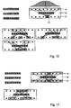
- Figure 10 shows a third schematic view of transmitter / receiver combinations in view of the phased array radar system including a full transmitter array 17 and a full receiver array 18 wherein a transmitter module 71 is defect.
- the lost TR positions are determined.
- the Tr positions are split in 2 equiform parts that fill up each other after applying a shift, see upper left pattern in Fig. 10 .
- the transmitter modules associated with the virtual transceiver modules are mutually orthogonal.
- three taper functions can be applied at the receiver modules associated with the virtual transceiver modules.
- a Tx taper can be incorporated in the left and right half beam taper.
- Figure 11 shows a fourth schematic view of transmitter / receiver combinations in view of the phased array radar system having full receiver and transmitter arrays 18, 17 wherein both a receiver module and a transmitter module are defect.
- a similar strategy can be applied of determining lost TR positions, see upper right pattern, splitting the TR positions in 2 equiform parts that fill up each other after a shift, see upper left pattern, and locating the corresponding Tx array associated with the virtual transceiver module or MIMO, outside the failing module, see lower pattern in Figure 11 .
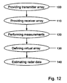
- FIG. 12 shows a flow chart of an embodiment of the method according to the invention.
- a method is used for compensating sub-array or element failure in a phased array radar system.
- the method comprises a step of providing (100) a transmitter array comprising a multiple number of substantially identical transmitter tiles arranged at equidistant positions on a linear transmitting line, a step of providing (110) a receiver array comprising a multiple number of substantially identical receiving tiles arranged at equidistant positions on a linear receiving line, wherein the distance between adjacent transmitting tiles substantially equals the distance between adjacent receiving tiles and wherein the linear transmitting line is substantially parallel to the linear receiving line, a step of performing (120) phased array radar measurements, a step of defining (130) virtual array comprising a multiple number of virtual transceiver tiles arranged halfway all connection lines interconnecting a transmitter tile to a receiver tile, and a step of estimating (140) radar data associated with a first transmitter / receiver combination by using radar data associated with a second transmitter
- the method of compensating sub-array failure in a phased array radar system can be performed using dedicated hardware structures, such as FPGA and/or ASIC components. Otherwise, the method can also at least partially be performed using a computer program product comprising instructions for causing a processor of the computer system to perform the above described steps of the method according to the invention. All processing steps can in principle be performed on a single processor. However it is noted that at least one step can be performed on a separate processor, e.g. the step of estimating radar data associated with a first transmitter / receiver combination by using radar data associated with a second transmitter / receiver combination, having a coinciding transmitter / receiver combination.
- FIG 13 shows a schematic view of a third phased array radar system 1 according to the invention.
- four transmitter tiles t 1-4 are arranged at equidistant positions on a linear transmitting line T line .
- the intermediate distance between subsequent transmitter tiles is distance D t .
- the system 1 further includes four receiver tiles 3 a-d located on a linear receiving line R line .
- the receiver tiles are grouped in two pairs having a mutual offset that is greater than the intermediate distance D r between the tiles in the same pair.
- the intermediate distances Dt and Dr are substantially equal, so that virtual transceiver modules 6 may coincide.
- the intermediate distance between subsequent receivers can be chosen different from the intermediate distance between subsequent transmitters.
- the intermediate distance D r between subsequent receivers can be chosen to be an integer number times greater than the intermediate distance Dt between subsequent transmitters.
- the tiles instead of arranging the transmitters and/or the receivers on a linear line, the tiles can be located on another line, e.g. a curved line. Then, the ratio between intermediate distances of receivers and transmitters, respectively, need not be an integer number.
- a transmission line is substantially parallel to a receiving line.
- the transmission line and the receiving line may intersect at a constant angle. However, in order to apply the invention, at least a number of virtual transmitter tiles coincide.
- the virtual transceiver modules are arranged halfway connection lines interconnecting a transmitter tile to a receiver tile. Then, the system is arranged for imaging radar objects in the so-called far field.
- FIG 14 shows a configuration of a transmitter tile 60, a receiver tile 61 and a corresponding virtual transceiver tile 62.
- the virtual transceiver tile 62 can, more generally, be defined by locating it such that the propagation time of a radar wave transmitted by the transmitter tile 60 and received by the receiver tile 61, via a radar object 70, substantially equals the propagation time of a radar wave transmitted and received by the virtual transceiver tile 62, via the radar object 70.
- the radar wave path length d 1 between the transmitter tile 60 and the radar object 70 added to the radar wave path length d 2 between the radar object 70 and the receiver tile 61 substantially equals two times the radar wave path length d 3 between the virtual transceiver tile 62 and the object 70.
- the radar wave path length may differ from geometrical distances between tiles and radar object.
- the virtual transceiver tile 62 can be located on a sphere S.
- the virtual transceiver tile 62 is e.g. positioned such that the distance between the transmitter and the transceiver is equal to the distance between the receiver and the transceiver, and the distance between the transmitter and the transceiver is minimized.
- the radar object 70 is sufficiently far removed from the transmitter tile 60 and receiver tile 61, the virtual transceiver tile 62 will be located halfway the connection line interconnecting the transmitter 60 and the receiver 61.
- the radar system 1 is arranged for imaging a near field radar object.
Landscapes
- Engineering & Computer Science (AREA)
- Radar, Positioning & Navigation (AREA)
- Remote Sensing (AREA)
- Computer Networks & Wireless Communication (AREA)
- Physics & Mathematics (AREA)
- General Physics & Mathematics (AREA)
- Radar Systems Or Details Thereof (AREA)
Claims (15)
Priority Applications (1)
| Application Number | Priority Date | Filing Date | Title |
|---|---|---|---|
| EP20110708588 EP2545392B1 (fr) | 2010-03-08 | 2011-03-08 | Procédé de compensation d'une défaillance d'élément de sous-réseau dans un système de radar à réseau de phase, système radar à réseau de phase et produit de programme informatique |
Applications Claiming Priority (4)
| Application Number | Priority Date | Filing Date | Title |
|---|---|---|---|
| EP10155774 | 2010-03-08 | ||
| EP10193360A EP2461178A1 (fr) | 2010-12-01 | 2010-12-01 | Procédé de compensation d'une défaillance d'élément de sous-réseau dans un système de radar à réseau de phase, système radar à réseau de phase et produit de programme informatique |
| PCT/NL2011/050161 WO2011112083A1 (fr) | 2010-03-08 | 2011-03-08 | Procédé de compensation de défaillance de sous-réseau ou d'élément dans un système de radar à balayage électronique, système de radar à balayage électronique, et produit-programme d'ordinateur |
| EP20110708588 EP2545392B1 (fr) | 2010-03-08 | 2011-03-08 | Procédé de compensation d'une défaillance d'élément de sous-réseau dans un système de radar à réseau de phase, système radar à réseau de phase et produit de programme informatique |
Publications (2)
| Publication Number | Publication Date |
|---|---|
| EP2545392A1 EP2545392A1 (fr) | 2013-01-16 |
| EP2545392B1 true EP2545392B1 (fr) | 2013-12-25 |
Family
ID=43983954
Family Applications (1)
| Application Number | Title | Priority Date | Filing Date |
|---|---|---|---|
| EP20110708588 Not-in-force EP2545392B1 (fr) | 2010-03-08 | 2011-03-08 | Procédé de compensation d'une défaillance d'élément de sous-réseau dans un système de radar à réseau de phase, système radar à réseau de phase et produit de programme informatique |
Country Status (3)
| Country | Link |
|---|---|
| US (1) | US9140779B2 (fr) |
| EP (1) | EP2545392B1 (fr) |
| WO (1) | WO2011112083A1 (fr) |
Families Citing this family (34)
| Publication number | Priority date | Publication date | Assignee | Title |
|---|---|---|---|---|
| US8570210B1 (en) * | 2011-06-21 | 2013-10-29 | Lockheed Martin Corporation | Aircraft MIMO radar |
| US9019148B1 (en) * | 2012-04-24 | 2015-04-28 | Sandia Corporation | Remote sensing using MIMO systems |
| CN103383450B (zh) * | 2013-06-25 | 2015-05-27 | 西安电子科技大学 | 共形阵列雷达幅相误差校正快速实现方法 |
| JP6492377B2 (ja) * | 2014-08-28 | 2019-04-03 | 日本無線株式会社 | 直交分離装置および直交分離方法 |
| US9882279B2 (en) | 2014-09-24 | 2018-01-30 | Iridium Satellite Llc | Wireless communication terminal |
| JP6453614B2 (ja) * | 2014-11-06 | 2019-01-16 | 株式会社東芝 | Dbfレーダ装置及びそのレーダ信号処理方法 |
| US9791552B1 (en) * | 2014-11-19 | 2017-10-17 | Src, Inc. | On-site calibration of array antenna systems |
| JP6377000B2 (ja) * | 2015-03-25 | 2018-08-22 | パナソニック株式会社 | レーダ装置 |
| KR102422396B1 (ko) * | 2015-09-01 | 2022-07-20 | 주식회사 에이치엘클레무브 | 선형 위상 어레이 안테나의 공간 보간 방법 및 보간 장치 |
| CN105785361B (zh) * | 2016-03-08 | 2018-02-02 | 南京信息工程大学 | 一种阵元失效条件下的mimo雷达成像方法 |
| US10261179B2 (en) | 2016-04-07 | 2019-04-16 | Uhnder, Inc. | Software defined automotive radar |
| WO2017175190A1 (fr) | 2016-04-07 | 2017-10-12 | Uhnder, Inc. | Transmission adaptative et annulation de brouillage pour radar mimo |
| US9846228B2 (en) | 2016-04-07 | 2017-12-19 | Uhnder, Inc. | Software defined automotive radar systems |
| US10573959B2 (en) | 2016-04-25 | 2020-02-25 | Uhnder, Inc. | Vehicle radar system using shaped antenna patterns |
| EP4628936A3 (fr) | 2016-04-25 | 2026-03-11 | Robert Bosch GmbH | Atténuation d'interférences pmcw-pmcw |
| EP3449272B1 (fr) | 2016-04-25 | 2022-11-02 | Uhnder, Inc. | Système radar de véhicule comportant un système radar et de communication partagé, et procédé de gestion d'un tel système au sein d'un véhicule |
| US9791551B1 (en) | 2016-04-25 | 2017-10-17 | Uhnder, Inc. | Vehicular radar system with self-interference cancellation |
| US9945935B2 (en) | 2016-04-25 | 2018-04-17 | Uhnder, Inc. | Digital frequency modulated continuous wave radar using handcrafted constant envelope modulation |
| US9791564B1 (en) | 2016-04-25 | 2017-10-17 | Uhnder, Inc. | Adaptive filtering for FMCW interference mitigation in PMCW radar systems |
| US9753121B1 (en) | 2016-06-20 | 2017-09-05 | Uhnder, Inc. | Power control for improved near-far performance of radar systems |
| WO2018146633A1 (fr) * | 2017-02-10 | 2018-08-16 | Uhnder, Inc. | Génération de code programmable pour systèmes de détection radar |
| US11454697B2 (en) | 2017-02-10 | 2022-09-27 | Uhnder, Inc. | Increasing performance of a receive pipeline of a radar with memory optimization |
| US10908272B2 (en) | 2017-02-10 | 2021-02-02 | Uhnder, Inc. | Reduced complexity FFT-based correlation for automotive radar |
| JP6671312B2 (ja) * | 2017-04-06 | 2020-03-25 | 三菱電機株式会社 | レーダ装置 |
| US11105890B2 (en) | 2017-12-14 | 2021-08-31 | Uhnder, Inc. | Frequency modulated signal cancellation in variable power mode for radar applications |
| US12386029B2 (en) | 2018-01-29 | 2025-08-12 | Robert Bosch Gmbh | Millimeter wave automotive radar systems |
| DE102018203333A1 (de) * | 2018-03-06 | 2019-09-12 | Autocruise S.A.S | Verfahren zur eindeutigen Bestimmung der Geschwindigkeit eines Objekts an einem RADAR Messsystem |
| US11474225B2 (en) | 2018-11-09 | 2022-10-18 | Uhnder, Inc. | Pulse digital mimo radar system |
| DE102019201138A1 (de) * | 2019-01-30 | 2020-07-30 | Zf Friedrichshafen Ag | Sensorsystem zum Detektieren eines Objekts in einer Umgebung eines Fahrzeugs |
| WO2020183392A1 (fr) | 2019-03-12 | 2020-09-17 | Uhnder, Inc. | Procédé et appareil d'atténuation du bruit basse fréquence dans des systèmes radar |
| WO2021144711A2 (fr) | 2020-01-13 | 2021-07-22 | Uhnder, Inc. | Procédé et système de gestion d'intéfrence pour radars numériques |
| US11342973B1 (en) * | 2021-10-19 | 2022-05-24 | King Faisal University | System and method for maintaining link communications in millimeter wave cellular networks |
| US12498452B2 (en) | 2021-12-02 | 2025-12-16 | Robert Bosch Gmbh | Radar system with enhanced processing for increased contrast ratio, improved angular separability and accuracy, and elimination of ghost targets in a single-snapshot |
| US20240396208A1 (en) * | 2023-05-24 | 2024-11-28 | Orbit Communication Systems Ltd. | Aperiodic Monotile Phased Array Antenna and System with No Grating Lobes |
Family Cites Families (13)
| Publication number | Priority date | Publication date | Assignee | Title |
|---|---|---|---|---|
| US4359740A (en) * | 1978-02-06 | 1982-11-16 | Hazeltine Corporation | Phased array antenna with extinguishable phase shifters |
| US5083131A (en) | 1990-05-31 | 1992-01-21 | Hughes Aircraft Company | Local compensation of failed elements of an active antenna array |
| US5416489A (en) * | 1994-03-25 | 1995-05-16 | The United States Of America As Represented By The Secretary Of The Air Force | Substitution procedure and apparatus for phased array error correction |
| SE516142C2 (sv) * | 1999-03-12 | 2001-11-26 | Ericsson Telefon Ab L M | Kompensation av felaktiga element i antenngrupper |
| US6140976A (en) * | 1999-09-07 | 2000-10-31 | Motorola, Inc. | Method and apparatus for mitigating array antenna performance degradation caused by element failure |
| US6573862B2 (en) * | 2000-12-12 | 2003-06-03 | Harris Corporation | Phased array antenna including element control device providing fault detection and related methods |
| US7515939B2 (en) * | 2003-10-01 | 2009-04-07 | Broadcom Corporation | System and method for channel-adaptive antenna selection |
| FR2887036B1 (fr) * | 2005-05-24 | 2007-10-12 | Thales Sa | Procede de formation de faisceau par le calcul, notamment adapte a la compensation de defaillances de modules actifs d'un radar a balayage electronique. |
| FR2894080B1 (fr) | 2005-11-28 | 2009-10-30 | Alcatel Sa | Antenne reseau a maillage irregulier et eventuelle redondance froide |
| PL1989570T3 (pl) | 2006-01-17 | 2017-02-28 | Teledyne Australia Pty Ltd. | Urządzenie i sposób do inwigilacji |
| US8049661B1 (en) * | 2007-11-15 | 2011-11-01 | Lockheed Martin Corporation | Antenna array with robust failed-element processor |
| KR101424280B1 (ko) * | 2008-01-23 | 2014-07-31 | 엘지전자 주식회사 | 다중 입출력 시스템에서, 신호를 송신하는 방법 |
| US8354960B2 (en) * | 2010-04-01 | 2013-01-15 | Massachusetts Institute Of Technology | Method for low sidelobe operation of a phased array antenna having failed antenna elements |
-
2011
- 2011-03-08 EP EP20110708588 patent/EP2545392B1/fr not_active Not-in-force
- 2011-03-08 WO PCT/NL2011/050161 patent/WO2011112083A1/fr not_active Ceased
- 2011-03-08 US US13/581,893 patent/US9140779B2/en not_active Expired - Fee Related
Also Published As
| Publication number | Publication date |
|---|---|
| EP2545392A1 (fr) | 2013-01-16 |
| US20130113652A1 (en) | 2013-05-09 |
| US9140779B2 (en) | 2015-09-22 |
| WO2011112083A1 (fr) | 2011-09-15 |
Similar Documents
| Publication | Publication Date | Title |
|---|---|---|
| EP2545392B1 (fr) | Procédé de compensation d'une défaillance d'élément de sous-réseau dans un système de radar à réseau de phase, système radar à réseau de phase et produit de programme informatique | |
| EP2476163B1 (fr) | Compensation de défaillance d'antenne | |
| US8199048B1 (en) | Calibration technique for phased array antennas | |
| EP2273614B1 (fr) | Procédé et appareil pour le ré-étalonnage du champ d'une antenne de réseau phasé | |
| CN112448746B (zh) | 数模混合波束赋形多通道的校正装置方法及装置 | |
| EP3469745B1 (fr) | Procédé pour étalonner un système d'antenne, dispositif de commande, programme d'ordinateur et produits-programmes d'ordinateur | |
| US20160065323A1 (en) | Coded Imaging and Multi-User Communications Systems | |
| CN111596274A (zh) | 一种圆阵天线实时校准方法 | |
| CN111007504A (zh) | 基于最小冗余的mimo三维成像雷达稀疏阵列设计方法 | |
| EP2461178A1 (fr) | Procédé de compensation d'une défaillance d'élément de sous-réseau dans un système de radar à réseau de phase, système radar à réseau de phase et produit de programme informatique | |
| CN102623804A (zh) | 天线装置及雷达装置 | |
| CN120491087A (zh) | 一种水声成像船载信息处理及显控系统 | |
| KR101739958B1 (ko) | 배열 안테나를 구비하는 레이더 시스템 및 그 운용 방법 | |
| WO2007027814A1 (fr) | Codage dans un système de communication mimo | |
| EP2296223A1 (fr) | Compensation de défaillance d'antenne | |
| CN119095144A (zh) | 一种去中心的分布式节点时频相同步方法 | |
| CN111220951A (zh) | 一种采用互补码抑制旁瓣的目标检测方法 | |
| EP4160252A1 (fr) | Communications radar avec des codes de balayage et de signal fixe | |
| US7846099B2 (en) | Apparatus, system, and method for providing a continuous scanning sequence for ultrasound imaging | |
| KR102316466B1 (ko) | 내부보정을 위한 검사장치, 이를 구비하는 인공위성 합성 개구 레이다, 및 검사방법 | |
| JP2024078789A5 (ja) | レーダ装置、レーダ信号の送信方法、及び、レーダ信号処理装置 | |
| CN119535440A (zh) | 雷达设备和用于运行雷达设备的方法 | |
| US11451314B2 (en) | Measurement method and measurement system | |
| CN118330568B (zh) | 用于多维域编码雷达的解速度模糊方法及装置 | |
| WO2005115250A1 (fr) | Appareil de diagnostic à ultrason |
Legal Events
| Date | Code | Title | Description |
|---|---|---|---|
| PUAI | Public reference made under article 153(3) epc to a published international application that has entered the european phase |
Free format text: ORIGINAL CODE: 0009012 |
|
| 17P | Request for examination filed |
Effective date: 20120924 |
|
| AK | Designated contracting states |
Kind code of ref document: A1 Designated state(s): AL AT BE BG CH CY CZ DE DK EE ES FI FR GB GR HR HU IE IS IT LI LT LU LV MC MK MT NL NO PL PT RO RS SE SI SK SM TR |
|
| DAX | Request for extension of the european patent (deleted) | ||
| GRAP | Despatch of communication of intention to grant a patent |
Free format text: ORIGINAL CODE: EPIDOSNIGR1 |
|
| INTG | Intention to grant announced |
Effective date: 20130731 |
|
| GRAS | Grant fee paid |
Free format text: ORIGINAL CODE: EPIDOSNIGR3 |
|
| GRAA | (expected) grant |
Free format text: ORIGINAL CODE: 0009210 |
|
| AK | Designated contracting states |
Kind code of ref document: B1 Designated state(s): AL AT BE BG CH CY CZ DE DK EE ES FI FR GB GR HR HU IE IS IT LI LT LU LV MC MK MT NL NO PL PT RO RS SE SI SK SM TR |
|
| REG | Reference to a national code |
Ref country code: GB Ref legal event code: FG4D |
|
| REG | Reference to a national code |
Ref country code: CH Ref legal event code: EP |
|
| REG | Reference to a national code |
Ref country code: AT Ref legal event code: REF Ref document number: 646883 Country of ref document: AT Kind code of ref document: T Effective date: 20140115 |
|
| REG | Reference to a national code |
Ref country code: IE Ref legal event code: FG4D |
|
| REG | Reference to a national code |
Ref country code: DE Ref legal event code: R096 Ref document number: 602011004370 Country of ref document: DE Effective date: 20140220 |
|
| REG | Reference to a national code |
Ref country code: NL Ref legal event code: T3 |
|
| PG25 | Lapsed in a contracting state [announced via postgrant information from national office to epo] |
Ref country code: LT Free format text: LAPSE BECAUSE OF FAILURE TO SUBMIT A TRANSLATION OF THE DESCRIPTION OR TO PAY THE FEE WITHIN THE PRESCRIBED TIME-LIMIT Effective date: 20131225 Ref country code: HR Free format text: LAPSE BECAUSE OF FAILURE TO SUBMIT A TRANSLATION OF THE DESCRIPTION OR TO PAY THE FEE WITHIN THE PRESCRIBED TIME-LIMIT Effective date: 20131225 Ref country code: FI Free format text: LAPSE BECAUSE OF FAILURE TO SUBMIT A TRANSLATION OF THE DESCRIPTION OR TO PAY THE FEE WITHIN THE PRESCRIBED TIME-LIMIT Effective date: 20131225 Ref country code: SE Free format text: LAPSE BECAUSE OF FAILURE TO SUBMIT A TRANSLATION OF THE DESCRIPTION OR TO PAY THE FEE WITHIN THE PRESCRIBED TIME-LIMIT Effective date: 20131225 Ref country code: NO Free format text: LAPSE BECAUSE OF FAILURE TO SUBMIT A TRANSLATION OF THE DESCRIPTION OR TO PAY THE FEE WITHIN THE PRESCRIBED TIME-LIMIT Effective date: 20140325 |
|
| REG | Reference to a national code |
Ref country code: AT Ref legal event code: MK05 Ref document number: 646883 Country of ref document: AT Kind code of ref document: T Effective date: 20131225 |
|
| REG | Reference to a national code |
Ref country code: LT Ref legal event code: MG4D |
|
| PG25 | Lapsed in a contracting state [announced via postgrant information from national office to epo] |
Ref country code: LV Free format text: LAPSE BECAUSE OF FAILURE TO SUBMIT A TRANSLATION OF THE DESCRIPTION OR TO PAY THE FEE WITHIN THE PRESCRIBED TIME-LIMIT Effective date: 20131225 Ref country code: RS Free format text: LAPSE BECAUSE OF FAILURE TO SUBMIT A TRANSLATION OF THE DESCRIPTION OR TO PAY THE FEE WITHIN THE PRESCRIBED TIME-LIMIT Effective date: 20131225 |
|
| PG25 | Lapsed in a contracting state [announced via postgrant information from national office to epo] |
Ref country code: EE Free format text: LAPSE BECAUSE OF FAILURE TO SUBMIT A TRANSLATION OF THE DESCRIPTION OR TO PAY THE FEE WITHIN THE PRESCRIBED TIME-LIMIT Effective date: 20131225 Ref country code: BE Free format text: LAPSE BECAUSE OF FAILURE TO SUBMIT A TRANSLATION OF THE DESCRIPTION OR TO PAY THE FEE WITHIN THE PRESCRIBED TIME-LIMIT Effective date: 20131225 Ref country code: IS Free format text: LAPSE BECAUSE OF FAILURE TO SUBMIT A TRANSLATION OF THE DESCRIPTION OR TO PAY THE FEE WITHIN THE PRESCRIBED TIME-LIMIT Effective date: 20140425 |
|
| PG25 | Lapsed in a contracting state [announced via postgrant information from national office to epo] |
Ref country code: RO Free format text: LAPSE BECAUSE OF FAILURE TO SUBMIT A TRANSLATION OF THE DESCRIPTION OR TO PAY THE FEE WITHIN THE PRESCRIBED TIME-LIMIT Effective date: 20131225 Ref country code: AT Free format text: LAPSE BECAUSE OF FAILURE TO SUBMIT A TRANSLATION OF THE DESCRIPTION OR TO PAY THE FEE WITHIN THE PRESCRIBED TIME-LIMIT Effective date: 20131225 Ref country code: SK Free format text: LAPSE BECAUSE OF FAILURE TO SUBMIT A TRANSLATION OF THE DESCRIPTION OR TO PAY THE FEE WITHIN THE PRESCRIBED TIME-LIMIT Effective date: 20131225 Ref country code: CY Free format text: LAPSE BECAUSE OF FAILURE TO SUBMIT A TRANSLATION OF THE DESCRIPTION OR TO PAY THE FEE WITHIN THE PRESCRIBED TIME-LIMIT Effective date: 20131225 Ref country code: CZ Free format text: LAPSE BECAUSE OF FAILURE TO SUBMIT A TRANSLATION OF THE DESCRIPTION OR TO PAY THE FEE WITHIN THE PRESCRIBED TIME-LIMIT Effective date: 20131225 Ref country code: PT Free format text: LAPSE BECAUSE OF FAILURE TO SUBMIT A TRANSLATION OF THE DESCRIPTION OR TO PAY THE FEE WITHIN THE PRESCRIBED TIME-LIMIT Effective date: 20140428 Ref country code: ES Free format text: LAPSE BECAUSE OF FAILURE TO SUBMIT A TRANSLATION OF THE DESCRIPTION OR TO PAY THE FEE WITHIN THE PRESCRIBED TIME-LIMIT Effective date: 20131225 |
|
| REG | Reference to a national code |
Ref country code: DE Ref legal event code: R097 Ref document number: 602011004370 Country of ref document: DE |
|
| PG25 | Lapsed in a contracting state [announced via postgrant information from national office to epo] |
Ref country code: LU Free format text: LAPSE BECAUSE OF FAILURE TO SUBMIT A TRANSLATION OF THE DESCRIPTION OR TO PAY THE FEE WITHIN THE PRESCRIBED TIME-LIMIT Effective date: 20140308 Ref country code: DK Free format text: LAPSE BECAUSE OF FAILURE TO SUBMIT A TRANSLATION OF THE DESCRIPTION OR TO PAY THE FEE WITHIN THE PRESCRIBED TIME-LIMIT Effective date: 20131225 |
|
| PLBE | No opposition filed within time limit |
Free format text: ORIGINAL CODE: 0009261 |
|
| REG | Reference to a national code |
Ref country code: CH Ref legal event code: PL |
|
| STAA | Information on the status of an ep patent application or granted ep patent |
Free format text: STATUS: NO OPPOSITION FILED WITHIN TIME LIMIT |
|
| PG25 | Lapsed in a contracting state [announced via postgrant information from national office to epo] |
Ref country code: PL Free format text: LAPSE BECAUSE OF FAILURE TO SUBMIT A TRANSLATION OF THE DESCRIPTION OR TO PAY THE FEE WITHIN THE PRESCRIBED TIME-LIMIT Effective date: 20131225 |
|
| 26N | No opposition filed |
Effective date: 20140926 |
|
| REG | Reference to a national code |
Ref country code: IE Ref legal event code: MM4A |
|
| REG | Reference to a national code |
Ref country code: DE Ref legal event code: R097 Ref document number: 602011004370 Country of ref document: DE Effective date: 20140926 |
|
| PG25 | Lapsed in a contracting state [announced via postgrant information from national office to epo] |
Ref country code: IE Free format text: LAPSE BECAUSE OF NON-PAYMENT OF DUE FEES Effective date: 20140308 Ref country code: LI Free format text: LAPSE BECAUSE OF NON-PAYMENT OF DUE FEES Effective date: 20140331 Ref country code: CH Free format text: LAPSE BECAUSE OF NON-PAYMENT OF DUE FEES Effective date: 20140331 |
|
| PG25 | Lapsed in a contracting state [announced via postgrant information from national office to epo] |
Ref country code: SI Free format text: LAPSE BECAUSE OF FAILURE TO SUBMIT A TRANSLATION OF THE DESCRIPTION OR TO PAY THE FEE WITHIN THE PRESCRIBED TIME-LIMIT Effective date: 20131225 |
|
| PG25 | Lapsed in a contracting state [announced via postgrant information from national office to epo] |
Ref country code: MT Free format text: LAPSE BECAUSE OF FAILURE TO SUBMIT A TRANSLATION OF THE DESCRIPTION OR TO PAY THE FEE WITHIN THE PRESCRIBED TIME-LIMIT Effective date: 20131225 |
|
| REG | Reference to a national code |
Ref country code: FR Ref legal event code: PLFP Year of fee payment: 6 |
|
| PG25 | Lapsed in a contracting state [announced via postgrant information from national office to epo] |
Ref country code: SM Free format text: LAPSE BECAUSE OF FAILURE TO SUBMIT A TRANSLATION OF THE DESCRIPTION OR TO PAY THE FEE WITHIN THE PRESCRIBED TIME-LIMIT Effective date: 20131225 |
|
| PGFP | Annual fee paid to national office [announced via postgrant information from national office to epo] |
Ref country code: NL Payment date: 20160321 Year of fee payment: 6 |
|
| PG25 | Lapsed in a contracting state [announced via postgrant information from national office to epo] |
Ref country code: MC Free format text: LAPSE BECAUSE OF FAILURE TO SUBMIT A TRANSLATION OF THE DESCRIPTION OR TO PAY THE FEE WITHIN THE PRESCRIBED TIME-LIMIT Effective date: 20131225 |
|
| PGFP | Annual fee paid to national office [announced via postgrant information from national office to epo] |
Ref country code: FR Payment date: 20160321 Year of fee payment: 6 Ref country code: GB Payment date: 20160321 Year of fee payment: 6 |
|
| PG25 | Lapsed in a contracting state [announced via postgrant information from national office to epo] |
Ref country code: BG Free format text: LAPSE BECAUSE OF FAILURE TO SUBMIT A TRANSLATION OF THE DESCRIPTION OR TO PAY THE FEE WITHIN THE PRESCRIBED TIME-LIMIT Effective date: 20131225 Ref country code: IT Free format text: LAPSE BECAUSE OF FAILURE TO SUBMIT A TRANSLATION OF THE DESCRIPTION OR TO PAY THE FEE WITHIN THE PRESCRIBED TIME-LIMIT Effective date: 20131225 Ref country code: GR Free format text: LAPSE BECAUSE OF FAILURE TO SUBMIT A TRANSLATION OF THE DESCRIPTION OR TO PAY THE FEE WITHIN THE PRESCRIBED TIME-LIMIT Effective date: 20140326 |
|
| PG25 | Lapsed in a contracting state [announced via postgrant information from national office to epo] |
Ref country code: TR Free format text: LAPSE BECAUSE OF FAILURE TO SUBMIT A TRANSLATION OF THE DESCRIPTION OR TO PAY THE FEE WITHIN THE PRESCRIBED TIME-LIMIT Effective date: 20131225 Ref country code: HU Free format text: LAPSE BECAUSE OF FAILURE TO SUBMIT A TRANSLATION OF THE DESCRIPTION OR TO PAY THE FEE WITHIN THE PRESCRIBED TIME-LIMIT; INVALID AB INITIO Effective date: 20110308 |
|
| PGFP | Annual fee paid to national office [announced via postgrant information from national office to epo] |
Ref country code: DE Payment date: 20160330 Year of fee payment: 6 |
|
| REG | Reference to a national code |
Ref country code: DE Ref legal event code: R119 Ref document number: 602011004370 Country of ref document: DE |
|
| REG | Reference to a national code |
Ref country code: NL Ref legal event code: MM Effective date: 20170401 |
|
| GBPC | Gb: european patent ceased through non-payment of renewal fee |
Effective date: 20170308 |
|
| REG | Reference to a national code |
Ref country code: FR Ref legal event code: ST Effective date: 20171130 |
|
| PG25 | Lapsed in a contracting state [announced via postgrant information from national office to epo] |
Ref country code: FR Free format text: LAPSE BECAUSE OF NON-PAYMENT OF DUE FEES Effective date: 20170331 Ref country code: DE Free format text: LAPSE BECAUSE OF NON-PAYMENT OF DUE FEES Effective date: 20171003 Ref country code: NL Free format text: LAPSE BECAUSE OF NON-PAYMENT OF DUE FEES Effective date: 20170401 |
|
| PG25 | Lapsed in a contracting state [announced via postgrant information from national office to epo] |
Ref country code: GB Free format text: LAPSE BECAUSE OF NON-PAYMENT OF DUE FEES Effective date: 20170308 |
|
| PG25 | Lapsed in a contracting state [announced via postgrant information from national office to epo] |
Ref country code: MK Free format text: LAPSE BECAUSE OF FAILURE TO SUBMIT A TRANSLATION OF THE DESCRIPTION OR TO PAY THE FEE WITHIN THE PRESCRIBED TIME-LIMIT Effective date: 20131225 |
|
| PG25 | Lapsed in a contracting state [announced via postgrant information from national office to epo] |
Ref country code: AL Free format text: LAPSE BECAUSE OF FAILURE TO SUBMIT A TRANSLATION OF THE DESCRIPTION OR TO PAY THE FEE WITHIN THE PRESCRIBED TIME-LIMIT Effective date: 20131225 |