EP2545767A2 - Wagon à mélanger le fourrage - Google Patents
Wagon à mélanger le fourrage Download PDFInfo
- Publication number
- EP2545767A2 EP2545767A2 EP12005018A EP12005018A EP2545767A2 EP 2545767 A2 EP2545767 A2 EP 2545767A2 EP 12005018 A EP12005018 A EP 12005018A EP 12005018 A EP12005018 A EP 12005018A EP 2545767 A2 EP2545767 A2 EP 2545767A2
- Authority
- EP
- European Patent Office
- Prior art keywords
- feed
- roller
- mixing
- conveyor belt
- feed mixer
- Prior art date
- Legal status (The legal status is an assumption and is not a legal conclusion. Google has not performed a legal analysis and makes no representation as to the accuracy of the status listed.)
- Withdrawn
Links
- 238000002156 mixing Methods 0.000 title claims abstract description 123
- 238000011068 loading method Methods 0.000 claims description 26
- 238000005520 cutting process Methods 0.000 claims description 20
- 235000013305 food Nutrition 0.000 claims description 16
- 238000000034 method Methods 0.000 claims description 11
- 230000008569 process Effects 0.000 claims description 10
- 230000001681 protective effect Effects 0.000 claims description 8
- 150000001875 compounds Chemical class 0.000 claims 1
- 238000002360 preparation method Methods 0.000 claims 1
- 238000003860 storage Methods 0.000 abstract description 8
- 239000000203 mixture Substances 0.000 abstract description 5
- 230000000717 retained effect Effects 0.000 abstract description 2
- 238000011049 filling Methods 0.000 description 9
- 241000208202 Linaceae Species 0.000 description 7
- 235000004431 Linum usitatissimum Nutrition 0.000 description 7
- 238000009825 accumulation Methods 0.000 description 4
- 230000006378 damage Effects 0.000 description 4
- 210000000056 organ Anatomy 0.000 description 4
- 238000005303 weighing Methods 0.000 description 4
- 238000004804 winding Methods 0.000 description 4
- 241000283690 Bos taurus Species 0.000 description 3
- 239000002253 acid Substances 0.000 description 3
- 238000009826 distribution Methods 0.000 description 3
- 230000000694 effects Effects 0.000 description 3
- 230000002349 favourable effect Effects 0.000 description 3
- 244000144972 livestock Species 0.000 description 3
- 239000002245 particle Substances 0.000 description 3
- FERIUCNNQQJTOY-UHFFFAOYSA-N Butyric acid Chemical compound CCCC(O)=O FERIUCNNQQJTOY-UHFFFAOYSA-N 0.000 description 2
- 241001465754 Metazoa Species 0.000 description 2
- 238000005056 compaction Methods 0.000 description 2
- 238000011109 contamination Methods 0.000 description 2
- 238000005260 corrosion Methods 0.000 description 2
- 230000007797 corrosion Effects 0.000 description 2
- 235000021050 feed intake Nutrition 0.000 description 2
- 239000004461 grass silage Substances 0.000 description 2
- 239000008240 homogeneous mixture Substances 0.000 description 2
- 239000000463 material Substances 0.000 description 2
- 238000006748 scratching Methods 0.000 description 2
- 230000002393 scratching effect Effects 0.000 description 2
- 244000025254 Cannabis sativa Species 0.000 description 1
- 241000237858 Gastropoda Species 0.000 description 1
- 240000003483 Leersia hexandra Species 0.000 description 1
- 229910000831 Steel Inorganic materials 0.000 description 1
- 235000006085 Vigna mungo var mungo Nutrition 0.000 description 1
- 240000005616 Vigna mungo var. mungo Species 0.000 description 1
- 238000003916 acid precipitation Methods 0.000 description 1
- 150000007513 acids Chemical class 0.000 description 1
- 230000009471 action Effects 0.000 description 1
- 230000009286 beneficial effect Effects 0.000 description 1
- 230000006835 compression Effects 0.000 description 1
- 238000007906 compression Methods 0.000 description 1
- 239000000470 constituent Substances 0.000 description 1
- 238000010276 construction Methods 0.000 description 1
- 230000008878 coupling Effects 0.000 description 1
- 238000010168 coupling process Methods 0.000 description 1
- 238000005859 coupling reaction Methods 0.000 description 1
- 235000013365 dairy product Nutrition 0.000 description 1
- 238000000151 deposition Methods 0.000 description 1
- 238000007599 discharging Methods 0.000 description 1
- 238000000605 extraction Methods 0.000 description 1
- 238000005429 filling process Methods 0.000 description 1
- 239000010794 food waste Substances 0.000 description 1
- 235000011389 fruit/vegetable juice Nutrition 0.000 description 1
- 230000005484 gravity Effects 0.000 description 1
- 239000004615 ingredient Substances 0.000 description 1
- 230000000977 initiatory effect Effects 0.000 description 1
- 239000004462 maize silage Substances 0.000 description 1
- 238000003801 milling Methods 0.000 description 1
- 230000035515 penetration Effects 0.000 description 1
- 230000002028 premature Effects 0.000 description 1
- 238000003825 pressing Methods 0.000 description 1
- 230000008439 repair process Effects 0.000 description 1
- 230000002441 reversible effect Effects 0.000 description 1
- 238000007665 sagging Methods 0.000 description 1
- 239000004460 silage Substances 0.000 description 1
- 239000010959 steel Substances 0.000 description 1
- 230000007704 transition Effects 0.000 description 1
Images




Classifications
-
- A—HUMAN NECESSITIES
- A01—AGRICULTURE; FORESTRY; ANIMAL HUSBANDRY; HUNTING; TRAPPING; FISHING
- A01K—ANIMAL HUSBANDRY; AVICULTURE; APICULTURE; PISCICULTURE; FISHING; REARING OR BREEDING ANIMALS, NOT OTHERWISE PROVIDED FOR; NEW BREEDS OF ANIMALS
- A01K5/00—Feeding devices for stock or game ; Feeding wagons; Feeding stacks
- A01K5/001—Fodder distributors with mixer or shredder
- A01K5/005—Fodder distributors with mixer or shredder where fodder, e.g. bales, is conveyed by conveyor or slide to mixing or shredding elements on transversal and horizontal axes
Definitions
- the invention relates to a feed mixer for removing, mixing and distributing feed from flax silos according to the preamble of claim 1.
- Feed mixers for livestock feeding, especially for dairy and cattle, are widely known.
- the food often stored in so-called flax silos is taken from these silos, preferably mixed and then presented to the livestock in the form of a feed swath produced with an applicator.
- Some of the mixing systems used to mix the feed components introduced into a mixing chamber of the feed mixer wagon differ considerably.
- mixing systems with horizontal or vertical mixing screws are known.
- systems are known which circulate the feed by means of scratching or Forderb Sn, which are also protected by rotating rollers.
- the feed mixers with horizontal arrangement of the mixing rollers require a high power requirement, as between container walls and mixing screws, especially in the trough-shaped bottom area, feed through strongly compressed, which in addition to high power consumption and associated high energy costs and high wear on mixing screws and container walls leads.
- feed even at low moisture content, it mashes and pampers and is then selected by the animals while eating. The reduced feed content remains and leads partly to noticeable loss of feed.
- a further disadvantage is that the squeezed out food juices, e.g. Acid and butyric acid, lead to acidity and strong Rosterscheinept, which reduces the life of particular containers and mixing screws.
- Food juices e.g. Acid and butyric acid
- Feed mixing wagons with vertical mixing systems have one or more vertically aligned mixing screws within the mixing space. Also in these systems, especially at the bottom of the mixing chamber walls also the risk of crushing of the feed, so that, often after a relatively short period of use, high wear damage may occur because the generally conical, upwardly tapering mixing screws in the lower diameter range with the feed lead high density at the mixing chamber walls along. Too high compression aggressive acids are squeezed out of the feed here, causing the destruction of the container walls is accelerated.
- a further disadvantage is that, especially in the case of more moist silages, feed constituents become entangled and stick together, so that, for example, tennis ball-sized lumps can form during the mixing process and the mixture as a whole is inhomogeneous.
- a homogeneous mixture is a prerequisite for the animals to be fed not selecting the food.
- the aforementioned feed mixers especially those with horizontal augers, have a very high Power requirements and prone to premature wear and associated expensive repairs. They therefore require a heavy and stable construction and have a high energy requirement.
- a feed mixer which has a mixing chamber which can be filled from above and at least two mixing tools arranged in the interior of the mixing chamber.
- the mixing tools are vertically arranged mixing screws, which each cover a working circle projected on the bottom of the mixing chamber (A).
- a passage opening (14) free Guiding arranged by the emergence of dead corners, ie areas where a food mixing is poor or not at all, to be prevented.
- This guide thus represents a special solution for feed mixers with at least two vertical, substantially conical, mixing organs.
- the mixing chamber which are not covered by the rotating mixing organs, problem areas or dead corners.
- it is essentially wedge-shaped wall elements that constrict the mixing chamber in the area between the mixing organs and thereby prevent feed accumulation at these locations.
- the present invention has set itself the goal of creating a feed mixer, which is no longer affected by the mentioned shortcomings of the mixing systems and distributors.
- the food should be easily and wear-resistant mixed, without causing the mixing organs, in particular the mixing roller, to disturbances by, for example, around the roller winding lining ingredients. Also, it should be possible to use the transport volume as much as possible, not only to the lower edge of the mixing roller.
- a feed mixer according to the preamble of claim 1, characterized in that the roller cooperates with a guiding and accumulating device, which is mounted so that in the direction of an end portion of the conveyor conveyor funded feed by means of the guidance and accumulation device of the Roller is retained, whereby the roller can not clog.
- the equipment of a mixing device with a roller and a conveyor belt eliminates the need for more complex mixing screws in terms of their performance requirements and reduces the high power requirement of the mixing device by press-free circulation of the feed by means of the easily drawn conveyor belt.
- the feed is prepared by the distribution effect of the mixing process supporting roller, which also serves to dissolve feed distributions and distribute, to a homogeneous mixture.
- the brought up from the conveyor belt to the roller lining is not forcibly kneaded, but radially accelerated and thrown back into the mixing chamber, where it lays over a wide area on the food already there.
- the mixing process takes place in the form of a cycle:
- the feed is continuously conveyed from the conveyor belt in the direction of the roller.
- the roller dissolves feed particles in larger and smaller portions from the feeding stream supplied to it, or detects the feed coming into its active area and throws it back into the mixing chamber.
- the mixing roller partially enveloping control and storage device prevents that located in the mixing chamber feed, which by the conveyor belt Direction roller is promoted, is pressed against the roller.
- the guide and stowage device prevents the feed from the conveyor belt is pressed against the roller and thus slows down or enforce the roll and optionally arranged on her tools, such as tines, with feed or wind up the feed and the roller as As a result, the food no longer throws into the mixing room, but only rotates in the round.
- the feed mixer is equipped with a loading device, so that the filling of the mixing chamber with an additional machine, such as a tractor with a front loader, unnecessary.
- This charging device may be, for example, a milling device, a cutting blade or a loading shovel. It is essential that the operator of the feed mixer can load the feed independently and independently of another machine.
- the chuck is not only picked up by means of a loading shovel but can also be removed from a flat silo by means of a suitable tool, preferably a cutting shield.
- roller is occupied on its surface with tools.
- tools can also be designed so that they have a crushing effect, so for example, are designed as sharp-edged knives. Clumps possibly present in the feed stream are thus dissolved and the homogeneity of the feed mixture is improved.
- the roller is equipped at its ends with helical spirals whose conveying direction is directed to the center of the hold.
- the food captured in this area by the roller is transported in the direction of the vehicle center.
- the radially accelerated by the centrifugal force feed components receive an additional, to, with respect to the direction of travel, center of the vehicle directed impulse, so that the risk of feed losses is reduced by thrown over the edge of the mixing container or falling feed components during the mixing process.
- the roller is movably mounted within the mixing space, so that the distance between the roller and the conveyor belt can be varied.
- the movable mounting can be realized, for example, by the lateral bearing journals of the roller are taken up by swing arms, which in turn are mounted in the side walls of the mixing chamber.
- a linear movement of the mixing roller is realized by appropriate guide means.
- the distance of the roller to the conveyor belt to the degree of filling of the mixing chamber can be adjusted so that even with smaller mixing rations, the degree of filling not to a fixed roller reached, the fed up by the conveyor to the roller feed detected by the set to a low level roller and then can be thrown back over head into the mixing room to the one to enhance the effect of the roller partially enveloping control and accumulation device, and other only slightly affect the feed intake, it is also beneficial if the control and storage device has an extension below the roller.
- One or more upwardly extending extensions of the guiding and accumulating device can also improve their conveying properties, in particular the release of the feed to be conveyed into the mixing chamber from the roller.
- a cover is provided above the roller, which prevents the accelerated by the roller feed is thrown out of the mixing cart out. Instead, the cover channels the feed stream in the desired conveying direction.
- the protective jacket In order to protect the conveyor belt from damage, it is covered on its underside and on the front side by a protective jacket.
- the protective jacket also prevents food residues, which are not handed over during operation of the conveyor belt in the desired manner to the roller or, when depositing a food swath opposite running conveyor belt to the conveyor belt, fall during the further transport under the mixing truck and contaminate the route ,
- the conveyor belt which is preferably equipped with entrainment strips, conveys the food stored on it in the end region vertically or almost vertically upwards.
- the existing space for the design of the mixing room is used optimally.
- the flow direction of the chuck during the mixing process is positively influenced when the conveyor belt is deflected in the end region by an angle ( ⁇ ) in the direction of the roller.
- the feed flow is thus, after it has first been conveyed largely vertically upwards from the front wall-side region of the conveyor belt, deflected in the direction of the roller to the rear.
- a dispenser which is preferably a cross conveyor
- a front area arranged conveyor belt as in DE 19544231 discloses requires a specially designed front portion of the mixing chamber to ensure that the feed to be applied is placed on the cross conveyor belt.
- arranged in the rear area cross conveyor allows the storage of a over the entire length of the feed passage extending Futterschwades also in stalls that end in a dead-end street and in the feed mixer wagon therefore must be retracted backwards to produce the longest possible feed swath.
- the feed swath does not end at the rear boundary of the house, even in a rear-facing driveway, but rather more.
- the cutting shield In order to cover the transverse conveyor belt during filling and to produce a seal between the transverse conveyor belt and the rear boundary of the mixing chamber, the cutting shield during feeding, it is particularly favorable if the transverse conveyor belt is covered with a pivotable cover flap.
- the cross conveyor is pivoted or retracted in an area below the transport tray and covered in this way.
- the cover flap also bridges an existing between the scraper edge and the top of the conveyor belt height difference and prevents congestion at the transition edge to the conveyor belt arise when the separated from the silo wall feed is transported by swiveling the cutting plate into the mixing chamber.
- the mixing chamber is decoupled from the frame, wherein the coupling points comprise electronic weight sensors.
- the electronic weight sensors may be, for example, weighing pins, which are basically known.
- an electronic control unit preferably a weighing computer
- the weight of a feed mixture which is regularly composed of several different feed components such as grass and maize silage, can be continuously determined. Due to the complete decoupling of the mixing chamber from the frame, it is also possible to continuously determine the weight of the feed located in the mixing chamber during the filling process and to stop the feed supply when a predetermined desired value is reached.
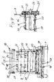
- FIG. 1 An inventive feed mixer is in Fig. 1 shown as a trailer. It essentially comprises the subassemblies chassis 1, mixing chamber 12, mixing device 18, loading device 36 and cross conveyor belt 46 as unloading device. Components of the chassis 1 are the frame 2, the drawbar 3 and the pivoting device 40 with adjustable by means of hydraulic cylinders 5 wings 6 and disposed thereon with the transport wheels. 7
- the mixing chamber 12 is formed from the side walls 8; upwards it is limited in part by the cover 34.
- the rear side 15 is open. It can be closed by a cutting plate 41 depending on the procedure to be performed.
- the underside of the mixing space is bounded by a bottom 13, which merges from an approximately horizontal portion over an arch portion, into an approximately vertical extension, which forms the end wall 14 of the feed mixer wagon.
- the bottom 13 consists of cross members 9, which carry rails 10 arranged thereon with replaceable slide strips 17, wherein the cross member 9 below the side walls 8 arranged guide rails 24 interconnect.
- the mixing device 18 consists essentially of a conveyor belt 19 and the roller 30 partially enveloped by a guide and stowage device 33.
- the guide and stowage device (33) is mounted on a rotation axis (70) while maintaining a minimum distance (x) from the roller (30 ), oscillating stored.
- To set the distance (x) is provided in the figures not shown adjusting member by means of which the control and accumulation device (33) is infinitely variable or adjustable by means of locking adjustable.
- the conveyor belt 19 runs around the bottom 13. It is enclosed on both sides by roller chains 21, which are connected to one another via transverse struts 26 and on which it rests. But it should also not be ruled out that the conveyor belt is guided differently and that find instead of roller chains, for example, profile steel chains or cam profile belt use.
- the cross struts 26 stabilize the leadership of the roller chains 21 and protect in conjunction with the Mitauerangn 20, the conveyor belt 19 against sagging at high payload.
- the rollers 22 of the roller chains 21 extend in guide rails 24, which pass from a horizontal course, by means of the curved path 25, in an approximately vertical course.
- guide rollers 27 At both ends of the guide rails 24 are guide rollers 27, which are equipped on both sides with sprockets 23 for deflecting and driving the roller chains 21 and thus also the conveyor belt 19, respectively.
- cover strips 45 are mounted over the side edges.
- At least one of the guide rollers 27 is provided with a clamping device.
- a hydraulic drive is provided which controls the running speed of the conveyor belt 19 and can switch the direction of flow to return.
- the conveyor belt 19 is shielded downwardly and frontally by a protective jacket 28.
- roller 30 Another component of the mixing device 18, the roller 30, is occupied by tines 31 or other tools, which may be partially equipped with sharp edges for crushing the feed supplied.
- the roller 30 carries on both sides of a helical spiral 29 and 32 with inwardly directed conveying action. In a simpler embodiment, it is also possible to dispense with the helical spirals 29 and 32 and to equip the roller only with tines 31.
- the roller 30 is covered to the mixing chamber 12 and down through the guiding and accumulating device 33.
- the loading device 36 consists of a hydraulic cylinder 37 up and down movable rocker 38, which is mounted with its pivot arms 39 at joints 40 on the frame 2. At the ends of the pivot arms 39 connected via crossbeams 58, there is a cutting plate 41 at the lower edge with knives 42 at the joints 55, via hydraulic cylinders 56 pivotable, attached.
- the rocker 38 can also be equipped in a known manner, for length adjustment, with telescopically executed pivoting arms.
- the loading device 36 is equipped with a known per se Ab Spotifyfräse or a so-called scratching plate instead of the cutting plate 41.
- the cross conveyor belt 46 is mounted in the lower region of the rear side 15 behind the transport floor 19. It is bridged during loading and mixing of a cover plate 47, which is folded up to discharge the feed from a position B 'in a position B, like a bridge.
- the cross conveyor belt 46 consists essentially of the guide rollers 48 carrying frame 49 and the occupied with entrainment 51 conveyor belt 50, which is hydraulically driven and stores food through the discharge openings on the left or right side in a feed passage.
- Fig. 2 it can be seen how, in order to load the feed mixer wagon, the latter is moved up to a flat silo 44 with the loading device raised; by adjusting the pivoting device 4 by means of hydraulic cylinder 5, it is lowered from the transport position T to the working position A, where a scraper edge 57 of a filling threshold 11 is lowered down to the ground and pushed under a flax silo 44.
- the cutting blade 41 is pivoted about the level of a desired, to be separated lining layer thickness D on the flax silo 44.
- the cutting plate 41 When lowering the cutting plate 41 separate the horizontally oscillating at the bottom edge knife 42 and side knife 43 the predetermined feed layer thickness D. from the flax silo 44.
- the separated food is pushed through the open rear side 15 on the filling threshold 11 and cover 47 by pivoting the cutting plate 41 on the conveyor belt 19 and in the mixing chamber 12.
- the conveyor belt 19 conveys the chuck with the support of the entrainment strips 20 in the direction of the end wall 14 and below the roller 30 which is protected against winding and clogging by the guide and stowage device 33 and supports the feed by the conveyor belt 19 leading upwards captured her teeth 31 and throws into the mixing chamber 12.
- the roller 30 takes the material, which falls by gravity or by the conveyor belt 19 on the roller 30, and throws it back into the mixing chamber 12.
- the control and storage device 33 shields the roller against from the mixing chamber 12 in the direction on the roller 30 promoted feed from the mixing chamber 12, which could otherwise block the roller 30 from the mixing chamber side facing.
- a cover 34 is arranged above the roller 30, which is equipped with a pendulum flap or a baffle 35.
- the protective sheath 28 also prevents contamination of the feed passages and feed losses.
- the conveyor belt 19 is deflected in the area of the end wall 14 by an angle ⁇ in the direction of the roller 30.
- the extensions 52 and 53 arranged below and above the guiding and stowing device 33 improve the protection of the roller 30 against clogging and winding.
- the feed mixer For discharging the finished feed mixture, the feed mixer is placed in transport position T ( Fig. 1 ). Thereafter, the cover plate 47 is opened in an approximately vertical position B, partially closes the rear side 14 and thereby releases the cross conveyor belt 46 so that it is fed from the switched to return conveyor belt 19 with feed.
- the food taken over by the cross belt 46 is deposited as required on the right or left side from the moving feed mixer wagon through the outlet openings 54 in a feeding trough.
- FIG. 7 shows another embodiment of the feed mixer according to the invention, which is advantageous for the inclusion of to be mixed, of Siloblockschneider of flax silos Separated feed blocks, made of round or square balers feed bales or from bulk-like feed is suitable.
- a loading shovel 6 is arranged, which is pivotable between a loading position 7 and a transport position H, about the axis of rotation 62 arranged on the chassis 63, via hydraulic cylinders (not shown).
- the convex rear wall 64 forming the rear end of the chassis 63 is adapted to the contour and the pivoting travel of the bucket 60, so that feed losses are prevented over the mixing chamber facing the open side of the bucket 60.
- the rear wall 64 ends above the conveyor belt 65.
- the arrangement of a well-known weighing device requires that mixing chamber 12 and chassis 63 form separate units, which are connected to each other by means of weight sensors 61.
- the loading shovel 60 is assigned to the chassis 63 here.
- the mixing device 68 consisting essentially of the conveyor belt 65 forming the bottom, the conveyor belt 66 arranged vertically about the rotation axis 67, the roller 30 displaceable in guides 69 and the one about the axis of rotation 70 pendelbaren control and storage device 33 consists.
- a cross conveyor belt 46 is arranged at the front of the mixing chamber 12.
- the loading shovel 60 located in the loading position 7 is pushed by resetting the feed mixing carriage under the food to be accommodated. Thereafter, the loading shovel 60 for delivering the feed in pivoted the mixing chamber 12 in the mixing and transport position H.
- the stored on the conveyor belt feed 65 is first moved to create space for further feed intake, forward, since in general several loading operations are necessary for filling.
- the mixing process is initiated by the simultaneous initiation of the conveyor belts 65 and 66 of the roller 30.
- the feed conveyed forward by the conveyor belt 65 pivots the oscillating guide and stowage device 33 up to a minimum distance X, which is ensured by stops, against the roller 30.
- the then captured by the conveyor belt 66 and the roller 30 feed is guided upward and then detected by the roller 30 and thrown into the mixing chamber 12.
- the arranged on the outside of the conveyor belt 66 protective wall 71 avoids that between the conveyor belts 65 and 66 passing and over the conveyor belt 66 entrained feed residues escape from the mixing chamber 12.
- the conveyor belt 66 is pivoted by means of unillustrated hydraulic cylinder from the position K in the position L.
- the conveyor belt 65 leads the food forward.
- the roller 30 may be turned off or, if necessary, revolve at a reduced speed.
- the conveyor belt 66 which is reversed in the reverse direction, captures the chuck and directs it onto the revolving cross conveyor 46, which deposits it through side exit openings 72 on the left or right side of the feed mixer cart in a feed passage.
Landscapes
- Life Sciences & Earth Sciences (AREA)
- Environmental Sciences (AREA)
- Birds (AREA)
- Animal Husbandry (AREA)
- Biodiversity & Conservation Biology (AREA)
- Apparatuses For Bulk Treatment Of Fruits And Vegetables And Apparatuses For Preparing Feeds (AREA)
- Accessories For Mixers (AREA)
- Feeding And Watering For Cattle Raising And Animal Husbandry (AREA)
Applications Claiming Priority (1)
| Application Number | Priority Date | Filing Date | Title |
|---|---|---|---|
| DE201110051833 DE102011051833B3 (de) | 2011-07-14 | 2011-07-14 | Futtermischwagen |
Publications (2)
| Publication Number | Publication Date |
|---|---|
| EP2545767A2 true EP2545767A2 (fr) | 2013-01-16 |
| EP2545767A3 EP2545767A3 (fr) | 2014-04-30 |
Family
ID=46548180
Family Applications (1)
| Application Number | Title | Priority Date | Filing Date |
|---|---|---|---|
| EP12005018.2A Withdrawn EP2545767A3 (fr) | 2011-07-14 | 2012-07-06 | Wagon à mélanger le fourrage |
Country Status (2)
| Country | Link |
|---|---|
| EP (1) | EP2545767A3 (fr) |
| DE (1) | DE102011051833B3 (fr) |
Cited By (2)
| Publication number | Priority date | Publication date | Assignee | Title |
|---|---|---|---|---|
| CN112076674A (zh) * | 2020-09-10 | 2020-12-15 | 广西壮族自治区农业科学院 | 一种改良式撒料车 |
| DE202022106085U1 (de) * | 2022-10-28 | 2024-02-05 | Mayer Verwaltungs Gmbh & Co. Kg | Elektro-hydraulisches Geschwindigkeitsregelsystem |
Families Citing this family (2)
| Publication number | Priority date | Publication date | Assignee | Title |
|---|---|---|---|---|
| CN110622779B (zh) * | 2019-09-24 | 2022-01-18 | 福建嘉田农业开发有限公司 | 锯木屑培养料的制备系统及应用该系统制备培养料的方法 |
| BR132021000489E2 (pt) * | 2021-01-12 | 2022-07-19 | Molin Giovani | Robô móvel multitarefas empregado na distribuição de produtos, insumos e realização de atividades no manejo para criação de animais |
Citations (2)
| Publication number | Priority date | Publication date | Assignee | Title |
|---|---|---|---|---|
| DE19544231A1 (de) | 1995-11-28 | 1997-06-05 | Strautmann & Soehne | Gerät zur Entnahme, zum Mischen und zum Verteilen von Silagefutter aus Flachsilos |
| EP1527678A1 (fr) | 2003-10-16 | 2005-05-04 | Trioliet Mullos B.V. | Mélangeur |
Family Cites Families (6)
| Publication number | Priority date | Publication date | Assignee | Title |
|---|---|---|---|---|
| FR2501130B1 (fr) * | 1981-03-06 | 1986-03-21 | Cacquevel Bernard | Remorque distributrice et melangeuse |
| US4643364A (en) * | 1984-07-20 | 1987-02-17 | Etablissements Lucas G. | Unwinding machine for distributing forage gathered in round bales |
| DE8801587U1 (de) * | 1988-02-09 | 1988-03-31 | Möhrle, Hubert, 7799 Herdwangen-Schönach | Vorrichtung zur Reinigung und Zerkleinerung von Futterrüben |
| NL1001210C1 (nl) * | 1995-05-23 | 1996-11-26 | Schrijver H A M Bv | Transport- en afgiftewagen voor voermateriaal. |
| FR2770370B1 (fr) * | 1997-11-06 | 2004-12-10 | Abc Equip Snc | Desileuse distributrice pour des produits agricoles tels que du fourrage ou les produits emballes dans une balle enrubannee tres compacte |
| NL2000293C2 (nl) * | 2006-03-24 | 2007-09-25 | Cornelis Hendricus Liet | Inrichting voor het doseren van veevoer. |
-
2011
- 2011-07-14 DE DE201110051833 patent/DE102011051833B3/de not_active Expired - Fee Related
-
2012
- 2012-07-06 EP EP12005018.2A patent/EP2545767A3/fr not_active Withdrawn
Patent Citations (2)
| Publication number | Priority date | Publication date | Assignee | Title |
|---|---|---|---|---|
| DE19544231A1 (de) | 1995-11-28 | 1997-06-05 | Strautmann & Soehne | Gerät zur Entnahme, zum Mischen und zum Verteilen von Silagefutter aus Flachsilos |
| EP1527678A1 (fr) | 2003-10-16 | 2005-05-04 | Trioliet Mullos B.V. | Mélangeur |
Cited By (2)
| Publication number | Priority date | Publication date | Assignee | Title |
|---|---|---|---|---|
| CN112076674A (zh) * | 2020-09-10 | 2020-12-15 | 广西壮族自治区农业科学院 | 一种改良式撒料车 |
| DE202022106085U1 (de) * | 2022-10-28 | 2024-02-05 | Mayer Verwaltungs Gmbh & Co. Kg | Elektro-hydraulisches Geschwindigkeitsregelsystem |
Also Published As
| Publication number | Publication date |
|---|---|
| EP2545767A3 (fr) | 2014-04-30 |
| DE102011051833B3 (de) | 2012-09-06 |
Similar Documents
| Publication | Publication Date | Title |
|---|---|---|
| EP1982575B1 (fr) | Presse à empaqueter fonctionnant en continu | |
| EP3078256B1 (fr) | Chariot de recolte comprenant un appareil de dosage et d'epandage | |
| DE69508880T2 (de) | Vorrichtung und Verfahren zum Mischen von Futter | |
| DE102011051833B3 (de) | Futtermischwagen | |
| DE3419997A1 (de) | Futtermischwagen | |
| AT513427B1 (de) | Erntewagen zum Aufnehmen und Transport von Pflanzen oder Pflanzenteilen | |
| DE102011053437B3 (de) | Gerät zur Futterentnahme aus Flachsilos | |
| DE202006006202U1 (de) | Vorrichtung zum Zerkleinern von organischen, verrottungsfähigen Abfallmaterialien | |
| DE2536793C3 (de) | Vorrichtung zum Abtragen, Transportieren und Austeilen von Silagefutter aus Fahrsilos, Mieten o.dgl. (sog.Silofräse) | |
| DE3402959A1 (de) | Elevator | |
| DE102008050562B4 (de) | Ladewagen | |
| DE60301005T2 (de) | Verteilmaschine | |
| DE19510215A1 (de) | Einstreu- und Futterverteilwagen mit Ballenauflösefunktion | |
| DE2218773C3 (de) | Landwirtschaftliches Anhängefahrzeug mit einer Beladevorrichtung | |
| DE19704457A1 (de) | Entladeeinrichtung für landwirtschaftliche Fahrzeuge | |
| AT526069B1 (de) | Vorrichtung zum Ausbringen von einem streufähigen Material | |
| DE3235781A1 (de) | Vorrichtung zur entnahme von massenguetern aus haufen und zur dosierung und/oder zerkleinerung und/oder verteilung bzw. weiterbefoerderung des gutes | |
| AT526320B1 (de) | Vorrichtung zum Ausbringen von einem streufähigen Material | |
| DE3920053C1 (en) | Agricultural silage spreading mechanism - has loading chute at rear and has side delivery rollers and scraper floor | |
| DE19907563C1 (de) | Landwirtschaftliches Fütterungsgerät mit Förderschneckenpaar als Querfördereinrichtung | |
| EP0456213A1 (fr) | Désileuse à rotor pour silo tranchée | |
| DE1205753B (de) | Lade- und Abladewagen fuer landwirtschaftliche Erntegueter, insbesondere langfaserige Erntegueter | |
| DE3935386A1 (de) | Erntemaschine fuer wurzelfruechte, insbesondere zuckerrueben | |
| DE202004010710U1 (de) | Leitvorrichtung für Futter an Futtermischwagen | |
| DE3332010A1 (de) | Vorrichtung zum aufladen von getrocknetem futter |
Legal Events
| Date | Code | Title | Description |
|---|---|---|---|
| PUAI | Public reference made under article 153(3) epc to a published international application that has entered the european phase |
Free format text: ORIGINAL CODE: 0009012 |
|
| AK | Designated contracting states |
Kind code of ref document: A2 Designated state(s): AL AT BE BG CH CY CZ DE DK EE ES FI FR GB GR HR HU IE IS IT LI LT LU LV MC MK MT NL NO PL PT RO RS SE SI SK SM TR |
|
| AX | Request for extension of the european patent |
Extension state: BA ME |
|
| PUAL | Search report despatched |
Free format text: ORIGINAL CODE: 0009013 |
|
| AK | Designated contracting states |
Kind code of ref document: A3 Designated state(s): AL AT BE BG CH CY CZ DE DK EE ES FI FR GB GR HR HU IE IS IT LI LT LU LV MC MK MT NL NO PL PT RO RS SE SI SK SM TR |
|
| AX | Request for extension of the european patent |
Extension state: BA ME |
|
| RIC1 | Information provided on ipc code assigned before grant |
Ipc: A01K 5/00 20060101AFI20140327BHEP |
|
| STAA | Information on the status of an ep patent application or granted ep patent |
Free format text: STATUS: THE APPLICATION IS DEEMED TO BE WITHDRAWN |
|
| 18D | Application deemed to be withdrawn |
Effective date: 20141031 |