EP2545807A2 - Dispositif de rangement et présentoir de chaussures et d'autres objets - Google Patents
Dispositif de rangement et présentoir de chaussures et d'autres objets Download PDFInfo
- Publication number
- EP2545807A2 EP2545807A2 EP12005139A EP12005139A EP2545807A2 EP 2545807 A2 EP2545807 A2 EP 2545807A2 EP 12005139 A EP12005139 A EP 12005139A EP 12005139 A EP12005139 A EP 12005139A EP 2545807 A2 EP2545807 A2 EP 2545807A2
- Authority
- EP
- European Patent Office
- Prior art keywords
- mesh
- arrangement
- shoes
- mesh arrangement
- assembly
- Prior art date
- Legal status (The legal status is an assumption and is not a legal conclusion. Google has not performed a legal analysis and makes no representation as to the accuracy of the status listed.)
- Withdrawn
Links
- 238000003860 storage Methods 0.000 claims abstract description 14
- 238000005286 illumination Methods 0.000 claims 1
- 239000007787 solid Substances 0.000 claims 1
- 125000006850 spacer group Chemical group 0.000 abstract description 14
- 239000000463 material Substances 0.000 description 6
- 238000005096 rolling process Methods 0.000 description 6
- 238000000034 method Methods 0.000 description 5
- 239000000725 suspension Substances 0.000 description 5
- 239000004033 plastic Substances 0.000 description 4
- 229920003023 plastic Polymers 0.000 description 4
- 239000004744 fabric Substances 0.000 description 3
- 229910052751 metal Inorganic materials 0.000 description 3
- 239000002184 metal Substances 0.000 description 3
- 238000010276 construction Methods 0.000 description 2
- 239000000428 dust Substances 0.000 description 2
- 230000002349 favourable effect Effects 0.000 description 2
- 210000002683 foot Anatomy 0.000 description 2
- 244000025254 Cannabis sativa Species 0.000 description 1
- 235000012766 Cannabis sativa ssp. sativa var. sativa Nutrition 0.000 description 1
- 235000012765 Cannabis sativa ssp. sativa var. spontanea Nutrition 0.000 description 1
- 229920000742 Cotton Polymers 0.000 description 1
- 241000196324 Embryophyta Species 0.000 description 1
- 241001295925 Gegenes Species 0.000 description 1
- 229910000831 Steel Inorganic materials 0.000 description 1
- 229910052782 aluminium Inorganic materials 0.000 description 1
- XAGFODPZIPBFFR-UHFFFAOYSA-N aluminium Chemical compound [Al] XAGFODPZIPBFFR-UHFFFAOYSA-N 0.000 description 1
- 230000000712 assembly Effects 0.000 description 1
- 238000000429 assembly Methods 0.000 description 1
- 235000009120 camo Nutrition 0.000 description 1
- 239000011111 cardboard Substances 0.000 description 1
- 235000005607 chanvre indien Nutrition 0.000 description 1
- 238000004140 cleaning Methods 0.000 description 1
- 230000001427 coherent effect Effects 0.000 description 1
- 238000009826 distribution Methods 0.000 description 1
- 230000003670 easy-to-clean Effects 0.000 description 1
- 239000000835 fiber Substances 0.000 description 1
- 230000005484 gravity Effects 0.000 description 1
- 239000011487 hemp Substances 0.000 description 1
- 238000003780 insertion Methods 0.000 description 1
- 230000037431 insertion Effects 0.000 description 1
- 238000009940 knitting Methods 0.000 description 1
- 239000010985 leather Substances 0.000 description 1
- -1 linen Substances 0.000 description 1
- 238000004519 manufacturing process Methods 0.000 description 1
- NJPPVKZQTLUDBO-UHFFFAOYSA-N novaluron Chemical compound C1=C(Cl)C(OC(F)(F)C(OC(F)(F)F)F)=CC=C1NC(=O)NC(=O)C1=C(F)C=CC=C1F NJPPVKZQTLUDBO-UHFFFAOYSA-N 0.000 description 1
- 239000000123 paper Substances 0.000 description 1
- 238000005192 partition Methods 0.000 description 1
- 239000010970 precious metal Substances 0.000 description 1
- 229910000679 solder Inorganic materials 0.000 description 1
- 229910001220 stainless steel Inorganic materials 0.000 description 1
- 239000010935 stainless steel Substances 0.000 description 1
- 239000010959 steel Substances 0.000 description 1
- 210000003371 toe Anatomy 0.000 description 1
- 239000002023 wood Substances 0.000 description 1
Images




Classifications
-
- A—HUMAN NECESSITIES
- A47—FURNITURE; DOMESTIC ARTICLES OR APPLIANCES; COFFEE MILLS; SPICE MILLS; SUCTION CLEANERS IN GENERAL
- A47F—SPECIAL FURNITURE, FITTINGS, OR ACCESSORIES FOR SHOPS, STOREHOUSES, BARS, RESTAURANTS OR THE LIKE; PAYING COUNTERS
- A47F7/00—Show stands, hangers, or shelves, adapted for particular articles or materials
- A47F7/08—Show stands, hangers, or shelves, adapted for particular articles or materials for shoes
-
- A—HUMAN NECESSITIES
- A47—FURNITURE; DOMESTIC ARTICLES OR APPLIANCES; COFFEE MILLS; SPICE MILLS; SUCTION CLEANERS IN GENERAL
- A47B—TABLES; DESKS; OFFICE FURNITURE; CABINETS; DRAWERS; GENERAL DETAILS OF FURNITURE
- A47B61/00—Wardrobes
- A47B61/04—Wardrobes for shoes, hats, umbrellas, or the like
-
- A—HUMAN NECESSITIES
- A47—FURNITURE; DOMESTIC ARTICLES OR APPLIANCES; COFFEE MILLS; SPICE MILLS; SUCTION CLEANERS IN GENERAL
- A47F—SPECIAL FURNITURE, FITTINGS, OR ACCESSORIES FOR SHOPS, STOREHOUSES, BARS, RESTAURANTS OR THE LIKE; PAYING COUNTERS
- A47F5/00—Show stands, hangers, or shelves characterised by their constructional features
- A47F5/08—Show stands, hangers, or shelves characterised by their constructional features secured to the wall, ceiling, or the like; Wall-bracket display devices
- A47F5/0807—Display panels, grids or rods used for suspending merchandise or cards supporting articles; Movable brackets therefor
- A47F5/083—Grids; Article supports therefor
Definitions
- the present invention relates to a device for storing and presenting shoes and accessories.
- the present invention relates to a device for storing and presenting high heel women's shoes.
- the present invention relates to the use of a mesh arrangement, in particular a net, for the storage and presentation of shoes.
- the present invention relates to a kit of parts for producing a device for storing and presenting shoes.
- shoes rack Especially in the private sector, shelves without further shoe-specific features are used. In the commercial sector, these shelves are often expanded by additional structures to present the shoes in an inclined position particularly impressive. For example, behind the shelf raised stacks behind the heels of shoes arranged in the shoe rack and lock them thus in their oblique position.
- Such shoe shelves are not particularly popular in the private sector, for example, only flat men's shoes, but no high boots fit into it and women's shoes with high heels in them are not very stable.
- the space requirements and costs due to the number of parts and the cost of construction are disadvantageous.
- dust and dirt get caught in the shelves, which can not be easily wiped off due to the other support structures.
- the distance between the individual shelves is usually not flexible adjustable. So if more shoes are to be added to the device, the capacity is set a firm limit.
- DE 29 917 890 U1 discloses a hanging rack suspension device in which lattice-shaped parts are arranged perpendicularly or parallel to each other to provide more storage space in wardrobes.
- US 8 151 980 B2 and US 5 261 529 A disclose storage and presentation devices for jewelry such as earrings and brooches, which include planar mesh assemblies in which the jewelry can be placed for mounting.
- An object of the present invention is to provide a space saving device for storing and presenting shoes.
- An object of the present invention is to provide a device for storing and presenting shoes which is easy to clean.
- An object of the present invention is to provide a logistically advantageous device for storing and presenting shoes.
- the present invention achieves the above-mentioned objects by a device having the features according to claim 1, a use according to claim 7 and a parts set having the features according to claim 8.
- a “mesh arrangement” is understood to mean a planar and substantially planar structure which has a plurality of passage openings whose cross-section is large in comparison to the material of the mesh arrangement itself.
- a mesh arrangement in the sense of the present invention can thus be, for example, a net or a grid, wherein the mesh size can be many times greater than the web width of the structure itself.
- a stitch arrangement may in particular be a substantially in-plane arranged plurality of interlocking and / or interconnected loops, e.g. from yarn, ropes, thread, wire or similar.
- the materials of these structures are limited only by the necessity of their ability to absorb certain tensile forces and can e.g. from the amount of wood, cotton, plastics, hemp, linen, metal and steel as well as fibers and braids of the aforementioned materials are selected.
- a mesh arrangement can be produced from the abovementioned materials whose meshes have a low flexibility, so that the mesh width yields only slightly under the influence of tensile forces.
- the stitches can be fixed or, in particular in the case of a net as a mesh arrangement, flexible so that in the first case a stitch is described by respective equal sections of a structure (eg a certain length of yarn), which is ensured, for example, by firm knotting of the fabric is, in the second case interlocking structures are displaced against each other to some extent, as is the case when the structures without a firm anchorage to each other in the manner of a chain link fence have only small angles of wrap with each other.
- a structure eg a certain length of yarn
- the term "substantially flat" is mentioned, one of them is at least partially substantially opposite the sole of a shoe level, global base area or inscribed area of the mesh arrangement understood. A possible local deformation by the introduction of a respective shoe may be disregarded here. In particular, it is advantageous if the widest possible part of the sole has contact with a part of the mesh arrangement, since this stabilizes the seat of the shoe in the mesh arrangement of the device. Also in conjunction with the FIGS. 6 and 7 Embodiments discussed below by way of example therefore disclose substantially planar mesh arrangements in the sense of the invention.
- the present invention provides the opportunity to put through the stitches of the mesh arrangement also accessories and in particular belts, shawls and scarves, so that together can be presented and viewed, which is also used together.
- all parts can be disassembled, transported and stowed in a minimal space, for example the size of a shoebox.
- high heels are understood in the context of the present invention, by which the heel of the foot relative to the ground and towards the toes is raised by a not inconsiderable extent.
- high heels may have a height between the bottom and the shoe sole, which corresponds at least to their diameter, but preferably a multiple, such as a 2-compartment, 3-compartment, 4-compartment or even higher multiples.
- mesh sizes can be used in a wide range.
- mesh sizes in the range between 2 and 10 centimeters have proven effective, in particular between 2 and 4 centimeters, it is possible to introduce almost any women's heel and yet to ensure a high degree of (shape) stability for the entire mesh arrangement. It may also be advantageous to provide different mesh sizes in the mesh arrangement or to provide flexible meshes.
- penny heel to the broad leather belt or even to the winter scarf all possible objects can be arranged in the device.
- a device according to the invention is not limited to the use of a mesh as a mesh arrangement.
- Meshes may also be formed by the appropriate relative arrangement e.g. rod-shaped or pale-shaped structures are created to each other.
- the mesh arrangement can be created by a mesh of flexible rod structures, but also in the manner of a hunter fence, which is known from the garden area, and which consists of an arrangement of two mutually rotated, superimposed arrangements each having substantially parallel bar structures.
- Such a mesh arrangement offers a multitude of creative possibilities, in particular with regard to the materials used.
- a rigid, resilient frame may be further provided for the mesh arrangement.
- the mesh arrangement can be attached and in the case of a network as a mesh arrangement and a necessary bias of the mesh arrangement can be achieved.
- the frame may on the one hand comprise fastening means, on the other hand clamping means.
- the clamping means may comprise, for example, pulleys, pulleys, turnbuckles with clamping screws, eyelets, etc.
- the frame may comprise a profile part in the manner of a guide rail with a lateral (or longitudinal) slot in the form of a groove and / or consist predominantly of such profile parts.
- the stitch assembly may be surrounded by a seam having a greater cross-section than the other stitches of the stitch assembly.
- an outermost row of stitches of the stitching arrangement can also be pulled onto an elongated structure prior to fastening in the profile part, whose cross section, in particular together with a double cross section of the mesh material, is greater than the longitudinal opening of the slot.
- the hem or the elongated structure can be drawn into the profile part through a larger-dimensioned local opening (for example in the end region of the profile parts) and thus the mesh arrangement can be fixed in the profile part.
- spacers may be provided to ensure a predefined distance to the wall on which the device is arranged.
- the spacers may be attached either to the fasteners or to the frame. This ensures that projecting through the mesh arrangement shoe heels and garments do not come into contact with the wall and a secure hold of the shoes is thus guaranteed.
- hinge elements on the fastening means or on the frame, whereby the device can be arranged pivotably.
- the first position is a substantially vertical position as described above for the presentation and selection of shoes, a second position, in particular for space-saving storage of shoes, which is less for presentation and selection of shoes.
- the hinge elements can enable pivoting of the frame from a vertical to a substantially horizontal orientation of the device.
- rolling elements and / or sliding elements can be provided on the frame of the device.
- the device can be pulled out, for example, in the horizontal direction, for example, behind a cabinet and pushed back there after the selection of shoes.
- space can be saved in that the selection process, which requires only little time, takes place, for example, in front of a door or in a passage area of a room, which is released again after the selection process by moving it again.
- the device for selecting garments can also be pushed into an area in which favorable lighting conditions (eg daylight) prevail, but after the selection process, the device is pushed back into an area in which the shoes are protected on the one hand from light, on the other hand from dust .
- a rail arranged on the floor or on the ceiling can be provided, which also has the rolling elements and / or sliding elements as an alternative.
- wall-mounted rails may be used in which the frame of the device is mounted rollingly or slidably.
- a profile part is used as the frame, it can preferably also have a groove on its side opposite the mesh arrangement, in which suspension and / or sliding and / or rolling elements can be arranged in order to bring them into engagement with a guide rail fixed on the room side ,
- a pulling device may be provided in the mesh arrangement which, for example, a sling, in particular with a arranged on the back of the mesh arrangement traction means
- a mass element ausgestaltet- includes.
- the pulling device can be designed for a single shoe or several shoes, in particular a pair of shoes, such that with a handle the pulling device can be pulled and / or dabbed by a user at the front of the stitch arrangement and with a second handle a shoe with the Leading edge of his paragraph can be arranged on the structural element. Now, if the traction device is released by the user, the shoe is pulled through the intermediary of the traction means of the pulling device in the direction of the mesh arrangement and slipping of the heel of the structural element is prevented in a simple manner.
- the device according to the invention may comprise a second mesh arrangement, which is arranged substantially parallel and at a distance of a few centimeters behind the first, previously discussed mesh arrangement.
- the second mesh arrangement can be arranged between the space boundary and the first mesh arrangement, preferably at a distance of approximately 3 to 6 centimeters from the first mesh arrangement.
- the first and second stitching arrangements are to be arranged and shoes inserted into the apparatus such that the heels in the apparatus arranged on the shoes can rest on a stitch boundary of the first stitch arrangement, while a stitch restriction of the second stitch arrangement depresses the heel.
- the device clamps the heel of the shoe between the first and the second stitching arrangement, whereby a higher frictional force is created and unwanted falling out of shoes from the device is even more reliably prevented.
- the ground-level area of heels which is often formed by a replaceable plastic insert, provides a slight opportunity for undercut by mesh limitations of the second mesh arrangement by slight cross-sectional enlargements.
- the device may comprise lighting means for illuminating the shoes and accessories arranged in it. These can either be mounted in the frame or separately in the area of the device at a room boundary. For example, individual LED spots could specifically highlight favorite shoes.
- the present invention relates to the use of a substantially vertical stitching arrangement for storing and presenting shoes.
- the use may take the form of a device discussed above.
- flat mesh arrangements for storage and presentation of shoes have been found to be advantageous, but also cylindrical or frusto-conical mesh arrangements are also possible.
- a kit of parts for making a shoe storage and presentation device includes a substantially vertically alsspannbare mesh arrangement and / or elements for producing a substantially vertical mesh arrangement.
- This may be, for example, a net, a grid, as well as a framework or other element or other elements.
- the kit of parts can comprise fastening means for fixing the mesh arrangement in a substantially vertically clamped state in building interiors. In the simplest case, these can be a suitable number of screw hooks.
- the kit of parts may also include spacers, in particular on the attachment means, by means of which the mesh arrangement obtains a predefined distance from the wall to which the device is attached.
- the spacers which can be screwed in a wall comprise a region projecting from the wall, at the outer end of which a hook element or the like makes it possible to fasten the mesh arrangement.
- the parts set can have components for creating a frame on which the mesh arrangement can be applied.
- a rectangular frame shape is only one possible, but not the only conceivable frame shape.
- a framework does not necessarily mean a coherent structure. As will be shown in connection with the figures, a large number of design options are also available in connection with several, in particular round, frame elements.
- holding elements can be provided in the device or in the parts set, wherein first means allow attachment of the holding element in the mesh arrangement of the device, second means for fastening garments are provided on the holding element itself.
- first and second fastening means may comprise hooks and / or clamping elements to which shoes with improper heels and scarves and other accessories may be placed.
- the present invention is not limited in its application to a particular heel shape of women's shoes, but can find almost unlimited use for storing shoes, accessories, garments and other items.
- the device according to the invention is of course not on the attachment to fixed (im Meaning of permanent) limited space and can for example be arranged in pieces of furniture. For example, it can also be arranged inside a (clothing) cabinet, or on a mobile partition wall.
- One in the FIGS. 13, 14 and 15 shown frame variant consists of profile parts 20, which are designed as guide rails.
- the profile parts 20 -as in connection with the FIGS. 11 and 12 executed at least one slot as a groove 21 along a longitudinal side.
- Two pairs of parallel guide rails can be cut at the corners, which can be cut to a 45 ° miter, in particular for a right-angled arrangement, are fixed together by connectors 23, the first end 24 is inserted into a front-side first cavity of a first profile part 20 and the second end 24 is inserted into a front-side second cavity of an adjacent second profile part 20. Between the first and the second end 24 of the connector 23, this has a holding portion 25 to which a mesh arrangement 2 can be attached.
- a clamping means may be arranged, for example in the manner of a turnbuckle 30 with clamping screws 31, by means of which the stitch assembly 2 can be stretched in the frame defined by the profile parts 20.
- Such an arrangement is in each case for the four corners of the mesh arrangement 2 in FIG Fig. 15 shown.
- the connectors 23 are pressed into the frontal cavities of the profile parts 20, which is why a screwing of the ends can be omitted.
- further holding devices can be arranged in the grooves 21 of the profile parts 20, in particular displaceably, in order to also fix and / or clamp side areas of the mesh arrangement 2.
- Such a holder of the mesh arrangement 2 can, as in Fig. 14 represented, of course, be combined with an introduction of a Kettelung the mesh assembly 2 in the grooves 21 of the profile parts 20. In this way, the profile parts 20 deforming forces and moments can be distributed in a suitable manner.
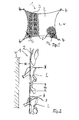
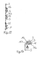
- Fig. 16 shows a detailed view of a structural element 27 which is hooked into a mesh arrangement 2.
- a structural member 27 At an upper portion of the structural member 27 is disposed a horizontal portion 29 for supporting a front flank of a heel of a men's shoe.
- the mesh assembly 20 opposite side is provided a vertically protruding from the plane of the horizontal portion 29 edge 29a, which causes an improved frictional engagement, depending on the geometry of a positive connection with the heel of the men's shoe.
- a cable loop as a pulling device 26 is guided from the front side of the stitch assembly 2 by two adjacent stitches 3, so that the ends of the rope hang down at the back of the stitch assembly 2.
- a sleeve 28 are mounted on the loop for each shoe. The sleeves 28 ensure an improved fit with the shoes.
- Fig. 17 shows a side view of a structural element 27 with a arranged on this, fixed by a pulling device 26 shoe.
- a mass element m is provided as a tension element, via which a tensile force is exerted on the shoe for securing the same.
- Fig. 18 shows a side view of an arrangement of a less suitable ladies shoe L in a device 1 according to the invention, in which the ladies shoe L is secured by means of a pulling device 26 against a release of the engagement of his heel H with a stitch 3 of the stitch assembly 2, without a structural element 27 would be required.
- the invention is based on the finding that a predominant percentage of women's shoes have proportions in shape and mass distribution, which at least allows very reliable and fast hooking such shoes with their heel in a mesh arrangement, if the sole of the shoe at least not substantially the (imaginary ) "Breaks through” the solder through the point of contact between the stitch arrangement and the heel of the shoe (see also Fig. 2 ).
- the sole of the shoe at least not substantially the (imaginary ) "Breaks through” the solder through the point of contact between the stitch arrangement and the heel of the shoe (see also Fig. 2 ).
- the core idea of the present invention is to combine a large quantity of shoes, especially high-heeled women's shoes, in a most compact constellation such that the tops of the shoes can be arranged close to one another and thus examined and selected. Since a very large amount of space would be the result of an arrangement on the floor, the invention proposes to store the shoes substantially vertically one above the other, while maintaining the above relative arrangement of the shoes to each other while the high heels of the shoes to anchor the shoes in to use the device.
- the invention therefore proposes a stitch arrangement, wherein the apparatus is set up, preferably to produce a minimum predefined distance of the stitch arrangement from a space boundary, before which it can be arranged.
- the predefined distance may be at least 2 cm, but preferably between about 8 cm and 15 cm, most preferably 10 cm.
Landscapes
- Footwear And Its Accessory, Manufacturing Method And Apparatuses (AREA)
- Holders For Apparel And Elements Relating To Apparel (AREA)
Applications Claiming Priority (1)
| Application Number | Priority Date | Filing Date | Title |
|---|---|---|---|
| DE102011107156.7A DE102011107156B4 (de) | 2011-07-14 | 2011-07-14 | Vorrichtung zur Aufbewahrung und Präsentation von Schuhen und anderen Gegenständen |
Publications (2)
| Publication Number | Publication Date |
|---|---|
| EP2545807A2 true EP2545807A2 (fr) | 2013-01-16 |
| EP2545807A3 EP2545807A3 (fr) | 2014-10-29 |
Family
ID=46582510
Family Applications (1)
| Application Number | Title | Priority Date | Filing Date |
|---|---|---|---|
| EP12005139.6A Withdrawn EP2545807A3 (fr) | 2011-07-14 | 2012-07-12 | Dispositif de rangement et présentoir de chaussures et d'autres objets |
Country Status (2)
| Country | Link |
|---|---|
| EP (1) | EP2545807A3 (fr) |
| DE (1) | DE102011107156B4 (fr) |
Cited By (2)
| Publication number | Priority date | Publication date | Assignee | Title |
|---|---|---|---|---|
| ES2531175A1 (es) * | 2013-09-10 | 2015-03-11 | Sentis Eloy Ferre | Malla expositora componible |
| US20180249829A1 (en) * | 2017-03-03 | 2018-09-06 | Daniel A. Gilmour | Shoe rack and shoe rack kit |
Citations (4)
| Publication number | Priority date | Publication date | Assignee | Title |
|---|---|---|---|---|
| DE8425039U1 (de) | 1984-08-24 | 1984-11-15 | Verkerke Reproduktionen Handelsgesellschaft mbH, 4230 Wesel | Staender zur praesentation von verkaufsguetern o. dgl. |
| US5261529A (en) | 1992-07-10 | 1993-11-16 | Holland Joanne P | Earring storage and display apparatus and method |
| DE29917890U1 (de) | 1999-10-11 | 2000-02-03 | Veith, Rudolf, 42549 Velbert | Aufhängvorrichtung für Hängeregale |
| US8151980B2 (en) | 2009-07-14 | 2012-04-10 | Demartino Susan | Jewelry holder and organizer |
-
2011
- 2011-07-14 DE DE102011107156.7A patent/DE102011107156B4/de not_active Expired - Fee Related
-
2012
- 2012-07-12 EP EP12005139.6A patent/EP2545807A3/fr not_active Withdrawn
Patent Citations (4)
| Publication number | Priority date | Publication date | Assignee | Title |
|---|---|---|---|---|
| DE8425039U1 (de) | 1984-08-24 | 1984-11-15 | Verkerke Reproduktionen Handelsgesellschaft mbH, 4230 Wesel | Staender zur praesentation von verkaufsguetern o. dgl. |
| US5261529A (en) | 1992-07-10 | 1993-11-16 | Holland Joanne P | Earring storage and display apparatus and method |
| DE29917890U1 (de) | 1999-10-11 | 2000-02-03 | Veith, Rudolf, 42549 Velbert | Aufhängvorrichtung für Hängeregale |
| US8151980B2 (en) | 2009-07-14 | 2012-04-10 | Demartino Susan | Jewelry holder and organizer |
Cited By (2)
| Publication number | Priority date | Publication date | Assignee | Title |
|---|---|---|---|---|
| ES2531175A1 (es) * | 2013-09-10 | 2015-03-11 | Sentis Eloy Ferre | Malla expositora componible |
| US20180249829A1 (en) * | 2017-03-03 | 2018-09-06 | Daniel A. Gilmour | Shoe rack and shoe rack kit |
Also Published As
| Publication number | Publication date |
|---|---|
| DE102011107156A1 (de) | 2013-01-17 |
| DE102011107156B4 (de) | 2020-09-03 |
| EP2545807A3 (fr) | 2014-10-29 |
Similar Documents
| Publication | Publication Date | Title |
|---|---|---|
| DE602004008449T2 (de) | System zum anbringen von zubehör an einem regal | |
| DE2758290A1 (de) | Sportgeraet | |
| EP3945950A1 (fr) | Planche à bijoux | |
| EP2545807A2 (fr) | Dispositif de rangement et présentoir de chaussures et d'autres objets | |
| DE202015102950U1 (de) | Vorrichtung zum Anbau von Pflanzen und Kräutern | |
| EP1092365A1 (fr) | Meuble | |
| DE19923257A1 (de) | Variables Scherengittergestell | |
| DE1429655A1 (de) | Warenausstellungsschrank | |
| DE19944232C2 (de) | Anordnung für den Einbau in einen Schrank | |
| DE202019102065U1 (de) | Drehsäulenmöbel | |
| DE2004466C (de) | Vorrichtung zur Halterung von bandar tigen Gegenstanden | |
| AT340632B (de) | Regalmobel | |
| DE3320493C2 (de) | Ladenregal | |
| DE202022105845U1 (de) | Vorrichtung zum Stabilisieren eines Stiefelschafts und Gestell zur Lagerung dieser Vorrichtung | |
| DE19758236C1 (de) | Raumtragwerk | |
| DE9105078U1 (de) | Präsentationsregal für Mustertafeln | |
| DE2120050C3 (de) | Vorrichtung zum Ausstellen von Teppichmustern | |
| DE102016110749B4 (de) | Verbesserte Vorrichtung zum Aufhängen von Kleiderstücken | |
| DE202012000455U1 (de) | Regalmöbel aus gewickelter Pappe | |
| DE9108404U1 (de) | Päsentations- und Verkaufsetage, insbesondere für Geschenkbandrollen | |
| DE10315722A1 (de) | Schirmwand | |
| DE202013100077U1 (de) | Kleiderhaken zur losen Anbringung an einem Regalbrett | |
| DE202014105487U1 (de) | Selbststehende Verkaufshilfe | |
| DE202011004225U1 (de) | Präsentationsvorrichtung für Geschenke, Waren, Schmuckgegenstände o. dgl. | |
| DE102012000879A1 (de) | Regalmöbel aus gewickelter Pappe |
Legal Events
| Date | Code | Title | Description |
|---|---|---|---|
| PUAI | Public reference made under article 153(3) epc to a published international application that has entered the european phase |
Free format text: ORIGINAL CODE: 0009012 |
|
| AK | Designated contracting states |
Kind code of ref document: A2 Designated state(s): AL AT BE BG CH CY CZ DE DK EE ES FI FR GB GR HR HU IE IS IT LI LT LU LV MC MK MT NL NO PL PT RO RS SE SI SK SM TR |
|
| AX | Request for extension of the european patent |
Extension state: BA ME |
|
| PUAL | Search report despatched |
Free format text: ORIGINAL CODE: 0009013 |
|
| AK | Designated contracting states |
Kind code of ref document: A3 Designated state(s): AL AT BE BG CH CY CZ DE DK EE ES FI FR GB GR HR HU IE IS IT LI LT LU LV MC MK MT NL NO PL PT RO RS SE SI SK SM TR |
|
| AX | Request for extension of the european patent |
Extension state: BA ME |
|
| RIC1 | Information provided on ipc code assigned before grant |
Ipc: A47F 7/08 20060101ALI20140922BHEP Ipc: A47B 61/04 20060101AFI20140922BHEP |
|
| STAA | Information on the status of an ep patent application or granted ep patent |
Free format text: STATUS: THE APPLICATION IS DEEMED TO BE WITHDRAWN |
|
| 18D | Application deemed to be withdrawn |
Effective date: 20150203 |