EP2546045A1 - Dispositif et procédé de soutien de profilés de matières synthétique dans des lignes d'extrusion - Google Patents
Dispositif et procédé de soutien de profilés de matières synthétique dans des lignes d'extrusion Download PDFInfo
- Publication number
- EP2546045A1 EP2546045A1 EP12176362A EP12176362A EP2546045A1 EP 2546045 A1 EP2546045 A1 EP 2546045A1 EP 12176362 A EP12176362 A EP 12176362A EP 12176362 A EP12176362 A EP 12176362A EP 2546045 A1 EP2546045 A1 EP 2546045A1
- Authority
- EP
- European Patent Office
- Prior art keywords
- support
- plastic profiles
- supporting
- support elements
- supporting plastic
- Prior art date
- Legal status (The legal status is an assumption and is not a legal conclusion. Google has not performed a legal analysis and makes no representation as to the accuracy of the status listed.)
- Withdrawn
Links
- 239000004033 plastic Substances 0.000 title claims abstract description 46
- 238000001125 extrusion Methods 0.000 title claims abstract description 28
- 238000000034 method Methods 0.000 title claims abstract description 7
- 238000001816 cooling Methods 0.000 claims description 15
- 239000003000 extruded plastic Substances 0.000 claims description 5
- 238000007373 indentation Methods 0.000 claims description 3
- 238000004519 manufacturing process Methods 0.000 description 2
- 239000000463 material Substances 0.000 description 2
- 239000000843 powder Substances 0.000 description 2
- 238000007665 sagging Methods 0.000 description 2
- XLYOFNOQVPJJNP-UHFFFAOYSA-N water Substances O XLYOFNOQVPJJNP-UHFFFAOYSA-N 0.000 description 2
- 230000001419 dependent effect Effects 0.000 description 1
- 230000000694 effects Effects 0.000 description 1
- 239000008187 granular material Substances 0.000 description 1
- 238000009420 retrofitting Methods 0.000 description 1
- 239000007921 spray Substances 0.000 description 1
- 230000035900 sweating Effects 0.000 description 1
- 229920005992 thermoplastic resin Polymers 0.000 description 1
Images



Classifications
-
- B—PERFORMING OPERATIONS; TRANSPORTING
- B65—CONVEYING; PACKING; STORING; HANDLING THIN OR FILAMENTARY MATERIAL
- B65G—TRANSPORT OR STORAGE DEVICES, e.g. CONVEYORS FOR LOADING OR TIPPING, SHOP CONVEYOR SYSTEMS OR PNEUMATIC TUBE CONVEYORS
- B65G13/00—Roller-ways
- B65G13/11—Roller frames
- B65G13/12—Roller frames adjustable
-
- B—PERFORMING OPERATIONS; TRANSPORTING
- B29—WORKING OF PLASTICS; WORKING OF SUBSTANCES IN A PLASTIC STATE IN GENERAL
- B29C—SHAPING OR JOINING OF PLASTICS; SHAPING OF MATERIAL IN A PLASTIC STATE, NOT OTHERWISE PROVIDED FOR; AFTER-TREATMENT OF THE SHAPED PRODUCTS, e.g. REPAIRING
- B29C48/00—Extrusion moulding, i.e. expressing the moulding material through a die or nozzle which imparts the desired form; Apparatus therefor
- B29C48/03—Extrusion moulding, i.e. expressing the moulding material through a die or nozzle which imparts the desired form; Apparatus therefor characterised by the shape of the extruded material at extrusion
- B29C48/09—Articles with cross-sections having partially or fully enclosed cavities, e.g. pipes or channels
-
- B—PERFORMING OPERATIONS; TRANSPORTING
- B29—WORKING OF PLASTICS; WORKING OF SUBSTANCES IN A PLASTIC STATE IN GENERAL
- B29C—SHAPING OR JOINING OF PLASTICS; SHAPING OF MATERIAL IN A PLASTIC STATE, NOT OTHERWISE PROVIDED FOR; AFTER-TREATMENT OF THE SHAPED PRODUCTS, e.g. REPAIRING
- B29C48/00—Extrusion moulding, i.e. expressing the moulding material through a die or nozzle which imparts the desired form; Apparatus therefor
- B29C48/25—Component parts, details or accessories; Auxiliary operations
- B29C48/355—Conveyors for extruded articles
-
- B—PERFORMING OPERATIONS; TRANSPORTING
- B29—WORKING OF PLASTICS; WORKING OF SUBSTANCES IN A PLASTIC STATE IN GENERAL
- B29C—SHAPING OR JOINING OF PLASTICS; SHAPING OF MATERIAL IN A PLASTIC STATE, NOT OTHERWISE PROVIDED FOR; AFTER-TREATMENT OF THE SHAPED PRODUCTS, e.g. REPAIRING
- B29C48/00—Extrusion moulding, i.e. expressing the moulding material through a die or nozzle which imparts the desired form; Apparatus therefor
- B29C48/25—Component parts, details or accessories; Auxiliary operations
- B29C48/88—Thermal treatment of the stream of extruded material, e.g. cooling
- B29C48/90—Thermal treatment of the stream of extruded material, e.g. cooling with calibration or sizing, i.e. combined with fixing or setting of the final dimensions of the extruded article
- B29C48/901—Thermal treatment of the stream of extruded material, e.g. cooling with calibration or sizing, i.e. combined with fixing or setting of the final dimensions of the extruded article of hollow bodies
- B29C48/903—Thermal treatment of the stream of extruded material, e.g. cooling with calibration or sizing, i.e. combined with fixing or setting of the final dimensions of the extruded article of hollow bodies externally
-
- B—PERFORMING OPERATIONS; TRANSPORTING
- B29—WORKING OF PLASTICS; WORKING OF SUBSTANCES IN A PLASTIC STATE IN GENERAL
- B29C—SHAPING OR JOINING OF PLASTICS; SHAPING OF MATERIAL IN A PLASTIC STATE, NOT OTHERWISE PROVIDED FOR; AFTER-TREATMENT OF THE SHAPED PRODUCTS, e.g. REPAIRING
- B29C48/00—Extrusion moulding, i.e. expressing the moulding material through a die or nozzle which imparts the desired form; Apparatus therefor
- B29C48/25—Component parts, details or accessories; Auxiliary operations
- B29C48/88—Thermal treatment of the stream of extruded material, e.g. cooling
- B29C48/90—Thermal treatment of the stream of extruded material, e.g. cooling with calibration or sizing, i.e. combined with fixing or setting of the final dimensions of the extruded article
- B29C48/906—Thermal treatment of the stream of extruded material, e.g. cooling with calibration or sizing, i.e. combined with fixing or setting of the final dimensions of the extruded article using roller calibration
-
- B—PERFORMING OPERATIONS; TRANSPORTING
- B29—WORKING OF PLASTICS; WORKING OF SUBSTANCES IN A PLASTIC STATE IN GENERAL
- B29C—SHAPING OR JOINING OF PLASTICS; SHAPING OF MATERIAL IN A PLASTIC STATE, NOT OTHERWISE PROVIDED FOR; AFTER-TREATMENT OF THE SHAPED PRODUCTS, e.g. REPAIRING
- B29C48/00—Extrusion moulding, i.e. expressing the moulding material through a die or nozzle which imparts the desired form; Apparatus therefor
- B29C48/25—Component parts, details or accessories; Auxiliary operations
- B29C48/88—Thermal treatment of the stream of extruded material, e.g. cooling
- B29C48/90—Thermal treatment of the stream of extruded material, e.g. cooling with calibration or sizing, i.e. combined with fixing or setting of the final dimensions of the extruded article
- B29C48/907—Thermal treatment of the stream of extruded material, e.g. cooling with calibration or sizing, i.e. combined with fixing or setting of the final dimensions of the extruded article using adjustable calibrators, e.g. the dimensions of the calibrator being changeable
-
- B—PERFORMING OPERATIONS; TRANSPORTING
- B29—WORKING OF PLASTICS; WORKING OF SUBSTANCES IN A PLASTIC STATE IN GENERAL
- B29C—SHAPING OR JOINING OF PLASTICS; SHAPING OF MATERIAL IN A PLASTIC STATE, NOT OTHERWISE PROVIDED FOR; AFTER-TREATMENT OF THE SHAPED PRODUCTS, e.g. REPAIRING
- B29C48/00—Extrusion moulding, i.e. expressing the moulding material through a die or nozzle which imparts the desired form; Apparatus therefor
- B29C48/25—Component parts, details or accessories; Auxiliary operations
- B29C48/265—Support structures or bases for apparatus, e.g. frames
-
- B—PERFORMING OPERATIONS; TRANSPORTING
- B29—WORKING OF PLASTICS; WORKING OF SUBSTANCES IN A PLASTIC STATE IN GENERAL
- B29C—SHAPING OR JOINING OF PLASTICS; SHAPING OF MATERIAL IN A PLASTIC STATE, NOT OTHERWISE PROVIDED FOR; AFTER-TREATMENT OF THE SHAPED PRODUCTS, e.g. REPAIRING
- B29C48/00—Extrusion moulding, i.e. expressing the moulding material through a die or nozzle which imparts the desired form; Apparatus therefor
- B29C48/25—Component parts, details or accessories; Auxiliary operations
- B29C48/88—Thermal treatment of the stream of extruded material, e.g. cooling
- B29C48/885—External treatment, e.g. by using air rings for cooling tubular films
-
- B—PERFORMING OPERATIONS; TRANSPORTING
- B29—WORKING OF PLASTICS; WORKING OF SUBSTANCES IN A PLASTIC STATE IN GENERAL
- B29C—SHAPING OR JOINING OF PLASTICS; SHAPING OF MATERIAL IN A PLASTIC STATE, NOT OTHERWISE PROVIDED FOR; AFTER-TREATMENT OF THE SHAPED PRODUCTS, e.g. REPAIRING
- B29C48/00—Extrusion moulding, i.e. expressing the moulding material through a die or nozzle which imparts the desired form; Apparatus therefor
- B29C48/25—Component parts, details or accessories; Auxiliary operations
- B29C48/88—Thermal treatment of the stream of extruded material, e.g. cooling
- B29C48/90—Thermal treatment of the stream of extruded material, e.g. cooling with calibration or sizing, i.e. combined with fixing or setting of the final dimensions of the extruded article
- B29C48/905—Thermal treatment of the stream of extruded material, e.g. cooling with calibration or sizing, i.e. combined with fixing or setting of the final dimensions of the extruded article using wet calibration, i.e. in a quenching tank
-
- B—PERFORMING OPERATIONS; TRANSPORTING
- B29—WORKING OF PLASTICS; WORKING OF SUBSTANCES IN A PLASTIC STATE IN GENERAL
- B29C—SHAPING OR JOINING OF PLASTICS; SHAPING OF MATERIAL IN A PLASTIC STATE, NOT OTHERWISE PROVIDED FOR; AFTER-TREATMENT OF THE SHAPED PRODUCTS, e.g. REPAIRING
- B29C48/00—Extrusion moulding, i.e. expressing the moulding material through a die or nozzle which imparts the desired form; Apparatus therefor
- B29C48/25—Component parts, details or accessories; Auxiliary operations
- B29C48/88—Thermal treatment of the stream of extruded material, e.g. cooling
- B29C48/90—Thermal treatment of the stream of extruded material, e.g. cooling with calibration or sizing, i.e. combined with fixing or setting of the final dimensions of the extruded article
- B29C48/908—Thermal treatment of the stream of extruded material, e.g. cooling with calibration or sizing, i.e. combined with fixing or setting of the final dimensions of the extruded article characterised by calibrator surface, e.g. structure or holes for lubrication, cooling or venting
-
- B—PERFORMING OPERATIONS; TRANSPORTING
- B29—WORKING OF PLASTICS; WORKING OF SUBSTANCES IN A PLASTIC STATE IN GENERAL
- B29C—SHAPING OR JOINING OF PLASTICS; SHAPING OF MATERIAL IN A PLASTIC STATE, NOT OTHERWISE PROVIDED FOR; AFTER-TREATMENT OF THE SHAPED PRODUCTS, e.g. REPAIRING
- B29C48/00—Extrusion moulding, i.e. expressing the moulding material through a die or nozzle which imparts the desired form; Apparatus therefor
- B29C48/25—Component parts, details or accessories; Auxiliary operations
- B29C48/88—Thermal treatment of the stream of extruded material, e.g. cooling
- B29C48/911—Cooling
- B29C48/9115—Cooling of hollow articles
- B29C48/912—Cooling of hollow articles of tubular films
-
- B—PERFORMING OPERATIONS; TRANSPORTING
- B29—WORKING OF PLASTICS; WORKING OF SUBSTANCES IN A PLASTIC STATE IN GENERAL
- B29C—SHAPING OR JOINING OF PLASTICS; SHAPING OF MATERIAL IN A PLASTIC STATE, NOT OTHERWISE PROVIDED FOR; AFTER-TREATMENT OF THE SHAPED PRODUCTS, e.g. REPAIRING
- B29C48/00—Extrusion moulding, i.e. expressing the moulding material through a die or nozzle which imparts the desired form; Apparatus therefor
- B29C48/25—Component parts, details or accessories; Auxiliary operations
- B29C48/88—Thermal treatment of the stream of extruded material, e.g. cooling
- B29C48/919—Thermal treatment of the stream of extruded material, e.g. cooling using a bath, e.g. extruding into an open bath to coagulate or cool the material
Definitions
- the present invention relates to a device for supporting plastic profiles, in particular of pipes, in an extrusion line according to the preamble of patent claim 1.
- the invention also relates to an extrusion line using such a device and to a method of supporting plastic profiles in an extrusion line.
- plastic pipes in such an extrusion line is fed to a thermoplastic resin in granular or powder form of the extruder unit.
- the granules or powder is heated, kneaded and plasticized.
- the plastic is conveyed as a mouldable mass by an extruder screw in a pipe head and pressed there through an annular outlet gap.
- the hot, still deformable tube is pulled by means of a arranged at the end of the extrusion line caterpulling through a calibration and cooling unit having a vacuum tank with a arranged at its input calibration sleeve.
- a calibration and cooling unit having a vacuum tank with a arranged at its input calibration sleeve. This is infinitely adjustable in diameter, so that the extruded, still malleable tube can be brought to the desired diameter.
- the tube After leaving the calibration and cooling unit, the tube enters a cooling section, where it is cooled to room temperature.
- the cooling of the tubes can be done in tanks with water baths or spray nozzles.
- the extruded tube Only after leaving this cooling section, the extruded tube is cured and sufficiently dimensionally stable for subsequent stresses (for example, take-off device, winder). It must first be supported to prevent sagging and deformation.
- pipe supports are provided in the cooling section and / or in the calibration and cooling unit.
- the pipes should always be centered to ensure optimum cooling.
- the pipe support should support the freshly extruded pipes as much as possible so that they are not damaged. On the one hand, no flats should arise, although the weight of the tubes could have this effect. Flats lead to an ovality of the tube, which greatly affects the quality. On the other hand, it must be ensured that any residues on the holding device (material sweating, deposits by water, etc.) do not damage the delicate, still soft surface of the tubes being extruded, e.g. scratch.
- the change of the diameter can take place continuously, i. without stopping and retrofitting the extrusion device to change between the different diameters.
- the holding device should therefore be equally suitable for all diameters.
- the support device is either suitable for all pipe diameters at the same time, or it is provided the possibility to adapt the support device to different diameters or switch.
- pipe support according to EP A1 2 255 946 has a hinged to at least a portion of the circumference of the pipe hinge link chain.
- the pipe support according to WO-A1-2004 / 106034 uses a series of support rollers, which are arranged one behind the other in the conveying direction. A vertical positioning of these support rollers is carried out according to the diameter of the extruded tube to be supported.
- This pipe support forms the basis for the preamble of the present patent claim 1.
- the present invention has for its object to provide a device for supporting plastic profiles which is suitable for supporting extruded plastic profiles with different geometries and can be adapted quickly and easily to these different geometries.
- the present invention is also intended to provide an extrusion line using such a device and a corresponding method for supporting plastic profiles.
- the inventive device for supporting plastic profiles in an extrusion line has at least two support elements, each having a support contour.
- the support contours of the support elements are designed differently from each other to ensure support of plastic profiles with different dimensions and / or geometries.
- an adjusting device is now provided, which is designed to bring each one of the support elements into a working position in which the support contour of this support element is arranged for contact with the plastic profiles to be supported.
- a geometry-adaptive support device instead of a geometry-adaptive support device, therefore, according to the invention several separate support elements are used which differ in their geometry, so that one of them in each case supports a profile with a specific geometry - e.g. a pipe with a certain diameter - is particularly well suited.
- the matching support element is brought into the working position by means of the adjusting device.
- This can quickly and easily always the appropriate support contour for the straight extruded profile can be provided.
- the device according to the invention is thus well suited for a dimensional change during production. Since they are available for the different profiles to be extruded differently configured and therefore individually adapted support contours, the profiles are thereby optimally supported, and damage to the profile surface can be avoided.
- the device according to the invention has the additional advantage that a centric guidance of the profiles is maintained.
- the adjusting device with which the desired support element can be placed in the working position, can basically be designed in various ways and ways.
- a preferred, structurally simple embodiment is to support the support elements on a common holding device and to let the adjusting device act on the holding device to bring each one of the support elements in the working position.
- the holding device may, for example, have a support arm which is mounted pivotably about a pivot point S and on which can be acted upon by means of a suitable actuating device, such as, for example, a linkage.
- the actuation of the adjusting device can basically be done manually or automatically. In the latter case, information about the dimensions of the just to be supported plastic profiles are transmitted to the adjusting device, which then automatically selects the most suitable support element and puts in the working position.
- the support elements are basically adapted in shape and shape to the profiles to be supported.
- the support elements in the form of support rollers whose axes of rotation extend transversely to the conveying direction of the plastic profiles in the extrusion line.
- Such support rollers have been used per se in the prior art. In the present case, however, at least two support rollers are used with different geometries, of which always the desired support roller is placed by means of the adjusting device in the working position.
- the support rollers are preferably formed substantially cylindrical, and the support contour is formed in the lateral surface of the cylinder.
- the support contour may, for example, have a convex curvature in the lateral surface of the cylinder.
- the shape of the support rollers is adapted to the dimension, in particular the outer diameter or the curvature on the outer circumference of the extruded tubes, in this case in particular by the fact that the indentations of the individual support rollers have different radii of curvature.
- the support elements of the device according to the invention have a fixed positional relationship to each other and maintain this positional relationship also, regardless of which support element is currently in the working position.
- the fixed positional relationship between the support elements must then follow certain guidelines. If the centers of rotation of the support elements lie on a circular arc, a suitable immovable positional relationship between the support elements is ensured. If at least three support elements are present, they can be arranged, for example, such that straight lines which connect the centers of rotation of respectively two adjacent support elements to one another preferably extend at an angle to one another.
- the extrusion line according to the present invention has at least one of the above-described device for supporting plastic profiles in the area of a vacuum tank and / or in the region of a cooling section.
- the support device can also be used in other areas of the extrusion line in which a support of the plastic profiles is necessary or desirable.
- the extrusion line is a pipe extrusion line for extruding plastic pipes.
- the plastic tubes exit as hot, still deformable strand of material from a pipe head of the extrusion line and are then pulled through a calibration and cooling unit, which has a vacuum tank with a calibrating sleeve arranged at the inlet. This is infinitely adjustable in diameter, so that the extruded, still malleable tube can be brought to the desired diameter. After leaving the calibration and cooling unit, the tube enters a cooling section, where it is cooled to room temperature.
- a pipe support is provided.
- This tube support uses three different support rollers as support elements for the extruded tubes, and depending on the dimensions and / or the geometry of the tubes being extruded, the proper support roller is always brought to a working position in which it properly supports the extruded tube.
- the three support rollers are initially in detail in FIG. 1 represented where they are denoted by R1 to R3.
- the support rollers R1 to R3 are basically cylindrical in shape and each have a support contour SK1 to SK3 for contact with the outer circumference of each extruded plastic pipes to be supported.
- convex recesses are formed in the lateral surfaces of the cylindrical support rollers R1 to R3, which form these supporting contours SK1 to SK3.
- the support rollers R1 to R3 each have the shape of a hyperboloid or an hourglass.
- these convex indentations have different radii of curvature r1 to r3 with r1 ⁇ r2 ⁇ r3. They are thus suitable for supporting extruded plastic pipes with different outside diameters.
- the support roller R1 with the smallest radius of curvature for tubes with the standard outer diameter 90 mm (tubes DN90) is suitable, the support roller R2 with the second largest radius of curvature r2 for tubes with the standard outside diameters 110 and 125 mm (tubes DN110 and DN125 ), and the support roller R3 with the largest radius of curvature r3 for pipes with the standard outer diameters 140 and 160 mm (pipes DN140 and DN160).
- the extrusion line per se is designed so that plastic pipes with different geometries, i. Outside diameters and wall thicknesses are produced.
- the dimensions of the extruded tubes can be changed without stopping the extrusion line.
- the tube support of the present embodiment can support these extruded tubes with their different outer diameters particularly well, since it holds the three support rollers with their respective supporting contours and the most appropriate support role depending on the outer diameter of the tube just extruded in the following manner in a working position can be made.
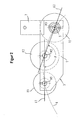
- FIG. 2 shows the arrangement of the three support rollers R1 to R3 FIG. 1 on a common reel holder 3, which has two pivotable retaining arms 5, each of which rotatably supports one end of the reels R1 to R3 (corresponding to FIG FIG. 2 only one arm 5 to see).
- Each support arm 5 is rigidly coupled in the preferred embodiment with a pivot lever 7. By means of this pivoting lever 7, the entire roll holder 3 can be pivoted about the pivot axis S around.
- the support rollers R1 to R3 are indeed rotatable on the support arms 5, but not slidably mounted. Rather, they have a specific and fixed geometric positional relationship relative to one another: a straight line G1 connects the centers of the two rollers R1 and R2, and a straight line G2 connects the centers of the two rollers R2 and R3.
- the straight lines G1 and G2 run at a fixed angle ⁇ not equal to 0 ° to each other.
- the angle ⁇ is 160.5 ° in this embodiment.
- the centers M1, M2 and M3 of the rollers R1, R2 and R3 lie on a circular arc K. This positional relationship between the support rollers R1 to R3 is fixed irrespective of which support roller is set in the working position.
- FIGS. 3 and 4 show the pipe support FIG. 2 in three different positions, each of which corresponds to the working position of one of the three rollers R1 to R3.
- FIG. 3 shows side views and FIG. 4 Front views of the pipe support.
- FIG. 3 also illustrates the position of the pivot axis S of the support arms 5 perpendicular to the conveying direction F of the extruded tubes.
- the extruded and to be supported pipes are also shown; they have different outside diameters. Note, however, that the central axis Z of the tubes always depends on the outer diameter same height runs. The pipes are therefore always centered.
- the center axis of the roller R3 coincides with the pivot axis S of the holding arms 5, so that the support roller R3 does not change its position relative to the central axis Z of the tubes.
- the pipe support for supporting pipes P1 is set with a first geometry, eg, an outer diameter of 90 mm.
- the first roller R1 is positioned in its working position, in which its support contour for contact with the outer circumference of the tubes DN90 is arranged.
- the support contour of the second roller R2 also comes in this position in contact with the outer circumference of the pipes DN90 and thus supports the pipes in addition.
- the support contour of the third roller does not come into contact with the outer circumference of these tubes.
- the pipe P1 (DN90) is in contact with the support contours SK1 and SK2 of the rollers R1 and R2, whereas the support contour SK3 of the roller R3 is clearly spaced from the outer circumference of the tube.
- the pipe support for supporting pipes P2 is set with a second, different from the first geometry, for example, an outer diameter of 110 mm.
- the support arm 5 are no longer positioned horizontally, but are pivoted with respect to the position a).
- the straight line G1 which connects the centers of the two first rollers R1 and R2, forms an angle ⁇ 1b with respect to the center axis Z of the tubes to be supported, while the straight line G2 forms an angle ⁇ 2b with respect to this central axis Z.
- the second roller R2 is positioned in its working position, in which its support contour for contact with the outer circumference of the tubes DN110 is arranged.
- the supporting contours of the first and third rollers R1 and R3 do not come into contact with the outer circumference of these tubes.
- the pipe P2 (DN110) is in contact with the support contour SK2 of the roller R2, while the support contours SK1 and SK3 of the rollers R1 and R3 are clearly spaced from the outer circumference of the tube.
- the pipe support is finally set to support pipes P3 having a third, different geometry from the first and second, eg an outer diameter of 140 mm.
- the holding arm 5 have been further pivoted with respect to the position b).
- the straight line G1 connecting the centers of the two first rollers R1 and R2 forms an angle ⁇ 1c with respect to the central axis Z of the tubes to be supported, while the straight line G2 forms an angle ⁇ 2c with respect to this central axis Z.
- the third roller R3 is positioned in its working position, in which its supporting contour is arranged for contact with the outer circumference of the tubes DN140.
- the supporting contours of the first and second rollers R1 and 23 do not come into contact with the outer circumference of these tubes.
- the pipe P3 (DN140) is in contact with the support contour SK3 of the roller R3, while the support contours SK1 and SK2 of the rollers R1 and R2 are clearly spaced from the outer circumference of the tube.
- the shape respective support contour SK1 to SK3 is particularly suitable for a particular pipe outside diameter, so that the pipes are fully supported in a portion of its outer periphery and any deformation of the freshly extruded pipes are prevented by the pipe support.
- FIG. 5 shows further details of the arrangement of the pipe support according to the invention in the extruder unit.
- the figure shows schematically the front view of a vacuum tank, which passes through the extruded tube.
- the inventive pipe support with the roll holder 3 and the three support rolls R1 to R3 described above is provided in the region of this vacuum tank in order to support the extruded pipes in a suitable manner.
- the figure also shows a linkage 11, which is coupled to one of the pivot lever 7 in a point of application 9, so that the roller holder 3 can be pivoted by means of this linkage 11.
- the roller holder 3 is in turn supported by two shaft ends 13 in the extrusion device, so that it can be pivoted overall about the pivot axis S around.
- FIG. 6 Finally, is a detailed view of the roller holder 3 with its holding arms 5, pivot levers 7 and shaft ends 13th
- the preferred embodiment is a pipe support for supporting plastic pipes
- the principle of the invention may also be applied to apparatus for extruding other types of plastic profiles.
- the present embodiment uses three support members in the form of three support rollers in a certain positional relationship to each other.
- the invention also covers embodiments with only two support elements.
- the preferred embodiment could be modified so that only the two rollers R1 and R2 or only the two rollers R2 and R3 are used. Also in this case could be made by suitable pivoting of the roller holder always the desired role in the working position.
Landscapes
- Engineering & Computer Science (AREA)
- Mechanical Engineering (AREA)
- Physics & Mathematics (AREA)
- Thermal Sciences (AREA)
- Extrusion Moulding Of Plastics Or The Like (AREA)
Applications Claiming Priority (1)
| Application Number | Priority Date | Filing Date | Title |
|---|---|---|---|
| DE102011079071A DE102011079071A1 (de) | 2011-07-13 | 2011-07-13 | Vorrichtung und Verfahren zur Unterstützung von Kunststoffprofilen sowie Extrusionslinie |
Publications (1)
| Publication Number | Publication Date |
|---|---|
| EP2546045A1 true EP2546045A1 (fr) | 2013-01-16 |
Family
ID=46545656
Family Applications (1)
| Application Number | Title | Priority Date | Filing Date |
|---|---|---|---|
| EP12176362A Withdrawn EP2546045A1 (fr) | 2011-07-13 | 2012-07-13 | Dispositif et procédé de soutien de profilés de matières synthétique dans des lignes d'extrusion |
Country Status (2)
| Country | Link |
|---|---|
| EP (1) | EP2546045A1 (fr) |
| DE (1) | DE102011079071A1 (fr) |
Cited By (3)
| Publication number | Priority date | Publication date | Assignee | Title |
|---|---|---|---|---|
| WO2015107093A1 (fr) * | 2014-01-15 | 2015-07-23 | Battenfeld-Cincinnati Germany Gmbh | Procédé et dispositif pour supporter un profilé en matière plastique |
| CN113830520A (zh) * | 2021-09-30 | 2021-12-24 | 广东顺塑塑料实业有限公司 | 一种塑料管材生产线的防跑偏装置 |
| CN119898013A (zh) * | 2025-04-01 | 2025-04-29 | 赣州恒信塑业有限公司 | 一种具备防粘连结构的塑料棒材挤出定型设备 |
Families Citing this family (2)
| Publication number | Priority date | Publication date | Assignee | Title |
|---|---|---|---|---|
| CN107777212A (zh) * | 2016-08-30 | 2018-03-09 | 天津市金丞泰节能建材科技有限公司 | 一种运输装置 |
| CN112478576B (zh) * | 2020-11-20 | 2022-03-29 | 中国机械工业机械工程有限公司 | 用于管道预制生产的纠偏矫正装置 |
Citations (8)
| Publication number | Priority date | Publication date | Assignee | Title |
|---|---|---|---|---|
| JPS4922964A (fr) * | 1972-06-19 | 1974-02-28 | ||
| US5580589A (en) * | 1992-10-26 | 1996-12-03 | British Gas Plc | Apparatus for bending plastic pipe |
| WO2004106034A1 (fr) | 2003-05-28 | 2004-12-09 | Krauss-Maffei Kunststofftechnik Gmbh | Rouleau combine pour installation d'extrusion de tuyaux |
| DE102004059515B3 (de) * | 2004-12-10 | 2006-05-11 | Inoex Gmbh | Vorrichtung zur Unterstützung von extrudierten Kunststoffprofilen, insbesondere Rohren, in einer Extrusionslinie |
| DE102006044643A1 (de) | 2006-09-21 | 2008-04-03 | Inoex Gmbh | Vorrichtung zur Unterstützung von Kunststoffprofilen |
| EP1955838A2 (fr) | 2007-02-09 | 2008-08-13 | INOEX GmbH | Dispositif destiné au soutien de profilés en plastique |
| DE102008028641A1 (de) * | 2008-06-18 | 2009-12-24 | Battenfeld Extrusionstechnik Gmbh | Vorrichtung und Verfahren zum Stützen eines Kunststoffprofiles |
| EP2255946A1 (fr) | 2009-05-30 | 2010-12-01 | INOEX GmbH | Dispositif et procédé de soutien de tuyaux dans des lignes d'extrusion |
Family Cites Families (2)
| Publication number | Priority date | Publication date | Assignee | Title |
|---|---|---|---|---|
| US5645861A (en) * | 1995-08-07 | 1997-07-08 | The Conair Group, Inc. | Guide roller assembly for a vacuum sizing tank |
| DE102005020296B4 (de) * | 2005-04-30 | 2010-06-02 | Battenfeld Extrusionstechnik Gmbh | Vorrichtung für die Profilextrusion |
-
2011
- 2011-07-13 DE DE102011079071A patent/DE102011079071A1/de not_active Withdrawn
-
2012
- 2012-07-13 EP EP12176362A patent/EP2546045A1/fr not_active Withdrawn
Patent Citations (8)
| Publication number | Priority date | Publication date | Assignee | Title |
|---|---|---|---|---|
| JPS4922964A (fr) * | 1972-06-19 | 1974-02-28 | ||
| US5580589A (en) * | 1992-10-26 | 1996-12-03 | British Gas Plc | Apparatus for bending plastic pipe |
| WO2004106034A1 (fr) | 2003-05-28 | 2004-12-09 | Krauss-Maffei Kunststofftechnik Gmbh | Rouleau combine pour installation d'extrusion de tuyaux |
| DE102004059515B3 (de) * | 2004-12-10 | 2006-05-11 | Inoex Gmbh | Vorrichtung zur Unterstützung von extrudierten Kunststoffprofilen, insbesondere Rohren, in einer Extrusionslinie |
| DE102006044643A1 (de) | 2006-09-21 | 2008-04-03 | Inoex Gmbh | Vorrichtung zur Unterstützung von Kunststoffprofilen |
| EP1955838A2 (fr) | 2007-02-09 | 2008-08-13 | INOEX GmbH | Dispositif destiné au soutien de profilés en plastique |
| DE102008028641A1 (de) * | 2008-06-18 | 2009-12-24 | Battenfeld Extrusionstechnik Gmbh | Vorrichtung und Verfahren zum Stützen eines Kunststoffprofiles |
| EP2255946A1 (fr) | 2009-05-30 | 2010-12-01 | INOEX GmbH | Dispositif et procédé de soutien de tuyaux dans des lignes d'extrusion |
Cited By (4)
| Publication number | Priority date | Publication date | Assignee | Title |
|---|---|---|---|---|
| WO2015107093A1 (fr) * | 2014-01-15 | 2015-07-23 | Battenfeld-Cincinnati Germany Gmbh | Procédé et dispositif pour supporter un profilé en matière plastique |
| US10744698B2 (en) | 2014-01-15 | 2020-08-18 | Battenfeld-Cincinnati Germany Gmbh | Process and apparatus for supporting a plastic profile |
| CN113830520A (zh) * | 2021-09-30 | 2021-12-24 | 广东顺塑塑料实业有限公司 | 一种塑料管材生产线的防跑偏装置 |
| CN119898013A (zh) * | 2025-04-01 | 2025-04-29 | 赣州恒信塑业有限公司 | 一种具备防粘连结构的塑料棒材挤出定型设备 |
Also Published As
| Publication number | Publication date |
|---|---|
| DE102011079071A1 (de) | 2013-01-17 |
Similar Documents
| Publication | Publication Date | Title |
|---|---|---|
| EP2674279B1 (fr) | Procédé de cintrage d'un profil, profil, procédé de fabrication de pièces profilées cintrées, pièces profilée cintrée, dispositif de cintrage d'un profil et ligne d'extrusion et de cintrage | |
| EP0121077B2 (fr) | Machine à cintrer des tubes | |
| EP2546045A1 (fr) | Dispositif et procédé de soutien de profilés de matières synthétique dans des lignes d'extrusion | |
| DE102013012134A1 (de) | Vorrichtung zur Herstellung von inline gereckten Folien | |
| DE10324187A1 (de) | Kombirolle für Rohrextrusionsanlage | |
| EP3094466B1 (fr) | Procédé et dispositif pour supporter un profilé en matière plastique | |
| DE19901187C2 (de) | Vorrichtung zum kontinuierlichen Walzen eines Blechbandes zu einem Profil mit im Querschnitt geraden Profilschenkeln, insbesondere zum Herstellen eines längsgeschweißten Rechteckrohres | |
| EP1965965B1 (fr) | Installation d'extrusion pour feuille soufflee | |
| EP2510791A2 (fr) | Dispositif de formage d'une bande de pâte à partir de portions de pâtes alimentées | |
| EP1669185B1 (fr) | Dispositif pour supporter des profils en matière plastique extrudée, notamment tuyaux, dans une ligne d'extrusion | |
| DE102010010697A1 (de) | Walzwerk zum Herstellen von Rohren und Stäben oder dergleichen Langprodukten | |
| DE3001705C2 (de) | Zentriervorrichtung für Formwerkzeuge von Strangpressen | |
| EP2750816A1 (fr) | Dispositif de production destiné à fabriquer des produits à partir de tiges métalliques cylindriques | |
| DE102005051874B4 (de) | Blasfolienextrusionsanlage | |
| DE102014119205A1 (de) | Folienmaschine für die Herstellung von Stretchfolie | |
| EP1737641B1 (fr) | Dispositif de transport d'un film tubulaire | |
| EP3738740B1 (fr) | Dispositif de formation transversale d'une pluralité de faisceaux de fibres plastique parallèles | |
| EP1955838A2 (fr) | Dispositif destiné au soutien de profilés en plastique | |
| DE102020127066A1 (de) | Kalibrierkorb für blasfolienanlage | |
| DE60000888T2 (de) | Ein Verfahren und eine Vorrichtung zur kontinuierlichen Herstellung von Förderschnecken für Archimedesförderschnecken | |
| DE102006044643A1 (de) | Vorrichtung zur Unterstützung von Kunststoffprofilen | |
| DE202004019566U1 (de) | Führungskammer als Anfahrhilfe | |
| EP2153971A2 (fr) | Ligne d'extrusion pour tuyaux en matière synthétique | |
| AT515411B1 (de) | Vorrichtung zur Unterstützung von Kunststoffprofilen, insbesondere Rohren, in einer Extrusionsanlage sowie ein Verfahren zum Verändern eines Stützbereiches einer Stützvorrichtung | |
| EP2546044A1 (fr) | Dispositif d'extrusion de tuyau et procédé d'extrusion de tuyaux en plastique |
Legal Events
| Date | Code | Title | Description |
|---|---|---|---|
| PUAI | Public reference made under article 153(3) epc to a published international application that has entered the european phase |
Free format text: ORIGINAL CODE: 0009012 |
|
| AK | Designated contracting states |
Kind code of ref document: A1 Designated state(s): AL AT BE BG CH CY CZ DE DK EE ES FI FR GB GR HR HU IE IS IT LI LT LU LV MC MK MT NL NO PL PT RO RS SE SI SK SM TR |
|
| AX | Request for extension of the european patent |
Extension state: BA ME |
|
| STAA | Information on the status of an ep patent application or granted ep patent |
Free format text: STATUS: THE APPLICATION IS DEEMED TO BE WITHDRAWN |
|
| 18D | Application deemed to be withdrawn |
Effective date: 20130717 |