EP2546046A2 - Moyen de transport pour récipients et procédé de transport de récipients - Google Patents
Moyen de transport pour récipients et procédé de transport de récipients Download PDFInfo
- Publication number
- EP2546046A2 EP2546046A2 EP12167302A EP12167302A EP2546046A2 EP 2546046 A2 EP2546046 A2 EP 2546046A2 EP 12167302 A EP12167302 A EP 12167302A EP 12167302 A EP12167302 A EP 12167302A EP 2546046 A2 EP2546046 A2 EP 2546046A2
- Authority
- EP
- European Patent Office
- Prior art keywords
- container
- transport
- vehicles
- containers
- shell molds
- Prior art date
- Legal status (The legal status is an assumption and is not a legal conclusion. Google has not performed a legal analysis and makes no representation as to the accuracy of the status listed.)
- Withdrawn
Links
- 238000000034 method Methods 0.000 title claims abstract description 9
- 230000002093 peripheral effect Effects 0.000 claims description 7
- 238000010000 carbonizing Methods 0.000 claims description 2
- 238000007664 blowing Methods 0.000 description 18
- 238000012546 transfer Methods 0.000 description 11
- 239000000463 material Substances 0.000 description 10
- 238000004519 manufacturing process Methods 0.000 description 6
- 230000008859 change Effects 0.000 description 3
- 230000000052 comparative effect Effects 0.000 description 3
- 238000010276 construction Methods 0.000 description 3
- 238000013461 design Methods 0.000 description 3
- 230000002349 favourable effect Effects 0.000 description 3
- 230000007246 mechanism Effects 0.000 description 3
- 235000013361 beverage Nutrition 0.000 description 2
- 238000003763 carbonization Methods 0.000 description 2
- 239000000969 carrier Substances 0.000 description 2
- 230000008878 coupling Effects 0.000 description 2
- 238000010168 coupling process Methods 0.000 description 2
- 238000005859 coupling reaction Methods 0.000 description 2
- 238000010438 heat treatment Methods 0.000 description 2
- 206010053648 Vascular occlusion Diseases 0.000 description 1
- 230000008901 benefit Effects 0.000 description 1
- 238000000071 blow moulding Methods 0.000 description 1
- 235000014171 carbonated beverage Nutrition 0.000 description 1
- 238000011161 development Methods 0.000 description 1
- 230000018109 developmental process Effects 0.000 description 1
- 238000007373 indentation Methods 0.000 description 1
- 238000002372 labelling Methods 0.000 description 1
- 239000007788 liquid Substances 0.000 description 1
- 230000007257 malfunction Effects 0.000 description 1
- 230000008569 process Effects 0.000 description 1
- 238000012545 processing Methods 0.000 description 1
- 239000000047 product Substances 0.000 description 1
- 238000011084 recovery Methods 0.000 description 1
- 239000013589 supplement Substances 0.000 description 1
Images


Classifications
-
- B—PERFORMING OPERATIONS; TRANSPORTING
- B29—WORKING OF PLASTICS; WORKING OF SUBSTANCES IN A PLASTIC STATE IN GENERAL
- B29C—SHAPING OR JOINING OF PLASTICS; SHAPING OF MATERIAL IN A PLASTIC STATE, NOT OTHERWISE PROVIDED FOR; AFTER-TREATMENT OF THE SHAPED PRODUCTS, e.g. REPAIRING
- B29C49/00—Blow-moulding, i.e. blowing a preform or parison to a desired shape within a mould; Apparatus therefor
- B29C49/42—Component parts, details or accessories; Auxiliary operations
- B29C49/4205—Handling means, e.g. transfer, loading or discharging means
- B29C49/42069—Means explicitly adapted for transporting blown article
-
- B—PERFORMING OPERATIONS; TRANSPORTING
- B29—WORKING OF PLASTICS; WORKING OF SUBSTANCES IN A PLASTIC STATE IN GENERAL
- B29C—SHAPING OR JOINING OF PLASTICS; SHAPING OF MATERIAL IN A PLASTIC STATE, NOT OTHERWISE PROVIDED FOR; AFTER-TREATMENT OF THE SHAPED PRODUCTS, e.g. REPAIRING
- B29C33/00—Moulds or cores; Details thereof or accessories therefor
- B29C33/20—Opening, closing or clamping
- B29C33/202—Clamping means operating on closed or nearly closed mould parts, the clamping means being independently movable of the opening or closing means
-
- B—PERFORMING OPERATIONS; TRANSPORTING
- B29—WORKING OF PLASTICS; WORKING OF SUBSTANCES IN A PLASTIC STATE IN GENERAL
- B29C—SHAPING OR JOINING OF PLASTICS; SHAPING OF MATERIAL IN A PLASTIC STATE, NOT OTHERWISE PROVIDED FOR; AFTER-TREATMENT OF THE SHAPED PRODUCTS, e.g. REPAIRING
- B29C33/00—Moulds or cores; Details thereof or accessories therefor
- B29C33/34—Moulds or cores; Details thereof or accessories therefor movable, e.g. to or from the moulding station
- B29C33/36—Moulds or cores; Details thereof or accessories therefor movable, e.g. to or from the moulding station continuously movable in one direction, e.g. in a closed circuit
-
- B—PERFORMING OPERATIONS; TRANSPORTING
- B29—WORKING OF PLASTICS; WORKING OF SUBSTANCES IN A PLASTIC STATE IN GENERAL
- B29C—SHAPING OR JOINING OF PLASTICS; SHAPING OF MATERIAL IN A PLASTIC STATE, NOT OTHERWISE PROVIDED FOR; AFTER-TREATMENT OF THE SHAPED PRODUCTS, e.g. REPAIRING
- B29C49/00—Blow-moulding, i.e. blowing a preform or parison to a desired shape within a mould; Apparatus therefor
- B29C49/42—Component parts, details or accessories; Auxiliary operations
- B29C49/4205—Handling means, e.g. transfer, loading or discharging means
- B29C49/42093—Transporting apparatus, e.g. slides, wheels or conveyors
- B29C49/42097—Sliding rails, e.g. inclined
-
- B—PERFORMING OPERATIONS; TRANSPORTING
- B29—WORKING OF PLASTICS; WORKING OF SUBSTANCES IN A PLASTIC STATE IN GENERAL
- B29C—SHAPING OR JOINING OF PLASTICS; SHAPING OF MATERIAL IN A PLASTIC STATE, NOT OTHERWISE PROVIDED FOR; AFTER-TREATMENT OF THE SHAPED PRODUCTS, e.g. REPAIRING
- B29C49/00—Blow-moulding, i.e. blowing a preform or parison to a desired shape within a mould; Apparatus therefor
- B29C49/42—Component parts, details or accessories; Auxiliary operations
- B29C49/4236—Drive means
- B29C49/42362—Electric drive means, e.g. servomotors
-
- B—PERFORMING OPERATIONS; TRANSPORTING
- B29—WORKING OF PLASTICS; WORKING OF SUBSTANCES IN A PLASTIC STATE IN GENERAL
- B29C—SHAPING OR JOINING OF PLASTICS; SHAPING OF MATERIAL IN A PLASTIC STATE, NOT OTHERWISE PROVIDED FOR; AFTER-TREATMENT OF THE SHAPED PRODUCTS, e.g. REPAIRING
- B29C49/00—Blow-moulding, i.e. blowing a preform or parison to a desired shape within a mould; Apparatus therefor
- B29C49/42—Component parts, details or accessories; Auxiliary operations
- B29C49/56—Opening, closing or clamping means
-
- B—PERFORMING OPERATIONS; TRANSPORTING
- B65—CONVEYING; PACKING; STORING; HANDLING THIN OR FILAMENTARY MATERIAL
- B65G—TRANSPORT OR STORAGE DEVICES, e.g. CONVEYORS FOR LOADING OR TIPPING, SHOP CONVEYOR SYSTEMS OR PNEUMATIC TUBE CONVEYORS
- B65G21/00—Supporting or protective framework or housings for endless load-carriers or traction elements of belt or chain conveyors
- B65G21/20—Means incorporated in, or attached to, framework or housings for guiding load-carriers, traction elements or loads supported on moving surfaces
- B65G21/22—Rails or the like engaging sliding elements or rollers attached to load-carriers or traction elements
-
- B—PERFORMING OPERATIONS; TRANSPORTING
- B29—WORKING OF PLASTICS; WORKING OF SUBSTANCES IN A PLASTIC STATE IN GENERAL
- B29C—SHAPING OR JOINING OF PLASTICS; SHAPING OF MATERIAL IN A PLASTIC STATE, NOT OTHERWISE PROVIDED FOR; AFTER-TREATMENT OF THE SHAPED PRODUCTS, e.g. REPAIRING
- B29C2949/00—Indexing scheme relating to blow-moulding
- B29C2949/07—Preforms or parisons characterised by their configuration
- B29C2949/0715—Preforms or parisons characterised by their configuration the preform having one end closed
-
- B—PERFORMING OPERATIONS; TRANSPORTING
- B29—WORKING OF PLASTICS; WORKING OF SUBSTANCES IN A PLASTIC STATE IN GENERAL
- B29C—SHAPING OR JOINING OF PLASTICS; SHAPING OF MATERIAL IN A PLASTIC STATE, NOT OTHERWISE PROVIDED FOR; AFTER-TREATMENT OF THE SHAPED PRODUCTS, e.g. REPAIRING
- B29C49/00—Blow-moulding, i.e. blowing a preform or parison to a desired shape within a mould; Apparatus therefor
- B29C49/02—Combined blow-moulding and manufacture of the preform or the parison
- B29C49/06—Injection blow-moulding
-
- B—PERFORMING OPERATIONS; TRANSPORTING
- B29—WORKING OF PLASTICS; WORKING OF SUBSTANCES IN A PLASTIC STATE IN GENERAL
- B29C—SHAPING OR JOINING OF PLASTICS; SHAPING OF MATERIAL IN A PLASTIC STATE, NOT OTHERWISE PROVIDED FOR; AFTER-TREATMENT OF THE SHAPED PRODUCTS, e.g. REPAIRING
- B29C49/00—Blow-moulding, i.e. blowing a preform or parison to a desired shape within a mould; Apparatus therefor
- B29C49/28—Blow-moulding apparatus
- B29C49/30—Blow-moulding apparatus having movable moulds or mould parts
- B29C49/36—Blow-moulding apparatus having movable moulds or mould parts rotatable about one axis
-
- B—PERFORMING OPERATIONS; TRANSPORTING
- B29—WORKING OF PLASTICS; WORKING OF SUBSTANCES IN A PLASTIC STATE IN GENERAL
- B29C—SHAPING OR JOINING OF PLASTICS; SHAPING OF MATERIAL IN A PLASTIC STATE, NOT OTHERWISE PROVIDED FOR; AFTER-TREATMENT OF THE SHAPED PRODUCTS, e.g. REPAIRING
- B29C49/00—Blow-moulding, i.e. blowing a preform or parison to a desired shape within a mould; Apparatus therefor
- B29C49/42—Component parts, details or accessories; Auxiliary operations
- B29C49/4273—Auxiliary operations after the blow-moulding operation not otherwise provided for
- B29C49/428—Joining
- B29C49/42802—Joining a closure or a sealing foil to the article or pincing the opening
-
- B—PERFORMING OPERATIONS; TRANSPORTING
- B29—WORKING OF PLASTICS; WORKING OF SUBSTANCES IN A PLASTIC STATE IN GENERAL
- B29C—SHAPING OR JOINING OF PLASTICS; SHAPING OF MATERIAL IN A PLASTIC STATE, NOT OTHERWISE PROVIDED FOR; AFTER-TREATMENT OF THE SHAPED PRODUCTS, e.g. REPAIRING
- B29C49/00—Blow-moulding, i.e. blowing a preform or parison to a desired shape within a mould; Apparatus therefor
- B29C49/42—Component parts, details or accessories; Auxiliary operations
- B29C49/4273—Auxiliary operations after the blow-moulding operation not otherwise provided for
- B29C49/42808—Filling the article
Definitions
- the invention relates to a means of transport for containers, a method for transporting containers with the means of transport according to the invention and a container suitable for transport with the means of transport according to the invention.
- An alternative transport concept can be derived, for example, from blow molding machines in which the containers are held and transported by the mold halves immediately after blowing.
- blow molding machines in which the containers are held and transported by the mold halves immediately after blowing.
- it is from the EP 1226017 B1 known to arrange two each with respect to the transport direction of the Blasrads oppositely arranged blow mold halves on a common mold carrier.
- By pivoting the blow mold carriers on the blow wheel an approximately stationary gap between adjacent mold carriers can be provided to introduce parisons between the blow mold halves and remove the finished blown bottles from them.
- comparatively complicated holding mechanisms of the mold carrier are required on the blowing wheel, such as radially extendable retaining arms.
- such a transport system is not yet available for use in other plant areas of bottling plants.
- this independently driven vehicles in particular slides, comprises a guide device for the circumferential guidance of the vehicles and mold shells for enclosing the container in an at least substantially peripheral portion of its side wall.
- the mold shells are mounted on the vehicles to receive and transport the containers between the shell molds of adjacent vehicles.
- the fact that the containers are enclosed by the shell molds, holding devices in the neck region of the container can be dispensed with or can be simplified.
- the neck area of the container can be relieved during transport, so that support rings in the neck area can be dispensed with or can be produced with less material.
- the independent drive of the vehicles allows movement patterns for opening, closing the holding devices and for transporting the at least substantially enclosed containers.
- vehicles means means of transport, such as carriages or carriages, to be understood, which in themselves have a transport function, so that they can be separated at least in sections of the means of transport of adjacent vehicles.
- the guide device includes, for example, rails, railings, baffles, switches and the like.
- the shell molds can support the containers, in particular in their bottom region from below.
- the enclosing of the containers preferably comprises a positive engagement with the outer wall of the containers.
- the guide device is longer than the juxtaposed vehicles to form at least one non-rotating, in particular approximately stationary, gap between the rotating vehicles for introducing and / or removing the container.
- This allows the containers in a lateral direction, in particular in a radial direction, are removed from the transport and / or introduced into this.
- the juxtaposed vehicles within a predetermined portion of the transport means are first separated one after the other in the transport direction and then moved together again.
- a particularly favorable embodiment further comprises an active drive means provided for the vehicles, in particular comprising linear motor modules, provided on the guide device.
- the vehicles can essentially be designed as reactive, in particular passive drive components. This simplifies the construction and enables a modular construction of the vehicles, in particular a simple replacement of the plurality of vehicles.
- Linear motor modules are particularly suitable for a sectionally individually controllable drive of the vehicles. In this case, the vehicles are preferably transferred from a linear motor module to the linear motor module following in the transport direction.
- the vehicles preferably include reactive drive means cooperating with the active drive means, in particular permanent magnets.
- the control of the vehicles can be simplified.
- Under reactive here is to understand a central control of the transport movement by means of the active drive means.
- the vehicles can be trained as passive drive components.
- two respective shell molds opposite the transport direction of the containers are mounted on a vehicle.
- a stream of enclosed containers can be transported between molded shell molds.
- Adjacent shell molds thus form a holding device for the container, which can be opened in a simple manner by moving apart of the vehicles and can close by moving the vehicles together. When opening and closing it is thus possible to realize particularly simple movement patterns.
- the vehicles can be driven together to circumferentially completely enclose an intermediate container with two shell molds.
- the container can be guided such that a support ring on the container and a corresponding holding device on the means of transport are dispensable.
- locking means are provided on the shell molds to secure the enclosed containers against rotation about their major axis.
- the container can be held in a predetermined rotational position during closing, in particular when screwing.
- the locking means may for example be a survey or depression, which engages in a corresponding depression or elevation of the container.
- the locking means is thus preferably positive fit, but could also be non-positive.
- the shell molds are designed to support the enclosed container against a filling pressure for carbonizing from the outside.
- the means of transport can be integrated into a carbonated beverage filling device.
- the containers can be filled and carbonated during transport in the shell molds.
- the container can be supported by the fact that the shell molds have wall portions which are formed as a negative of the container shape.
- the shell molds are formed as blow mold halves.
- the means of transport can be integrated into a device for blowing and / or stretch blowing the container.
- the shell molds could laterally grip the containers and be supplemented by a bottom mold for blowing the containers.
- a locking means is preferably provided, for example with clips or the like, to seal the shell molds against the blowing pressure.
- the shell molds are adapted to hold the enclosed container below a neck portion of the container laterally.
- a support ring on the containers can be dispensed with.
- the containers can thus be manufactured in the mouth area with a reduced use of material.
- containers with differently shaped neck areas, mouths and closures can be transported.
- the stated object is further achieved by a method according to claim 11, for transporting the containers with the means of transport according to the invention.
- the method comprises the steps of: enclosing the containers in a peripheral portion of their side wall with the shell mold; Transporting the containers between shell molds of respectively adjacent vehicles; and moving apart of the adjacent vehicles in order to remove the containers from the means of transport, wherein the containers are blown and / or filled and / or closed, in particular during transport.
- the speed of circulation of the vehicles for loading and / or unloading the containers is varied with respect to respective leading and trailing vehicles in order to form a non-circumferential gap between the vehicles. This allows the gap between a first pair of vehicles to close while opening between an adjacent pair of vehicles.
- the containers are blown during transport and / or filled and / or closed. This makes it possible to provide a flexible transport method for containers, which can be integrated into different production steps in filling systems.
- a container according to claim 13 in particular with a container made of plastic, which is suitable for transport with the means of transport according to the invention.
- a container made of plastic which is suitable for transport with the means of transport according to the invention.
- at least one circumferential portion of the container outer wall is formed as a negative of an inner wall portion of the shell molds.
- the container wall in the entire region of the mouth opening measured in a direction perpendicular to the main axis of the container, not thicker than 2 mm, in particular not thicker than 1 mm.
- the container can be manufactured with a particularly low material usage.
- the mouth area can be designed for different closure types.
- the container according to the invention further comprises a sealed in the mouth opening closure, which preferably consists of the same material as the container, wherein on the closure in particular a tear-off tab or the like is provided for opening the container.
- a sealed in the mouth opening closure which preferably consists of the same material as the container, wherein on the closure in particular a tear-off tab or the like is provided for opening the container.
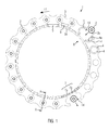
- the vehicles 3 run on suitable bearings 3a, trolleys or the like along a guide device 5, such as a rail to.
- an active drive means 7 is integrated, which comprises, for example, lined up linear motor modules. These interact with reactive, in particular passive drive means 9, which are provided on the vehicles 3.
- the active drive means 7 extends completely along the guide means 5.
- a plurality of linear motor modules are provided at a suitable distance from each other along the transport direction 11 on the transport means 1.
- Fig. 1 For simplicity, only two circumferential segments 7a, 7b, for example in the form of adjacent linear motor modules, of the drive means 7 are shown. Likewise, the reactive drive means 9 is indicated only on one of the illustrated vehicles 3.
- the active drive means 7 and the reactive drive means 9 cooperate in such a way that a continuous transport of the vehicles 3 along the transport direction 11 is made possible. Accordingly, in a segmented construction of the active drive means 7, for example in the form of individual linear motor modules, it is ensured that the reactive drive means 9 are transferred from one segment 7a to the next segment 7b.
- the guide device 5 along the transport direction 11 is longer than the juxtaposed vehicles 3 to form at least one gap 13, 14 between adjacent vehicles 3, at which the container 2 can be introduced into the transport 1 and / or removed from this .
- a first, with respect to the transport direction 11 substantially stationary gap 13 for introducing the container 2 is provided, and a second, with respect to the transport direction 11 substantially stationary gap 14 for removing the container 2.
- the gaps 13, 14 are provided by the Speed of at least one vehicle 3 in the region of the gap 13, 14 opposite leading vehicles 3 and / or subsequent vehicles 3 is changed. For example, a first vehicle 3 could be accelerated in the region of the gap 13, 14 with respect to a second, following vehicle 3 in order to open the gap 13, 14.
- the second vehicle 3 is compared to the leading first vehicle 3 and accelerated this docked, so that the container 2 is held between adjacent mold halves 4.
- the mold halves 4 surround the container 2 preferably in full.
- the mold halves 4 only enclose a peripheral portion of the container side wall 2a.
- an additional holding of the container 2 in the vertical direction is advantageous.
- the vehicles 3 are driven individually and independently of each other.
- the shell molds 4 can be mounted replaceably on the vehicles 3. It would thus be possible to form the shell molds 4 as interchangeable set parts, so that would have to be changed in a production change to another type of container, for example, only the shell molds. However, it would also be conceivable to carry out the vehicles 3 quickly exchangeable in order to be able to change them during a product change and / or a malfunction.
- Fig. 1 also clarified, preferably two of each pioneering mold halves 4 are provided on the vehicles 3.
- the means of transport 1 in the region of the gaps 13, 14 can be opened and closed simultaneously by simply moving a respective individual vehicle 3 relative to the adjacent vehicles 3. It would also be conceivable to provide a separate vehicle 3 for each mold half 4. In this case, the opening and closing of the transport means 1 in the region of the gaps 13, 14 could be decoupled in time.
- the guide device 5 is arranged radially inwardly with respect to the curvature of the transport path. This simplifies the introduction and removal of the container in a lateral, in particular radial direction R outwards. Depending on the application, it would also be conceivable to arrange the guide device 5 in a region below or above the mold halves 4.
- the mold halves 4 may include an inner holding portion 4a, which is formed substantially as a negative of the container contour 2b.
- the container 2 enclosed by the mold halves 4 can be locked in the vertical direction V.
- a support ring on the container 2 and a corresponding holding device on the transport means 1 is unnecessary.
- the inner holding portion 4a of the shell molds 4 and the outer contour 2b of the container 2 to be held are matched to one another in such a way that the container 2 is supported against a filling pressure during the carbonation of a beverage to be filled in the container 2. That is, a dimensional tolerance is maintained between the outer contour 2b of the container 2 and the inner holding portion 4a of the shell molds 4, which avoids unacceptable expansion of the container 2 during carbonization.
- a locking means 17 may be provided on the shell molds 4, for example in the form of a projection in the bottom region of one of the corresponding shell molds 4, which engages in a corresponding recess in the container 2, to rotate the container 2 about its main axis 2c relative to the Mold shell 4 to prevent.
- the container 2 can be transported and treated in a predetermined rotational position. This allows a closure of the container 2 during transport, in particular by screwing a (not shown) cap.
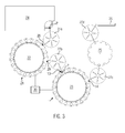
- the Fig. 3 illustrates that the transport means according to the invention for the container transport can be used in different treatment stations of a bottling plant.
- the transport means according to the invention is provided at a blowing station 22 and according to the first embodiment 1 at a filling station 23. Also indicated are a heating module 24 for preforms 2 ', a closing station 25, a discharge device 26 and transfer devices 27a-27d Transfer of the preforms 2 'from the heating module 24 to the blowing station 22 and the transfer of containers 2 between the other stations.
- the transport means 1, 21 can operate substantially on the same principle of operation.
- the blow station 22 and the filling station 23 each have a non-circumferential gap 28, 13 for introducing preforms 2 'or containers 2 and a non-circumferential gap 29, 14 for removing the respective container 2.
- These approximately stationary gaps 13, 14th , 28, 29 may, however, be provided in different circumferential subregions of the respective transport means 1, 21 in order, for example, to utilize the largest possible machine angle for blowing the containers 2 at the blowing station 22.
- the transfer devices 27a-27d can alternatively be replaced by a continuous transport with the means of transport 1, 21 according to the invention.
- this has the advantage that the containers 2 are held continuously and all handover problems is excluded.
- it is necessary to carry out continuously the guide device 5 with the active drive means 7, ie from the blowing station 22 via the filling station 23 to the closing station 25, as far as these are present in the arrangement.
- a control unit 30 is provided to control at least one inventive transport means 1, 21.
- the control unit 30 serves to coordinate the circulating movements of the individual vehicles 3 in such a way that approximately fixed gaps 13, 14, 28, 29 for introducing and removing preforms 2 'or containers 2 are provided in predetermined circumferential partial regions or machine angle regions, and Between the gaps 13, 14 and 28, 29 transport routes are provided, in which the container 2 are enclosed by the shell molds 4 and thus transported by the vehicles 3 circulating.
- treatment steps such as, for example, blowing the containers 2, filling the containers 2 and / or closing the containers 2 can be carried out.
- the containers 2 and / or the preforms 2 ' may be transferred by known transfer devices 27a-27d, such as transfer starwheels.
- transfer devices 27a-27d such as transfer starwheels.
- the transport means 1, 21 according to the invention can be integrated into different production facilities for bottling beverages.
- FIGS. 4A and 4B show a preferred embodiment 32 of a container according to the invention, comprising a container body 32a made of plastic, for example made of PET, and a welded to the container body 32a closure 32b.
- a tear tab 32c is preferably provided with which the closure 32b or at least a portion of the closure 32b can be pulled off to open the container 32.
- no support ring is provided on the container 32.
- the otherwise usual plastic bottles screw cap is unnecessary.
- the outer contour 32d of the container 32 at least partially corresponds to the contour of the inner holding portion 4a of the mold halves 4.
- a locking means 32e may be provided in the region of the outer contour 32d or in the region of the container bottom 32f, preferably as a recess or indentation in the container 32 specify the rotational position of the container 32. This may be advantageous, for example, when labeling the container 32.
- the container 32 according to the invention in cooperation with the shell molds 4 allows a guide and holding the container 32 in the region of the outer contour 32d and locking the rotational position of the container 32 with respect to the shell molds 4 by means of the locking means 32e, 17.
- the container 32 no structures for Carrying and / or locking the container 32 may be provided.
- the welded closure 32b can be produced in a simple manner and with little use of material.
- the mouth region 32g of the container 32 can be made particularly thin-walled.
- the wall thickness is preferably less than 2 mm, in particular less than 1 mm.
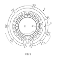
- FIG. 5 a comparative example shown with a transport 41, in which radially inner blow mold halves 42 are fixedly mounted on a blowing wheel 43, while radially outer blow mold halves 44 move in a separate transport circuit along a peripheral portion of the Blasrads 43 with the radially inner blow mold halves 42 and each case with a corresponding inner blow mold half 42 close a blow mold.
- the circuit for the radially outer blow mold halves can be realized by a transport system 45, comprising a guide device with an active drive means and passively operated vehicles for supporting the outer blow mold halves 44.
- a transport system 45 comprising a guide device with an active drive means and passively operated vehicles for supporting the outer blow mold halves 44.
- a transport system 45 comprising a guide device with an active drive means and passively operated vehicles for supporting the outer blow mold halves 44.
- containers 2 to be filled are supplied continuously from the transfer device 27b in the region of the gap 13 between adjacent mold halves 4.
- a vehicle 3 is docked in the region of the gap 13 with an increased rotational speed to the respectively preceding vehicle 3 in order to open the gap 13.
- a container 2 can be introduced from the transfer device 27b into the gap 13.
- the forwardly running mold shell 4 it is also possible for the forwardly running mold shell 4 to continue with the vehicle 3 temporarily with a reduced transport speed or is temporarily stationary with respect to the gap 13.
- corresponding pivoting devices and / or telescoping devices are provided on the transfer device 27b in order to bring the container 2 into contact with the leading mold shell 4.
- the vehicle 3 can be moved with the trailing mold shell 4 to the container 2.
- the rotational speed of the trailing shell mold 4 and the associated vehicle 3 is temporarily increased.
- This automatically opens the gap 13 to the following vehicle 3, in turn, a container 2 can be introduced.
- the approximately stationary gap 13 can thus move back and forth in a defined machine angle range with respect to the transport direction 11.
- the term stationary is therefore understood to mean non-circumferential and defines an area, in particular a machine angle range, which does not leave the gap 13 to the movements for opening the transport means 1, for receiving the container 2 between the mold shells 4 and closing the Transport means 1 perform.
- the respective container 2 After closing the gap 13, the respective container 2 is transported further circumferentially between the shell molds 4, so that the respective production step, such as the filling of the bottle, can be carried out during the transport of the container 2.
- the respective production step such as the filling of the bottle
- this is opened following the movement scheme previously described for the gap 13 in order to remove the container 2 and to transfer it to the transfer device 27c for further processing.
- the gaps 14, 28 and 29 can be provided in the same way as the gap 13 described in detail. However, it is possible to supplement the described movements of the vehicles 3 and the shell molds 4 by additional opening and / or closing movements, for example by raising and lowering a bottom mold in the area of blow station 22.
- the vehicles 3 can be connected to each other. Either this is done on the shell molds 4 or the reactive drive means 9, or their holder. This can be done by suitable locking mechanisms after the introduction of the container 2. It may be a simple latch, a magnetic coupling, a vacuum coupling or other non-positive or positive connection, which is canceled shortly before the opening of the shell molds 4 again. In particular, the linear motor modules are thereby not exposed to sections, additional forces.
Landscapes
- Engineering & Computer Science (AREA)
- Mechanical Engineering (AREA)
- Manufacturing & Machinery (AREA)
- Filling Of Jars Or Cans And Processes For Cleaning And Sealing Jars (AREA)
- Blow-Moulding Or Thermoforming Of Plastics Or The Like (AREA)
- Specific Conveyance Elements (AREA)
- Branching, Merging, And Special Transfer Between Conveyors (AREA)
Applications Claiming Priority (1)
| Application Number | Priority Date | Filing Date | Title |
|---|---|---|---|
| DE102011079076A DE102011079076A1 (de) | 2011-07-13 | 2011-07-13 | Transportmittel für Behälter und Verfahren zum Transport von Behältern |
Publications (2)
| Publication Number | Publication Date |
|---|---|
| EP2546046A2 true EP2546046A2 (fr) | 2013-01-16 |
| EP2546046A3 EP2546046A3 (fr) | 2014-04-02 |
Family
ID=46178409
Family Applications (1)
| Application Number | Title | Priority Date | Filing Date |
|---|---|---|---|
| EP12167302.4A Withdrawn EP2546046A3 (fr) | 2011-07-13 | 2012-05-09 | Moyen de transport pour récipients et procédé de transport de récipients |
Country Status (4)
| Country | Link |
|---|---|
| US (1) | US9193108B2 (fr) |
| EP (1) | EP2546046A3 (fr) |
| CN (1) | CN102874591B (fr) |
| DE (1) | DE102011079076A1 (fr) |
Families Citing this family (11)
| Publication number | Priority date | Publication date | Assignee | Title |
|---|---|---|---|---|
| JP6280136B2 (ja) * | 2012-12-19 | 2018-02-14 | ディスクマ アクチェンゲゼルシャフト | 容器の製造装置及び製造方法 |
| SI2944588T1 (sl) * | 2014-05-16 | 2017-03-31 | Khs Gmbh | Transportno zvezdasto kolo z magneti za razstavljivo povezavo transportnega zvezdastega kolesa z vrtilno osjo |
| EP3510459B1 (fr) | 2016-09-09 | 2026-04-22 | The Procter & Gamble Company | Système et procédé pour l'acheminement indépendant de véhicules chargés de conteneurs pour créer différents produits finis |
| MX2019002775A (es) * | 2016-09-09 | 2019-08-29 | Procter & Gamble | Soporte de vacío con junta de falda extensible. |
| MX391753B (es) | 2016-09-09 | 2025-03-19 | Procter & Gamble | Sistema de báscula de pesaje en movimiento y método para cinta transportadora con motor sincrónico lineal. |
| WO2018049119A1 (fr) | 2016-09-09 | 2018-03-15 | The Procter & Gamble Company | Procédés de production simultanée de produits différents sur une seule ligne de production |
| CN109661366B (zh) | 2016-09-09 | 2022-01-14 | 宝洁公司 | 用于独立地引导载具并且将容器和闭合件递送到单元操作站的系统和方法 |
| US10558201B2 (en) | 2016-09-09 | 2020-02-11 | The Procter & Gamble Company | System and method for producing products based upon demand |
| CA3035537C (fr) | 2016-09-09 | 2021-07-20 | The Procter & Gamble Company | Systeme et procede de remplissage simultane de recipients de formes et/ou de tailles differentes |
| CN109661352B (zh) | 2016-09-09 | 2021-12-03 | 宝洁公司 | 用于用不同的流体组合物同时填充容器的系统和方法 |
| CN108896553A (zh) * | 2018-06-04 | 2018-11-27 | 合肥市雅视智能科技有限公司 | 一种大批量零部件全方位检测装置 |
Citations (3)
| Publication number | Priority date | Publication date | Assignee | Title |
|---|---|---|---|---|
| DE3008154A1 (de) * | 1980-03-04 | 1981-09-10 | Desma-Werke Gmbh, 2807 Achim | Formvorrichtung mit einer mehrzahl von jeweils mehrteiligen formen, z.b. giess- oder vulkanisierformen |
| EP1226017B1 (fr) | 1999-10-08 | 2006-03-29 | SIG Corpoplast GmbH & Co. KG | Procede et dispositif de formage par soufflage de contenants |
| DE60208936T2 (de) | 2001-02-12 | 2006-08-24 | Graham Packaging Plastic Products Inc. | Blasformverfahren und Blasformvorrichtung mit Formförderwagen |
Family Cites Families (18)
| Publication number | Priority date | Publication date | Assignee | Title |
|---|---|---|---|---|
| US1842411A (en) * | 1929-05-29 | 1932-01-26 | Lester L Ladd | Monorail conveyer for annular kilns |
| DE1232331B (de) * | 1961-02-21 | 1967-01-12 | Grisebach Hans Theodor | Vorrichtung und Verfahren zum Herstellen von Hohlkoerpern aus thermoplastischem Kunststoff |
| NL290777A (fr) * | 1962-04-06 | |||
| CA957624A (en) * | 1969-12-17 | 1974-11-12 | E. I. Du Pont De Nemours And Company | Biaxially oriented article |
| US3824062A (en) * | 1973-01-29 | 1974-07-16 | Improved Machinery Inc | Track-type molding apparatus and carriage means therefor |
| US3834852A (en) * | 1973-07-16 | 1974-09-10 | Hercules Inc | Apparatus for forming blow molded container of oriented thermoplastic polymers |
| US4005966A (en) * | 1975-05-16 | 1977-02-01 | Continental Can Company, Inc. | Blow molding machine |
| DE3832566A1 (de) * | 1988-09-24 | 1990-04-05 | Bernd Hansen | Verfahren zum herstellen gefuellter fluessigkeitsbehaelter aus thermoplastischem kunststoff sowie extrusionskopf |
| AU721062B2 (en) * | 1995-03-31 | 2000-06-22 | Cinqplast Plastop Australia Pty Limited | Blow-moulding handled containers in PET or like plastics and related preforms, methods and apparatus |
| DE59601245D1 (de) * | 1995-05-13 | 1999-03-18 | Hermann Kronseder | Transportstern für Gefässe |
| WO1998051608A1 (fr) * | 1997-05-12 | 1998-11-19 | Ist Instant Surface Technology S.A. | Procede et dispositif pour traitement de surface |
| FR2766473B1 (fr) * | 1997-07-22 | 1999-09-17 | Sidel Sa | Procede pour le remplissage de recipients, et installation pour la mise en oeuvre |
| AUPP233198A0 (en) * | 1998-03-16 | 1998-04-09 | Hawes, Graham P | Rotary plastic moulding machine |
| DE10065591B4 (de) | 2000-12-28 | 2005-04-28 | Tetra Laval Holdings & Finance | Vorrichtung zum sterilen Befüllen von flaschenförmigen Packungen |
| WO2007096042A1 (fr) * | 2006-02-23 | 2007-08-30 | Alpla-Werke Alwin Lehner Gmbh & Co. Kg | Recipient extrude-souffle en matiere synthetique dote de deux ouvertures de versage |
| JP5173315B2 (ja) * | 2007-08-16 | 2013-04-03 | アサヒビール株式会社 | 搬送装置 |
| DE102008038781A1 (de) * | 2008-08-05 | 2010-02-11 | Khs Corpoplast Gmbh & Co. Kg | Verfahren und Vorrichtung zur Blasformung von Behältern |
| DE102012101239A1 (de) * | 2012-02-16 | 2013-08-22 | Krones Ag | Blasmaschine, transporteinrichtung und verfahren zum blasformen eines behälters mit der blasmaschine |
-
2011
- 2011-07-13 DE DE102011079076A patent/DE102011079076A1/de not_active Ceased
-
2012
- 2012-05-09 EP EP12167302.4A patent/EP2546046A3/fr not_active Withdrawn
- 2012-07-12 US US13/547,181 patent/US9193108B2/en not_active Expired - Fee Related
- 2012-07-13 CN CN201210244915.8A patent/CN102874591B/zh not_active Expired - Fee Related
Patent Citations (3)
| Publication number | Priority date | Publication date | Assignee | Title |
|---|---|---|---|---|
| DE3008154A1 (de) * | 1980-03-04 | 1981-09-10 | Desma-Werke Gmbh, 2807 Achim | Formvorrichtung mit einer mehrzahl von jeweils mehrteiligen formen, z.b. giess- oder vulkanisierformen |
| EP1226017B1 (fr) | 1999-10-08 | 2006-03-29 | SIG Corpoplast GmbH & Co. KG | Procede et dispositif de formage par soufflage de contenants |
| DE60208936T2 (de) | 2001-02-12 | 2006-08-24 | Graham Packaging Plastic Products Inc. | Blasformverfahren und Blasformvorrichtung mit Formförderwagen |
Also Published As
| Publication number | Publication date |
|---|---|
| EP2546046A3 (fr) | 2014-04-02 |
| US20130015610A1 (en) | 2013-01-17 |
| US9193108B2 (en) | 2015-11-24 |
| CN102874591B (zh) | 2015-09-30 |
| DE102011079076A1 (de) | 2013-01-17 |
| CN102874591A (zh) | 2013-01-16 |
Similar Documents
| Publication | Publication Date | Title |
|---|---|---|
| DE102011079076A1 (de) | Transportmittel für Behälter und Verfahren zum Transport von Behältern | |
| EP2878423B1 (fr) | Machine de formage par soufflage équipée de robots de remplacement et d'un dispositif de préhension, et son procédé de fonctionnement | |
| EP2332867B1 (fr) | Dispositif et procédé de transport de récipients dotés d'un guidage inférieur | |
| EP2878425B1 (fr) | Machine de formage par soufflage équipée de robots de remplacement et son procédé de fonctionnement | |
| EP3119717B1 (fr) | Machine de traitement de récipients et procédé d'amener et d'enlèvement de récipients à une machine de traitement de récipients respectivement de celle-ci | |
| DE102010018216B4 (de) | Behältnisbehandlungsanlage mit änderbarer Beladung | |
| EP3311978A1 (fr) | Dispositif et procédé destinés à la transformation d'ébauches en plastique en récipients en plastique à l'aide de dispositif de changement automatique pour des parties de garnitures | |
| EP2797834B1 (fr) | Dispositif et procédé pour remplir, fermer et étiqueter des récipients | |
| DE102012217457A1 (de) | Förderabschnitt mit rotierendem einteil- und/oder förderstern zur herstellung eines teilungsverzugs zwischen aufeinander folgenden behältern | |
| EP2537662B1 (fr) | Dispositif et procédé de transformation d'ébauches en matière synthétique pour devenir des conteneurs en plastique avec mouvements de tige d'étirage étanches | |
| EP4045440B1 (fr) | Dispositif et procédé de transport d'objets | |
| EP2734463A1 (fr) | Module permettant d'aligner des récipients et procédé permettant d'aligner des récipients | |
| EP2981491B1 (fr) | Machine de traitement de contenant et procédé d'amenée et/ou d'évacuation de contenants à une machine de traitement de contenant | |
| EP2460746A1 (fr) | Dispositif de transport pour récipients | |
| DE102018217776A1 (de) | Teilungswechselstern zum Transportieren und Übergeben von Behältern | |
| EP2874939B1 (fr) | Dispositif modulaire et methode pour la production et/ou la remplissage des recipients | |
| EP2539133B1 (fr) | Dispositif et procédé pour fabriquer des récipients en matière plastique étiquetés | |
| EP1226017B1 (fr) | Procede et dispositif de formage par soufflage de contenants | |
| EP2913174B1 (fr) | Machine de formage par soufflage à centrage du fond de moule de soufflage | |
| EP1773571B1 (fr) | Procede et dispositif pour former des contenants par soufflage | |
| DE102020120284A1 (de) | Vorrichtung zur Behandlung von Behälterrohlingen | |
| EP1035961B1 (fr) | Dispositif pour la production de corps creux en matiere plastique | |
| EP2987613B1 (fr) | Remplisseuse de moule | |
| WO2019115325A1 (fr) | Dispositif et procédé destinés au formage de préformes en plastique en récipients en plastique, comprenant la sortie tangentielle des récipients en plastique hors de la machine de moulage par soufflage | |
| EP4574395A1 (fr) | Installation et procédé de fabrication de récipients |
Legal Events
| Date | Code | Title | Description |
|---|---|---|---|
| PUAI | Public reference made under article 153(3) epc to a published international application that has entered the european phase |
Free format text: ORIGINAL CODE: 0009012 |
|
| AK | Designated contracting states |
Kind code of ref document: A2 Designated state(s): AL AT BE BG CH CY CZ DE DK EE ES FI FR GB GR HR HU IE IS IT LI LT LU LV MC MK MT NL NO PL PT RO RS SE SI SK SM TR |
|
| AX | Request for extension of the european patent |
Extension state: BA ME |
|
| RIC1 | Information provided on ipc code assigned before grant |
Ipc: B29C 49/42 20060101AFI20130104BHEP Ipc: B67C 3/24 20060101ALI20130104BHEP Ipc: B65G 35/08 20060101ALI20130104BHEP Ipc: B67C 3/22 20060101ALN20130104BHEP |
|
| PUAL | Search report despatched |
Free format text: ORIGINAL CODE: 0009013 |
|
| AK | Designated contracting states |
Kind code of ref document: A3 Designated state(s): AL AT BE BG CH CY CZ DE DK EE ES FI FR GB GR HR HU IE IS IT LI LT LU LV MC MK MT NL NO PL PT RO RS SE SI SK SM TR |
|
| AX | Request for extension of the european patent |
Extension state: BA ME |
|
| RIC1 | Information provided on ipc code assigned before grant |
Ipc: B65G 35/08 20060101ALI20140226BHEP Ipc: B29C 49/42 20060101AFI20140226BHEP Ipc: B67C 3/22 20060101ALN20140226BHEP Ipc: B67C 3/24 20060101ALI20140226BHEP |
|
| 17P | Request for examination filed |
Effective date: 20140930 |
|
| RBV | Designated contracting states (corrected) |
Designated state(s): AL AT BE BG CH CY CZ DE DK EE ES FI FR GB GR HR HU IE IS IT LI LT LU LV MC MK MT NL NO PL PT RO RS SE SI SK SM TR |
|
| 17Q | First examination report despatched |
Effective date: 20190423 |
|
| STAA | Information on the status of an ep patent application or granted ep patent |
Free format text: STATUS: THE APPLICATION IS DEEMED TO BE WITHDRAWN |
|
| 18D | Application deemed to be withdrawn |
Effective date: 20191105 |