EP2546096B1 - Kindersitz - Google Patents
Kindersitz Download PDFInfo
- Publication number
- EP2546096B1 EP2546096B1 EP11173949.6A EP11173949A EP2546096B1 EP 2546096 B1 EP2546096 B1 EP 2546096B1 EP 11173949 A EP11173949 A EP 11173949A EP 2546096 B1 EP2546096 B1 EP 2546096B1
- Authority
- EP
- European Patent Office
- Prior art keywords
- child seat
- child
- seat
- vehicle
- belt
- Prior art date
- Legal status (The legal status is an assumption and is not a legal conclusion. Google has not performed a legal analysis and makes no representation as to the accuracy of the status listed.)
- Not-in-force
Links
Images





Classifications
-
- B—PERFORMING OPERATIONS; TRANSPORTING
- B60—VEHICLES IN GENERAL
- B60N—SEATS SPECIALLY ADAPTED FOR VEHICLES; VEHICLE PASSENGER ACCOMMODATION NOT OTHERWISE PROVIDED FOR
- B60N2/00—Seats specially adapted for vehicles; Arrangement or mounting of seats in vehicles
- B60N2/24—Seats specially adapted for vehicles; Arrangement or mounting of seats in vehicles for particular purposes or particular vehicles
- B60N2/26—Seats specially adapted for vehicles; Arrangement or mounting of seats in vehicles for particular purposes or particular vehicles for children
- B60N2/28—Seats readily mountable on, and dismountable from, existing seats or other parts of the vehicle
- B60N2/2803—Adaptations for seat belts
- B60N2/2806—Adaptations for seat belts for securing the child seat to the vehicle
-
- B—PERFORMING OPERATIONS; TRANSPORTING
- B60—VEHICLES IN GENERAL
- B60N—SEATS SPECIALLY ADAPTED FOR VEHICLES; VEHICLE PASSENGER ACCOMMODATION NOT OTHERWISE PROVIDED FOR
- B60N2/00—Seats specially adapted for vehicles; Arrangement or mounting of seats in vehicles
- B60N2/24—Seats specially adapted for vehicles; Arrangement or mounting of seats in vehicles for particular purposes or particular vehicles
- B60N2/26—Seats specially adapted for vehicles; Arrangement or mounting of seats in vehicles for particular purposes or particular vehicles for children
- B60N2/28—Seats readily mountable on, and dismountable from, existing seats or other parts of the vehicle
- B60N2/2857—Seats readily mountable on, and dismountable from, existing seats or other parts of the vehicle characterised by the peculiar orientation of the child
- B60N2/2863—Seats readily mountable on, and dismountable from, existing seats or other parts of the vehicle characterised by the peculiar orientation of the child backward facing
-
- B—PERFORMING OPERATIONS; TRANSPORTING
- B60—VEHICLES IN GENERAL
- B60N—SEATS SPECIALLY ADAPTED FOR VEHICLES; VEHICLE PASSENGER ACCOMMODATION NOT OTHERWISE PROVIDED FOR
- B60N2/00—Seats specially adapted for vehicles; Arrangement or mounting of seats in vehicles
- B60N2/24—Seats specially adapted for vehicles; Arrangement or mounting of seats in vehicles for particular purposes or particular vehicles
- B60N2/26—Seats specially adapted for vehicles; Arrangement or mounting of seats in vehicles for particular purposes or particular vehicles for children
- B60N2/28—Seats readily mountable on, and dismountable from, existing seats or other parts of the vehicle
- B60N2/2872—Seats readily mountable on, and dismountable from, existing seats or other parts of the vehicle provided with side rests
-
- B—PERFORMING OPERATIONS; TRANSPORTING
- B60—VEHICLES IN GENERAL
- B60N—SEATS SPECIALLY ADAPTED FOR VEHICLES; VEHICLE PASSENGER ACCOMMODATION NOT OTHERWISE PROVIDED FOR
- B60N2/00—Seats specially adapted for vehicles; Arrangement or mounting of seats in vehicles
- B60N2/24—Seats specially adapted for vehicles; Arrangement or mounting of seats in vehicles for particular purposes or particular vehicles
- B60N2/26—Seats specially adapted for vehicles; Arrangement or mounting of seats in vehicles for particular purposes or particular vehicles for children
- B60N2/28—Seats readily mountable on, and dismountable from, existing seats or other parts of the vehicle
- B60N2/2887—Fixation to a transversal anchorage bar, e.g. isofix
-
- B—PERFORMING OPERATIONS; TRANSPORTING
- B60—VEHICLES IN GENERAL
- B60N—SEATS SPECIALLY ADAPTED FOR VEHICLES; VEHICLE PASSENGER ACCOMMODATION NOT OTHERWISE PROVIDED FOR
- B60N2/00—Seats specially adapted for vehicles; Arrangement or mounting of seats in vehicles
- B60N2/24—Seats specially adapted for vehicles; Arrangement or mounting of seats in vehicles for particular purposes or particular vehicles
- B60N2/26—Seats specially adapted for vehicles; Arrangement or mounting of seats in vehicles for particular purposes or particular vehicles for children
- B60N2/28—Seats readily mountable on, and dismountable from, existing seats or other parts of the vehicle
- B60N2002/2896—Seats readily mountable on, and dismountable from, existing seats or other parts of the vehicle the child seat being foldable, e.g. to facilitate transport
Definitions
- the present disclosure relates to a child seat for rearward-facing use in a vehicle according to the preamble of claim 1.
- a child seat is known from DE 197 32 385 A1 .
- the disclosure further relates to a child seat arrangement, a kit of parts and a vehicle comprising the child seat.
- Child seats for use in a vehicle as such are known.
- a child seat may comprise a shell of a rigid material such as plastic, which shell is intended to protect the child in case of a collision.
- the shell is commonly at least partly covered by a cover of a softer material to provide comfort for the child.
- due to the weight of the shell such a child seat has a considerable weight and may therefore be difficult to handle, especially when installing the child seat in a vehicle or removing it from the vehicle.
- the above-mentioned document DE 197 32 385 A1 discloses a child seat for rearward facing use in a vehicle.
- the child seat is fastened to the rear seat of the vehicle by an arrangement, in which a shell-like mounting part of the child seat is fastened by a belt to the back rest of a front seat of the vehicle.
- the mounting part comprises a seat part and a back rest part and the belt includes at least one tensioning belt between the back rest part and the back rest of the vehicle front seat.
- the tensioning belt may be attached to the support bars of the front seat head rest.
- WO2006/030048 A1 relates to an inflatable child seat which can be fitted to the rear part of front passenger seat of a motor vehicle.
- a support is mounted to the back rest of the front passenger seat using fixing means comprising clamps that are positioned on the back rest.
- a structure of a box is removably mounted to the support with a fixing anchor.
- the box comprises a part which can rotate by means of hinges and a cover that rests on an area of the rear seat of the vehicle. In this way, when the child seat is closed, the visible face thereof is aligned with the rear surface of the back rest.
- the box contains a canvas surface which is built into the inner periphery of the box and the cover.
- the canvas surface is equipped with a safety belt for the baby, such as to define a housing which communicates with an air inlet for inflating the seat-forming canvas using air from an actuated compressor that is connected to the electric system of the vehicle.
- the suspension of the child seat of WO2006/030048 A1 is further influenced by the angle of the back rest. If the back rest is reclined backwards, the child seat will be sloped in such a way that the child may slide along the seat cushion. It may therefore be difficult to obtain a comfortable position of the back rest for a passenger at the same time that a child is able to sit securely in the child seat.
- the object of the present disclosure is to overcome or ameliorate at least one of the disadvantages of the prior art, or to provide a useful alternative.
- the rearward-facing child seat has a low weight, facilitating the easy handling, since the adjustment and movement of heavy objects in general in a passenger car is extremely awkward. Yet, at the same time it is desirable that the rearward-facing child seat provides adequate safety for a child being seated in the child seat.
- a rearward-facing child seat which may be mounted in a vehicle directly to the vehicle body or interior, e.g. by an ISO fix point, in order to be independent of the back rest of the front seat.
- a child seat for rearward-facing use in a vehicle according to claim 1.
- the child seat comprises a back portion and a squab portion.
- the back portion comprises a first side being adapted to support the back of a child, when the child sits in the child seat, and a second side, opposite of the first side.
- the back portion further comprises a lower back region, a shoulder region, and a head region.
- the squab portion is adapted to support the bottom of the child, when the child sits in the child seat.
- the child seat further comprises a child safety belt arrangement for securing the child to be seated in the child seat.
- the back portion comprises a force-receiving assembly located at the shoulder region, the force-receiving assembly being of a more rigid material than a main portion of the back portion, the main portion being of a light-weight material.
- the force-receiving assembly comprises a first portion arranged at the first side of the back portion providing an anchor point for a shoulder portion of the child safety belt arrangement.
- the force-receiving assembly further comprises a second portion arranged at the second side of the back portion providing an anchor point for a child seat fixation means.
- At least the main portion of the back portion is essentially made of a light-weight material. Besides the main portion, there may also be details made of other materials such as the connection members described below. Examples of suitable light-weight materials are extruded foam, such as polystyrene, and inflatable air chambers. It would also be possible to fill the chambers with another gas, but air is practical since it is readily available.
- the force-receiving assembly is arranged to take up and transfer forces. It provides strength and durability for anchoring of the child seat fixation means and the shoulder portions of the child safety belt arrangement.
- the first and second portions of the force-receiving assembly are therefore made of a more rigid material than the main portion of the back portion. They may suitably be made of metal or a strong plastic.
- the combination of a light-weight material for the main portion of the back portion with the more rigid force-receiving assembly results in a low-weight child seat providing adequate safety for a child seated in it in case of a collision.
- Such a child seat is possible to mount in a vehicle independently of the front seat.
- the main portion of the squab portion is also made of a light-weight material, most preferably of the same or a similar material as the back portion.
- the child seat may further comprise side portions located at the lateral sides of the back portion and the squab portion, which in that case preferably also are made of the light-weight material. Essentially the whole child seat, except for the force-receiving assembly, may thus be made of the light-weight material.
- the purpose of the light-weight material is to provide a child seat, which weighs less than a conventional child seat comprising a plastic shell.
- the child seat according to the invention may thus weigh 10% less, preferably 20% and most preferably 30%, and in some cases up to 50%, less than a conventional child seat of equal size.
- the child seat fixation means is used to secure the child seat to the vehicle.
- the child seat fixation means may be a belt or a strap. In addition to being anchored to the second portion of the force-receiving assembly, it may be sewn, stitched, bonded or glued to the child seat in at least at one location, at the end or somewhere mid-span. It would also be possible to use a safety belt of the back seat as a child seat fixation means. Further alternative child seat fixation means in the form of a rigid subframe are described below.
- an end of the shoulder portion of the child safety belt arrangement is attached to the first portion of the force-receiving assembly.
- a force may be transferred from the shoulder portion to the first portion.
- the end By attaching the end to the first portion, there will be no safety belt passing through the back portion, as is common for conventional child seats comprising a shell of a rigid material. Thereby, there is no need to have an opening for the safety belt through the back portion.
- This embodiment is especially advantageous if using a child seat comprising an inflatable air chamber as described below.
- the force-receiving assembly may comprise means for anchoring the shoulder portion at a selectable distance from the squab portion.
- the child seat may be adapted to children of varying size.
- One way is to provide the first and/or second portion of the force-receiving assembly with slots at various heights.
- the force-receiving assembly may provide vertical adjustability by being slidable or by providing a plurality of connection points.
- a child seat according to the invention may be suitable for children up to 4 years of age.
- the first and the second portion of the force-receiving assembly may be connected to each other by a connection belt or strap.
- the connection belt or strap holds the first and second portion together. Further, the connection belt or strap helps to transfer forces of the shoulder portions of the child safety belt arrangement via the first portion to the second portion of the force-receiving assembly.
- the child seat fixation means comprises a belt or strap passing through the first and the second portion of the force-receiving assembly. With this arrangement, the child seat fixation means will contribute to holding the first and second portion of the force-receiving assembly together.
- the child seat fixation means may be provided with a loop, a hook and/or a latch for attachment to a vehicle seat, floor or interior. This facilitates quick and easy attachment, as well as quick and easy release.
- the child seat comprises at least one, at least partly inflatable, air chamber.
- the child seat may be assembled from multiple inflatable air chambers.
- the child seat may further comprise side portions adapted to be located at the respective lateral side of the back portion and the squab portion, when the child seat is inflated, the side portions also forming at least partly inflatable air chambers.
- the back, squab and side portions may be formed as separate air chambers.
- two or more of the back, squab and side portions may form a common air chamber.
- the back portion and squab portion may be formed as an integral unit.
- the whole child seat may be formed from one single air chamber.
- the air chambers of the back portion, squab portion and side portions may be interconnectable, such that they form a continuous inflatable volume, for example by the use of grommets, which are paired to provide an unobstructed airtight passage between the air chambers.
- grommets which are paired to provide an unobstructed airtight passage between the air chambers.
- the air chamber may be made of a gas impermeable fabric and may comprise limiting means for limiting a maximal separation between at least two gas impermeable fabric surfaces, the limiting means for example being provided by a drop-stitch fabric.
- the limiting means helps to maintain a constant separation between the surfaces of the fabric when inflated, resulting in an air chamber that has essentially flat surfaces that do not curve outwards. This is advantageous when forming a child seat, since it is desirable that each of the back portion, squab portion, and side portions forms a relatively flat surface.
- connection members may be used, e.g. a loop, a D-ring or a double D-ring.
- the connection members may be sewn, stitched, bonded and/or glued to the child seat, for example to the impermeable fabric of an inflatable air chamber.
- the child seat In order to further reinforce the child seat, it may be provided with at least one reinforcement belt/strap, the reinforcement belt/strap extending along a surface of the child seat, on the inside and/or the outside of the child seat.
- the reinforcement belt/strap may envelop the child seat.
- the reinforcement belt/strap may further be connected to the child seat fixation means.
- the child seat comprises a flexible panel adapted to be extending from the child seat, along a lateral side of the child seat when mounted, to a connection point in the vehicle floor or interior.
- the flexible panel may be made in one piece, which envelops the back of the child seat, or as two separate side pieces.
- the child seat may comprise an interchangeable cover, which at least partly encloses the child seat.
- the cover may provide a comfortable surface for the child sitting in the child seat.
- the cover may be removed to be washed or exchanged. Further, it is easy to make a cover which matches the interior fittings of the vehicle, e.g. by using the same kind of fabric as for the vehicle seats.
- a child seat fixation means in the form of belts, or an optional reinforcement belt/strap may extend along a surface of the child seat beneath the cover, such that the belt/strap is invisible externally.
- a child seat arrangement comprising a child seat as described above and at least one rigid subframe, wherein the child seat is adapted for attachment to the at least one rigid subframe, and the rigid subframe is adapted for attachment to a vehicle floor or interior, such that forces may be transferred to and from the child seat to the vehicle floor or interior.
- the subframe may be in the form of a leg connecting the child seat to a rail or any other suitable fix point on the vehicle floor.
- the subframe may also comprise a docking unit located on the back seat.
- kits of parts comprising a child seat according to above and an inflator for inflating the child seat, the inflator being integrated into the child seat.
- the child seat is in that case inflatable through a single port.
- a vehicle comprising a child seat according to the first aspect above, a child seat arrangement according to the second aspect above or a kit of parts according to the third aspect above, wherein the child seat is mountable in a rearward-facing position in a back seat of the vehicle, such that the fastening of the child seat is made by the child seat fixation means being connected directly to the vehicle body or interior, e.g. by an ISO fix point.
- the fastening of the child seat is independent of the front seat.
- the child seat since the child seat is provided with child seat fixation means, it may be mounted in the vehicle independently of the safety belts of the vehicle.
- Figure 1 schematically illustrates a child seat 1 when mounted in a vehicle 3.
- the child seat 1 rests on the back seat 5 of the vehicle 1 in a rearward-facing position.
- the child seat 1 comprises a back portion 7, a squab portion 9, and a first 11 and a second side portion 13, located at the lateral sides of the back portion 7 and the squab portion 9.
- the back portion 7 has a first side 15 adapted to support the back of a child and a second side 17 being opposite of the first side 15 and facing the back rest of the front seat 19.
- the child seat 1 further comprises a child safety belt arrangement 21 for securing a child to the seat, here illustrated by a 5-point safety belt comprising a first 23 and a second 25 shoulder portion, a first 27 and a second 29 waist portion and a seat buckle portion 31.
- the child seat may also comprise further portions, such as a separate head rest portion.
- the child seat 1 is attached to the vehicle 3 by means of child seat fixation means, here illustrated by a first 33 and a second 35 belt.
- Each belt 33, 35 is at a first end 37, 39 attached to rails 41, 43 on the vehicle floor by means of loops 45, 47 and hooks 49, 51.
- the child seat fixation means may be connected to any other structure of the vehicle floor or interior, such as attachments especially provided to secure the child seat.
- the child seat fixation means is connected to the vehicle interior or floor, and not to the front seat 19. Thereby the attachment is independent of the front seat 19.
- the child seat 1 since the child seat 1 is provided with child seat fixation means, it may be mounted in the vehicle 3 independently of the safety belts of the vehicle 3.
- a second end 53, 55 of each belt 33, 35 is attached to ISO fix attachments 57, 59 located in the back seat 5. It is therefore suitable if the distance between the side portions 11, 13 matches the distance between the ISO fix attachments 57, 59. As an alternative (not illustrated) the second end 53, 55 of the belt 33, 35 may be attached to a seat buckle located in the back seat 19.
- the child seat fixation means in Figure 1 is illustrated as one belt passing through the child seat 1 and extending from the lower attachment point at the rail 41, 43 to the ISO fix attachment 57, 59
- the child seat fixation means may instead (not illustrated) comprise two or more separate belts, for example a front belt extending from the child seat 1 to the rail 41, 43 and an rear belt extending from the child seat to the ISO fix attachment 57, 59.
- the child seat fixation means may be arranged pair-wise, one at each side of the child seat 1.
- the safety belt of the back seat 5 may also be used for attachment of the child seat 1 to the vehicle 3. This may be used as an alternative to attachment to the ISO fix attachments 57, 59 or as a complement.
- the child seat 1 may further comprise an interchangeable cover, not illustrated, which at least partly encompasses the child seat 1.
- the cover may provide a comfortable surface for the child sitting in the child seat.
- the cover may be removed to be washed or exchanged. Further, it is easy to make a cover which matches the interior fittings of the vehicle, e.g. by using the same kind of fabric as for the vehicle seats.
- the belts 33, 35 may extend along a surface of the child seat 1 beneath the cover, such that the belts 33, 35 are invisible externally.
- the child seat may also comprise cushions of e.g. light-weight foam which may be attached to the child seat in order to change the surface contour. Such cushions may for example be used to provide a comfortable head rest for the child. These cushions may be attached as separate units or be integrated into the cover.
- cushions of e.g. light-weight foam which may be attached to the child seat in order to change the surface contour. Such cushions may for example be used to provide a comfortable head rest for the child. These cushions may be attached as separate units or be integrated into the cover.
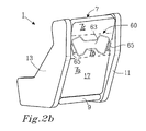
- Figures 2a and 2b are perspective views of the child seat 1 seen from the front and from behind.
- the back portion comprises a lower back region 7a, a shoulder region 7b and a head region 7c.
- the shoulder region 7b is located at a height corresponding essentially to the shoulders of a child when seated in the child seat 1.
- the head region 7c corresponds to the head of a child when seated in the child seat 1. Since the child seat may be used by children of varying size, the shoulder region 7b extends in the height direction from an infant size to a height corresponding to the largest child, for which the child seat is intended, e.g. 4 years. If the child seat is used by a small child, not only its shoulders, but also its head may be located at least partly at the shoulder region.
- a force-receiving assembly 60 is located at the shoulder region 7b and comprises a first portion 61 at the first side 15 of the back portion 7, and a second portion 63 at the second side 17 of the back portion 7.
- the first portion 61 provides an anchor point for the shoulder portion 23, 25 of the safety belt.
- the force-receiving assembly 60 is further adapted also to receive the child seat fixation means.
- loops 65 are provided in the first 61 and second portion 63, through which the belts 33, 35, illustrated in Figure 1 , may pass.
- the force-receiving assembly 60 here the first portion 61 and the second portion 63, is made of a more rigid material than a main portion of the back portion 7.
- the main portion of the back portion 7 may for example be made of fabric or plastic, which will be described in more detail below in conjunction with Figure 3 .
- the first 61 and second 63 portion may be made of a rigid plastic or metal.
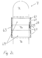
- the first 61 and second portion 63 may be directly connected to each other through the back portion 7, or as in the illustrated embodiment, be connected to each other by means of at least one connection belt 69 as seen in Figure 2c .
- the connection belt 69 helps to transfer forces of the shoulder portions 23, 25 via the first portion 61 to the second portion 63 of the force-receiving assembly 60.
- connection belt 69 may extend around the circumference of the back portion 7.
- separate connection belts 69 may be used at each lateral side of back portion 7.
- the first portion 61 and second portion 63 may be one and the same unit, which in that case preferably is located such that it is available both from the first 15 and second side 17 of the back portion 7 in order to be able to anchor both the child seat fixation means, e.g. belts 33, 35, and the shoulder portions 23, 25 of the safety belt.
- the shoulder portions 23, 25 of the safety belt may be attached at a selectable height, here achieved by providing a plurality of slots 67 at various heights in the first portion 61.
- the force-receiving assembly may provide vertical adjustability by being slidable or by providing a plurality of connection points.
- a child seat according to the invention may be suitable for children up to 4 years.
- the part of the safety belt 21 forming the shoulder portion 23, 25 may pass through one of the slots 67, through an opening in the back portion 7 to the second portion 63 of the force-receiving assembly 60, continue at the second side 17 of the back portion 7, return through another opening in the back portion 7 and form one of the waist portions 27, 29 of the safety belt 21.
- a portion of that belt may in that case extend along the first portion 61 of the force-receiving assembly 60, from a position corresponding to the left shoulder of the child to a position corresponding to the right shoulder of the child.
- the child seat fixation means may form a part of the child seat 1, for example by being sewn, stitched, bonded or glued to the child seat 1 at least at one location, at the end or somewhere mid-span, such that the child seat fixation means and the child seat 1 form one unit.
- the child seat fixation means may also be connected to the child seat by passing through loops 65, as in Figure 2a and b, or by a hook or a latch.
- the child seat fixation means is attached to the second portion 63 of the force-receiving assembly.
- the child seat fixation means is detachably attachable to the vehicle interior.
- the child seat fixation means may instead form separate units, such as loose belts or straps, which may be attached to the vehicle interior and to the child seat 1, respectively.
- the child seat 1 may be assembled from multiple inflatable air chambers.
- Figure 3 illustrates the back portion 7, the squab portion 9 and the side portions 11, 13 as separate air chambers.
- two or more of the portions 7, 9, 11, 13 may form a common air chamber.
- the back portion 7 and squab portion 9 may be formed as an integral unit.
- the air chambers are interconnectable such that they form a continuous inflatable volume requiring only a single port for inflation and deflation.
- Interconnection between the one or more inflatable air chambers forming the portions 7, 9, 11, 13 may for example be achieved by using hollow plastic grommets 71, 73 as illustrated in Figure 3 .
- These grommets 71, 73 are attached to each air chamber in a manner that allows the grommets 71, 73 located opposite each other to snap fit and/or glue together to provide a continuous inflatable volume between the air chambers.
- the grommets 71, 73 should preferably be thin walled, such that they are flexible with the fabric of the air chambers. Attachment surfaces for bonding to the fabric should preferably be provided with ridges or similar structural elements in order to facilitate bonding between the grommets 71, 73 and the fabric.
- the grommets 71, 73 are intended to be paired to fit together to provide an unobstructed air-tight passage between the air chambers. Once the child seat 1 has been assembled, the grommets 71, 73 are essentially invisible to an external viewer. A series of air chambers thus connected require only a single port for inflation and deflation.
- the portions 7, 9, 11, 13 of the child seat 1 may be configured as one common air chamber, thereby being possible to inflate through one single port. Yet another alternative would be to use separate ports for the different portions 7, 9, 11, 13 of the child seat 1.
- the entire inflatable child seat 1 can be inflated and deflated through a single port or air valve.
- the pressure through the inflatable child seat 1 places the structure in an operating mode where it becomes a substantially rigid structure due to the air pressure. Then, when it is deflated, the child seat can be folded into a rather compact package for easy stowage in the vehicle.
- the chambers may be constructed out of a non-permeable fabric that comprises means for limiting a maximal separation between at least two non-permeable fabric surfaces when inflated. It is appropriate to use what is commonly called a "drop-stitch fabric” or “drop-stitch structure” as the means for limiting a maximal separation in order to provide the basic structure of the inflatable child seat 1.
- the "drop-stitch fabric” 75 comprises upper and lower non-permeable fabric layers 75a and 75b, with a core section positioned between, and connected to, the upper and lower non-permeable fabric layers 75a and 75b.
- This core section comprises a plurality of individual stitches, e.g. threads or cords 77, which have upper and lower end portions which connect to, respectively, the upper and lower non-permeable fabric layers 75a and 75b.
- the stitching 77 thus limits a maximal separation between the non-permeable surfaces 75a and 75b of the inflatable drop-stitch fabric 75 when inflated.
- the air chamber is constructed out of drop-stitch fabric 75 which comprises two flexible non-permeable surfaces 75a and 75b that are spanned by a plurality of stitches 77 of fixed lengths.
- the stitching 77 thus, as stated above, maintains a constant separation between the non-permeable surfaces 75a and 75b when inflated, resulting in an air chamber that has essentially flat surfaces that do not curve outwards.
- the main portion of the child seat is made of a light-weight material. Besides the main portion, there may also be details made of other materials such as the connection members described below in conjunction with Figure 8a and b. Examples of suitable light-weight materials are extruded foam, such as polystyrene, and the above-mentioned air chambers. It would also be possible to fill the chambers with another gas, but air is practical since it is readily available.
- the child seat may also be partly inflatable, for example by having inflatable side portions and non-inflatable back portion and squab portion made of another light-weight material.
- the purpose of the light-weight material is to provide a child seat, which weighs less than the conventional child seats comprising a plastic shell.
- the child seat according to the invention may thus weigh 10% less, preferably 20% and most preferably 30%, and in some cases up to 50%, less than a conventional child seat of equal size.
- the main portion of the back portion 7 is constituted by a light-weight material, it is the force-receiving assembly 60 that provides strength and durability needed for anchoring of the child seat fixation means 33, 35 and the shoulder portions 23, 25 of the safety belt.
- the first 61 and second 63 portions of the force-receiving assembly are therefore made of a more rigid material than the main portion of the back portion 7. They may suitably be made of metal or a strong plastic. The force-receiving assembly is thus made of a more rigid material than the main portion of the back portion.
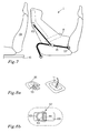
- Figure 5 illustrates a number of alternative child seat fixation means. One or more of them may be used at the same time, also together with the child seat fixation means in the form of the belts 33, 35 described in conjunction with Figure 1 .
- a front belt 79 extends from the second portion 63 of the force-receiving assembly to the rail 41 or any other suitable fix point on the vehicle floor. Suitably, a second front belt (not illustrated) is used, connecting to the rail 43.
- a headrest strap 83 passes around the back rest or a head rest of the front seat 19.
- An ISO-fix strap 81 connects the child seat 1 to the ISO fix attachment 57.
- the other end of the ISO-fix strap 81 may be attached to a rear end 85 of the child seat or to a reinforcement strap/belt as described below in conjunction with Figure 9 .
- a second ISO-fix strap is used, connecting to the other ISO fix attachment 59.
- One or more rear straps 87 may connect the back portion 7 or side portions 11, 13 to the back seat. They may for example pass around a head rest 88.
- At least one rigid subframe may be used as illustrated in Figures 6 and 7 .
- the rigid subframe extends between the second portion 63 of the force-receiving assembly and one or both of the rails 41, 43 or any other suitable fix point on the vehicle floor in the form of a leg 89.
- the subframe 89 may have a telescoping function in order to adapt the length of it to the vehicle, in which the child seat 1 is to be mounted.
- the leg 89 may be attached to the child seat 1 via a pivotable joint, which may be located at a supplementary bracket, which is mounted at the second portion 63.
- the rigid subframe comprises a docking unit 91 located on the back seat 5 and preferably attached to the ISO fix attachments 57, 59 and to the vehicle floor.
- the docking unit 91 is connected to the child seat 1 via the second portion 63 of the force-receiving assembly, e.g. via a pivotable joint. Since the subframe, e.g. the leg 89 or the docking unit 91, is rigid, it may transfer forces to and from the child seat.
- Figure 8a and 8b show in detail how belts and straps, such as the ones used as child seat fixation means and safety belts, may be attached to the child seat by means of connection members 93, 97. Such attachments are for example suitable when using a child seat comprising inflatable air chambers as illustrated above in Figures 3 and 4 .
- Figure 8a shows a metal loop 93 moulded as reinforcement into a plastic attachment 95. This is suitable for the attachment of a belt, as shown to the right in the figure.
- Figure 8b illustrates a double D-ring 97, which may be used to transfer forces from one belt/strap to another without passing through the inflatable air chamber.
- the double D-ring comprises a first part 99, which is attached to the surface of the child seat, a second part 101, whereto one belt strap may be attached, and a third part 103 whereto another belt strap may be attached. Thereby a force may be transferred from one belt/strap to another without the belts passing through the inflatable air chamber.
- the double D-ring may be attached to the child seat by a patch 105, which may be sewn, stitched, bonded or glued to the child seat. It is also possible to use a normal, i.e. single, D-ring for connecting one belt to the surface of the child seat.
- Reinforcement belt/straps may be used to reinforce the child seat 1.
- One or more reinforcement belt/strap may be used, as exemplified by two belts in Figure 9 .
- the reinforcement belt/straps may run along the inside and/or the outside of the child seat. If a cover is used, they may extend beneath the coves, such that they are externally invisible, Normally, there is a similar configuration of reinforcement belt/straps on each side portion 11, 13 of the child seat 1. In a configuration like the one illustrated in Figure 9 , a first reinforcement belt 107 may run along the outside of the child seat 1, and a second 109 along the inside of the child seat 1.
- the reinforcement belt 107, 109 may envelope the back of the child seat 1, as in Figure 9 , or may be divided into separate segments at each side of the child seat.
- the reinforcement belt may be attached to the child seat by means of a loop, a D-ring or a double D-ring.
- the reinforcement belt is suitably arranged inside of the cover. Further, the reinforcement belt may also be attached to the ISO fix attachments 57, 59, thereby further securing the child seat.
- a flexible panel 111 for example made of a fabric or a net, extends from the child seat 1 in the direction towards the back seat, where a strap 113 may connect the panel 111 to the head rest 88.
- the flexible panel 111 may be made in one piece, which envelops the back of the child seat 1, or as two separate side pieces.
- a kit of parts may, further to the inflatable child seat 1, comprise an inflator in order to facilitate inflation of the inflatable child seat.
- the inflator may be a manual or motorized air pump.
- the inflator may be integrated into the child seat, an optional rigid subframe, or remain a discrete device for which storage is provided within the child seat structure or its cover.
- the inflator can also serve as a deflator to evacuate air from the air chambers in order to allow the child seat to be folded into a more compact volume when not in use.
- a battery-powered electronic sensor may be used to monitor air pressure.
- the motorized inflator and sensor may be powered by a 12V vehicle power outlet or by a built-in battery. The air pressure and battery state of charge may be continuously monitored by the electronic system and warnings may be issued as required.
Landscapes
- Engineering & Computer Science (AREA)
- Health & Medical Sciences (AREA)
- Child & Adolescent Psychology (AREA)
- General Health & Medical Sciences (AREA)
- Aviation & Aerospace Engineering (AREA)
- Transportation (AREA)
- Mechanical Engineering (AREA)
- Seats For Vehicles (AREA)
Claims (15)
- Ein Kindersitz (1) für eine Nutzung entgegen der Fahrtrichtung in einem Fahrzeug (3), wobei der Kindersitz (1) einen Rückenbereich (7) und einen Sitzflächenbereich (9) umfasst, wobei der Rückenbereich (7) eine erste Seite (15) umfasst, die daran angepasst ist, den Rücken eines Kindes zu stützen, wenn das Kind in dem Kindersitz (1) sitzt, und eine zweite Seite (17) umfasst, die der ersten Seite (15) entgegen gesetzt ist, wobei der Rückenbereich (7) einen unteren Rückenbereich (7a), einen Schulterbereich (7b) und einen Kopfbereich (7c) umfasst, wobei der Sitzflächenbereich (9) daran angepasst ist, das Gesäß eines Kindes zu stützen, wenn das Kind in dem Kindersitz (1) sitzt, und der Kindersitz (1) des Weiteren eine Kindersitz-Sicherheitsgurtanordnung (21) umfasst, um das Kind zu sichern, das in dem Kindersitz (1) sitzen soll,
dadurch gekennzeichnet, dass der Rückenbereich (7) eine Kraft aufnehmende Anordnung (60) umfasst, die an dem Schulterbereich (7b) angeordnet ist, wobei die Kraft aufnehmende Anordnung (60) aus einem steiferen Material als der Hauptteil des Rückenbereiches (7) besteht, während jener Hauptteil aus einem Material von geringem Gewicht besteht;
die Kraft aufnehmende Anordnung (60) einen ersten Bereich (61) umfasst, welcher an der ersten Seite (15) des Rückenbereiches (7) angeordnet ist und einen Verankerungspunkt für einen Schulterabschnitt (23, 25) der Kindersitz-Sicherheitsgurtanordnung (21) bietet; und
die Kraft aufnehmende Anordnung (60) des Weiteren einen zweiten Bereich (63) umfasst, welcher an der zweiten Seite (17) des Rückenbereiches (7) angeordnet ist und einen Verankerungspunkt für ein Kindersitz-Befestigungsmittel (33, 35, 79, 83, 89, 91) bietet. - Kindersitz (1) nach Anspruch 1, worin ein Ende des Schulterabschnitts (23, 25) der Kindersitz-Sicherheitsgurtanordnung (21) an dem ersten Bereich (61) der Kraft aufnehmenden Anordnung (60) angebracht ist.
- Kindersitz (1) nach einem der vorangehenden Ansprüche, worin die Kraft aufnehmende Anordnung (60) Mittel zur Verankerung des Schulterbereiches (23, 25) an einem auswählbaren Abstand von dem Sitzfiächenbereich (9) umfasst.
- Kindersitz (1) nach einem der vorangehenden Ansprüche, worin der erste Abschnitt (61) und der zweite Abschnitt (63) der Kraft aufnehmenden Anordnung (60) durch einen Verbindungsgurt (69) oder ein Band miteinander verbunden sind.
- Kindersitz (1) nach einem der vorangehenden Ansprüche, worin das Kindersitz-Befestigungsmittel (33, 35) einen Gurt oder ein Band umfasst, welcher oder welches durch den ersten und den zweiten Abschnitt (63) der Kraft aufnehmenden Anordnung (60) verläuft.
- Kindersitz (1) nach einem der vorangehenden Ansprüche, worin das Kindersitz-Befestigungsmittel (33, 35, 79, 83, 89, 91) mit einer Schlaufe, einem Haken und / oder einem Riegel zur Befestigung an einem Fahrzeugsitz, Boden oder Innenraum versehen ist.
- Kindersitz (1) nach einem der vorangehenden Ansprüche, worin der Kindersitz (1) mindestens eine, zumindest teilweise aufblasbare, Luftkammer umfasst.
- Kindersitz (1) nach Anspruch 7, worin der Rückenbereich (7) und der Sitzflächenbereich (9) mindestens eine Luftkammer bilden;
der Kindersitz (1) des Weiteren Seitenbereiche (11, 13) umfasst, welche daran angepasst sind, an der entsprechenden seitlichen Seite des Rückenbereiches (7) und des Sitzflächenbereichs (9) angeordnet zu werden, wenn der Kindersitz (1) aufgeblasen ist, wobei die Seitenbereiche (11, 13) auch zumindest teilweise aufblasbare Luftkammern bilden;
die Luftkammern des Rückenbereichs (7), des Sitzflächenbereichs (9) und der Seitenabschnitte (11, 13) miteinander so verbunden werden können, dass sie ein durchgängiges, aufblasbares Volumen bilden. - Kindersitz (1) nach Anspruch 7 oder 8, worin die Luftkammer aus einem gasundurchlässigen Stoff (75) hergestellt ist und eingrenzende Mittel (77) umfasst, um einen maximalen Abstand zwischen mindestens zwei gasundurchlässigen Stoffoberflächen (75a, 75b) einzugrenzen, wobei die eingrenzenden Mittel (77) zum Beispiel aus einem Drop-Stitch-Stoff hergestellt sein können.
- Kindersitz (1) nach einem der vorangehenden Ansprüche, worin der Kindersitz (1) des Weiteren verbindende Teile (93, 97), zum Verbinden eines Gurtes oder eines Bandes mit dem Kindersitz (1) umfasst, wobei die verbindenden Teile (93, 97) an den Kindersitz (1) genäht, gesteppt, geschweißt und / oder geklebt sein können.
- Kindersitz (1) nach einem der vorangehenden Ansprüche, worin der Kindersitz (1) durch mindestens einen Verstärkungsgurt oder ein Verstärkungsband (107, 109) verstärkt wird, wobei sich der Verstärkungsgurt oder das Verstärkungsband (107, 109) entlang einer Oberfläche des Kindersitzes (1) erstreckt.
- Kindersitz (1) nach einem der vorangehenden Ansprüche, worin der Kindersitz (1) des Weiteren eine flexible Tafel (111) umfasst, welche daran angepasst ist, sich von dem Kindersitz (1), wenn dieser montiert ist, entlang einer entsprechenden seitlichen Seite des Kindersitzes (1) zu einem Verbindungspunkt an Boden oder Innenraum des Fahrzeugs hin zu erstrecken.
- Eine Kindersitzanordnung umfassend:- einen Kindersitz (1) nach einem der vorangehenden Ansprüche- mindestens einen steifen Unterrahmen (89, 91),wobei der Kindersitz (1) für das Befestigen an mindestens einem steifen Unterrahmen (89, 91) ausgelegt ist, und wobei der mindestens eine steife Unterrahmen (89, 91) dafür ausgelegt ist, an einem Boden oder Innenraum eines Fahrzeugs befestigt zu werden, so dass Kräfte zwischen dem Kindersitz (1) und dem Boden oder Innenraum des Fahrzeugs hin und her geleitet werden können.
- Ein Satz von Teilen, umfassend einen Kindersitz (1) nach einem der Ansprüche 7 bis 13 und eine Pumpe zum Aufblasen des Kindersitzes (1), wobei die Pumpe in den Kindersitz (1) eingebaut ist.
- Ein Fahrzeug (3), umfassend einen Kindersitz (1) nach einem der Ansprüche 1 bis 12, eine Kindersitzanordnung nach Anspruch 13 oder einen Satz von Teilen nach Anspruch 14, worin der Kindersitz (1) in einer der Fahrtrichtung entgegen gesetzten Position auf einem Rücksitz (5) des Fahrzeuges (3) installiert werden kann, so dass das Befestigen des Kindersitzes (1) mittels des Kindersitz-Befestigungsmittels (33, 35, 79, 83, 89, 91) erfolgt, welches direkt an die Fahrzeugkarosserie oder den Fahrzeuginnenraum, zum Beispiel durch einen ISOfix Punkt, angeschlossen ist.
Priority Applications (3)
| Application Number | Priority Date | Filing Date | Title |
|---|---|---|---|
| EP11173949.6A EP2546096B1 (de) | 2011-07-14 | 2011-07-14 | Kindersitz |
| US13/494,306 US8672403B2 (en) | 2011-07-14 | 2012-06-12 | Child seat |
| CN201210246610.0A CN102874139B (zh) | 2011-07-14 | 2012-07-16 | 儿童座椅、儿童座椅装置、成套部件及车辆 |
Applications Claiming Priority (1)
| Application Number | Priority Date | Filing Date | Title |
|---|---|---|---|
| EP11173949.6A EP2546096B1 (de) | 2011-07-14 | 2011-07-14 | Kindersitz |
Publications (2)
| Publication Number | Publication Date |
|---|---|
| EP2546096A1 EP2546096A1 (de) | 2013-01-16 |
| EP2546096B1 true EP2546096B1 (de) | 2013-09-11 |
Family
ID=44800924
Family Applications (1)
| Application Number | Title | Priority Date | Filing Date |
|---|---|---|---|
| EP11173949.6A Not-in-force EP2546096B1 (de) | 2011-07-14 | 2011-07-14 | Kindersitz |
Country Status (3)
| Country | Link |
|---|---|
| US (1) | US8672403B2 (de) |
| EP (1) | EP2546096B1 (de) |
| CN (1) | CN102874139B (de) |
Cited By (2)
| Publication number | Priority date | Publication date | Assignee | Title |
|---|---|---|---|---|
| EP2949240A1 (de) * | 2014-05-27 | 2015-12-02 | Volvo Car Corporation | Kindertransportvorrichtung |
| EP3088242A1 (de) | 2015-04-28 | 2016-11-02 | Volvo Car Corporation | Trägeranordnung für einen kindersitz |
Families Citing this family (26)
| Publication number | Priority date | Publication date | Assignee | Title |
|---|---|---|---|---|
| GB0905831D0 (en) * | 2009-04-03 | 2009-05-20 | Kelly Grainne | Bubblegum inflatable child booster seat for cars |
| US8340730B2 (en) | 2010-05-11 | 2012-12-25 | George Allen Pallotta | System and method for safely blocking mobile communications usages |
| CN103140373B (zh) * | 2010-09-14 | 2016-05-25 | 赛贝克斯工业技术有限公司 | 儿童座椅 |
| WO2012135894A1 (en) * | 2011-04-04 | 2012-10-11 | Oates Jayson Wayne | Inflatable car seat with integral air pump |
| US8950809B2 (en) * | 2011-10-06 | 2015-02-10 | Thorley Industries Llc | Child restraint system with user interface |
| US9751433B2 (en) | 2011-10-06 | 2017-09-05 | Thorley Industries Llc | Child restraint system with user interface |
| US10220734B2 (en) | 2013-03-05 | 2019-03-05 | Pidyon Controls Inc. | Car seat |
| US9487110B2 (en) * | 2014-03-05 | 2016-11-08 | Pidyon Controls Inc. | Car seat |
| US9254067B2 (en) * | 2013-03-14 | 2016-02-09 | Galia YAARI | Infant feeding and bathing system |
| JP5673974B2 (ja) * | 2013-03-25 | 2015-02-18 | 三菱自動車工業株式会社 | アンカーの取付け構造 |
| US9714002B2 (en) * | 2013-12-10 | 2017-07-25 | Wonderland Nurserygoods Company Limited | Safety belt buffering mechanism and related vehicle safety chair |
| US9393886B2 (en) * | 2014-02-28 | 2016-07-19 | Diono, Llc | Safety seat/booster seat harness pad |
| MX2017013976A (es) | 2015-05-12 | 2018-03-14 | Pidyon Controls Inc | Asiento para automovil y sistema de conexion. |
| TWI564189B (zh) * | 2015-08-11 | 2017-01-01 | 國立清華大學 | 車用安全座椅 |
| TWI551482B (zh) * | 2015-08-11 | 2016-10-01 | 國立清華大學 | 車用安全座椅 |
| CN105480126A (zh) * | 2015-12-04 | 2016-04-13 | 唐国云 | 一种汽车内置气囊式座椅 |
| WO2017132379A1 (en) * | 2016-01-29 | 2017-08-03 | David Reay | Oxidizing disinfectant formulation and methods of use |
| AT518172B1 (de) * | 2016-07-27 | 2017-08-15 | Atumkid Gmbh | Kindersitz |
| US10596929B2 (en) * | 2017-09-22 | 2020-03-24 | Jodi L. Houin | Child restraint system including harness and adjustment mechanism |
| DE102017219088B4 (de) * | 2017-10-25 | 2021-06-02 | Ford Global Technologies, Llc | Kraftfahrzeugsitz mit integriertem Kindersitz |
| CN108045340A (zh) * | 2018-01-23 | 2018-05-18 | 上海沃雨电子科技有限公司 | 儿童安全座椅的安全带换挡结构及其制作与换挡方法 |
| US11273790B2 (en) | 2018-03-06 | 2022-03-15 | Shield Restraint Systems, Inc. | Height adjusters with anti-cinch features for occupant restraint systems |
| US10953847B2 (en) | 2018-03-06 | 2021-03-23 | Shield Restraint Systems | Height adjusters with anti-cinch features for occupant restraint systems |
| DE102019111203A1 (de) * | 2019-04-30 | 2020-11-05 | Erwin Hymer Group Se | Fahrzeug mit drop-stitch Möbel |
| US11976487B2 (en) | 2020-09-22 | 2024-05-07 | Flated Llc | Inflatable cargo carrier for a vehicle roof |
| CN114274850B (zh) * | 2021-12-28 | 2023-04-28 | 东莞金旺儿童用品有限公司 | 一种靠背结构及座椅 |
Family Cites Families (44)
| Publication number | Priority date | Publication date | Assignee | Title |
|---|---|---|---|---|
| US4067608A (en) * | 1975-11-26 | 1978-01-10 | Wimmersperg Heinrich F Von | Child safety restraint |
| US4480870A (en) * | 1981-10-13 | 1984-11-06 | Wimmersperg Heinrich F Von | Infant restraint for vehicles |
| US4640545A (en) * | 1985-05-13 | 1987-02-03 | Wimmersperg Heinrich F Von | Lock for vehicle infant restraint |
| DE4230879C2 (de) * | 1991-09-30 | 2000-10-19 | Volkswagen Ag | Kindersitzanordnung mit einem auf einen Fahrzeugsitz aufsetzbaren Kindersitz |
| KR100279488B1 (ko) * | 1992-05-13 | 2001-02-01 | 콘 게리 엠 | 아동용 통합 좌석 모듈 |
| GB9306977D0 (en) * | 1993-04-03 | 1993-05-26 | Britax Excelsior | Child saftey seat |
| GB9307446D0 (en) * | 1993-04-08 | 1993-06-02 | Britax Excelsior | Child safety seat |
| AUPM715494A0 (en) * | 1994-08-01 | 1994-08-18 | Britax Child-Care Products Pty Ltd | Safety seat tether strap |
| US5685603A (en) * | 1996-03-05 | 1997-11-11 | Trw Vehicle Safety Systems Inc. | Apparatus with a child seat and an energy absorption mechanism |
| FR2750371B1 (fr) * | 1996-06-28 | 1998-08-21 | Ampafrance | Siege pour enfant destine a etre fixe sur un siege de vehicule au moyen d'une ceinture de securite |
| US5941600A (en) * | 1996-11-14 | 1999-08-24 | Chrysler Corporation | Method and apparatus for mounting articles to a vehicle floor |
| US5820215A (en) * | 1997-04-29 | 1998-10-13 | Dreisbach; Kurt R. | Child safety seat adapter |
| DE19732385C2 (de) * | 1997-07-25 | 2000-03-09 | Opel Adam Ag | Befestigung für einen Kindersitz auf dem Rücksitz eines Kraftfahrzeuges |
| US6237999B1 (en) * | 1999-08-24 | 2001-05-29 | Donald A. Hobson | Child car seat |
| JP4472127B2 (ja) * | 2000-06-28 | 2010-06-02 | コンビ株式会社 | チャイルドシート |
| AUPQ845100A0 (en) * | 2000-06-30 | 2000-07-27 | Britax Child-Care Products Pty Ltd | Attachment of child shoulder harness to a booster seat |
| US6592183B2 (en) * | 2001-02-16 | 2003-07-15 | Cosco Management, Inc. | Vehicle anchor system for juvenile vehicle seat |
| US6669302B2 (en) * | 2001-05-08 | 2003-12-30 | Graco Children's Products Inc. | Seat belt position adjusting arrangement for a vehicle seat |
| US6817665B2 (en) * | 2001-07-26 | 2004-11-16 | Graco Children's Products Inc. | Seat base with load leg |
| EP1285810B1 (de) * | 2001-08-21 | 2007-11-07 | Britax Excelsior Limited | Kindersicherheitssitz |
| JP4348417B2 (ja) * | 2002-07-08 | 2009-10-21 | アップリカ・チルドレンズプロダクツ株式会社 | 自動車用子供座席 |
| JP4090820B2 (ja) * | 2002-08-29 | 2008-05-28 | 本田技研工業株式会社 | チャイルドシートの取付構造 |
| CA2449390A1 (en) * | 2002-11-14 | 2004-05-14 | Cosco Management, Inc. | Shock absorber for juvenile vehicle seat tether |
| WO2004091964A1 (de) * | 2003-04-15 | 2004-10-28 | Prospective Concepts Ag | Kindersitz für ein fahrzeug |
| US7233239B2 (en) * | 2003-11-04 | 2007-06-19 | Ford Global Technologies, Llc | Method and apparatus for detecting improper installation of child seat in a vehicle |
| US20080303321A1 (en) * | 2004-05-08 | 2008-12-11 | Britax Excelsior Limited | Base for a Child Safety Support |
| NL1026385C2 (nl) * | 2004-06-10 | 2005-12-14 | Maxi Miliaan Bv | Kindervoertuigstoel alsmede frame geschikt voor een dergelijke kindervoertuigstoel. |
| ES2246722B1 (es) | 2004-08-12 | 2007-05-01 | Benito Mondragon Martinez | Silla inflable para bebes adaptable a la parte posterior del asiento delantero adyacente al del conductor de un automovil. |
| GB0420414D0 (en) * | 2004-09-14 | 2004-10-20 | Barker Derrick | Child car seat |
| NL1028788C2 (nl) * | 2005-04-18 | 2006-10-20 | Maxi Miliaan Bv | Onderstel alsmede kindervoertuigstoel voorzien van een dergelijk onderstel. |
| US7472952B2 (en) * | 2005-09-09 | 2009-01-06 | Britax Child Safety, Inc. | Safety seat |
| DE102006034557A1 (de) * | 2005-11-30 | 2007-08-02 | Cybex Industrial Ltd. | Drehbarer Kindersitz für Kraftfahrzeuge |
| DE102006033849B4 (de) * | 2005-11-30 | 2021-05-06 | Cybex Gmbh | Befestigungssystem für einen Kraftfahrzeug-Kindersitz |
| US20080012401A1 (en) * | 2006-05-09 | 2008-01-17 | Britax Child Safety, Inc. | Energy absorbing tether for child safety seat |
| ES1063434Y (es) * | 2006-07-14 | 2007-01-16 | Jane Sa | Base para el acoplamiento de asientos infantiles en automoviles |
| CN2928580Y (zh) * | 2006-08-02 | 2007-08-01 | 明门实业股份有限公司 | 儿童汽车安全座椅的支撑装置 |
| EP1970247A1 (de) * | 2007-03-15 | 2008-09-17 | Team-Tex | Vorrichtung zum Anbringen eines Kindersitzes in einem Auto und Kindersitz |
| US20100052384A1 (en) * | 2008-08-26 | 2010-03-04 | Link Treasure Limited | Child safety seat with a transverse engaging base |
| NO329442B1 (no) * | 2008-09-08 | 2010-10-18 | Hts Hans Torgersen & Sonn As | Anordning ved et bilbarnesete |
| AU2010246523A1 (en) * | 2009-11-30 | 2011-06-16 | Hbg Ip Holding Pty Ltd | A child safety seat for a vehicle |
| CN102985286B (zh) * | 2010-03-24 | 2015-12-16 | 谛欧诺有限责任公司 | 倾斜骑倒式儿童座椅 |
| US9039083B2 (en) * | 2010-03-24 | 2015-05-26 | Diono, Llc | Crash indication system for a reclining ride down child seat |
| US8585138B2 (en) * | 2010-10-26 | 2013-11-19 | Cosco Management, Inc. | Rigidifying system for single shell juvenile vehicle seat |
| US8496293B2 (en) * | 2010-12-13 | 2013-07-30 | Cosco Management, Inc. | Energy-dissipation system for juvenile vehicle seat |
-
2011
- 2011-07-14 EP EP11173949.6A patent/EP2546096B1/de not_active Not-in-force
-
2012
- 2012-06-12 US US13/494,306 patent/US8672403B2/en not_active Expired - Fee Related
- 2012-07-16 CN CN201210246610.0A patent/CN102874139B/zh active Active
Cited By (3)
| Publication number | Priority date | Publication date | Assignee | Title |
|---|---|---|---|---|
| EP2949240A1 (de) * | 2014-05-27 | 2015-12-02 | Volvo Car Corporation | Kindertransportvorrichtung |
| US9730526B2 (en) | 2014-05-27 | 2017-08-15 | Volvo Car Corporation | Child transport device |
| EP3088242A1 (de) | 2015-04-28 | 2016-11-02 | Volvo Car Corporation | Trägeranordnung für einen kindersitz |
Also Published As
| Publication number | Publication date |
|---|---|
| CN102874139A (zh) | 2013-01-16 |
| CN102874139B (zh) | 2016-09-07 |
| EP2546096A1 (de) | 2013-01-16 |
| US20130015690A1 (en) | 2013-01-17 |
| US8672403B2 (en) | 2014-03-18 |
Similar Documents
| Publication | Publication Date | Title |
|---|---|---|
| US8672403B2 (en) | Child seat | |
| US8579372B2 (en) | Rearward facing inflatable child seat | |
| EP2173579B1 (de) | Kindersitz oder sitzerhöhung für ein fahrzeug | |
| US7413249B2 (en) | Child seat for a vehicle | |
| US8528983B2 (en) | Inflatable child airplane seat | |
| CN103619219B (zh) | 旅行头枕 | |
| KR101348542B1 (ko) | 유아시트 겸용 자동차 시트커버 | |
| CN205706573U (zh) | 具有气囊的侧衬垫组件 | |
| US5029928A (en) | Pickup truck bed seat | |
| EP1526034A1 (de) | Sicherheitssitz mit verstellarer Kopfstütze. | |
| US20220250522A1 (en) | Support System Providing a Supporting Surface for Rest in a Vehicle | |
| EP2484549A1 (de) | Kindersitz | |
| US20180079329A1 (en) | Vehicular Seating Assembly, System and Method | |
| JP6528157B2 (ja) | サイドエアバッグモジュール及び組立品 | |
| CN109278604A (zh) | 一种推车式安全座椅及其转换为背包或汽车安全座椅的方法 | |
| WO2011145087A1 (en) | Headrest | |
| US9730526B2 (en) | Child transport device | |
| EP3626517B1 (de) | Kindersitzstrukturelement und mehrgruppenkinderautositz | |
| CN216723867U (zh) | 一种背靠装置及其充气调节结构 | |
| CN112977182B (zh) | 具有罩片的座椅组件 | |
| KR101079138B1 (ko) | 높낮이 조절이 가능한 의자용 간이 다목적 쿠션 장치 | |
| US20110140495A1 (en) | Head and Neck Support Apparatus and Method | |
| CN204623398U (zh) | 用于交通工具的垫组件 | |
| CZ302787B6 (cs) | Nafukovací detské zádržné zarízení | |
| CN119546505A (zh) | 多用途挂车及将可移除的座椅固定到多用途挂车的方法 |
Legal Events
| Date | Code | Title | Description |
|---|---|---|---|
| PUAI | Public reference made under article 153(3) epc to a published international application that has entered the european phase |
Free format text: ORIGINAL CODE: 0009012 |
|
| AK | Designated contracting states |
Kind code of ref document: A1 Designated state(s): AL AT BE BG CH CY CZ DE DK EE ES FI FR GB GR HR HU IE IS IT LI LT LU LV MC MK MT NL NO PL PT RO RS SE SI SK SM TR |
|
| AX | Request for extension of the european patent |
Extension state: BA ME |
|
| 17P | Request for examination filed |
Effective date: 20130319 |
|
| GRAP | Despatch of communication of intention to grant a patent |
Free format text: ORIGINAL CODE: EPIDOSNIGR1 |
|
| INTG | Intention to grant announced |
Effective date: 20130516 |
|
| GRAS | Grant fee paid |
Free format text: ORIGINAL CODE: EPIDOSNIGR3 |
|
| GRAA | (expected) grant |
Free format text: ORIGINAL CODE: 0009210 |
|
| AK | Designated contracting states |
Kind code of ref document: B1 Designated state(s): AL AT BE BG CH CY CZ DE DK EE ES FI FR GB GR HR HU IE IS IT LI LT LU LV MC MK MT NL NO PL PT RO RS SE SI SK SM TR |
|
| REG | Reference to a national code |
Ref country code: GB Ref legal event code: FG4D |
|
| REG | Reference to a national code |
Ref country code: CH Ref legal event code: EP |
|
| REG | Reference to a national code |
Ref country code: AT Ref legal event code: REF Ref document number: 631428 Country of ref document: AT Kind code of ref document: T Effective date: 20130915 |
|
| REG | Reference to a national code |
Ref country code: IE Ref legal event code: FG4D |
|
| REG | Reference to a national code |
Ref country code: DE Ref legal event code: R096 Ref document number: 602011002994 Country of ref document: DE Effective date: 20131107 |
|
| REG | Reference to a national code |
Ref country code: SE Ref legal event code: TRGR |
|
| PG25 | Lapsed in a contracting state [announced via postgrant information from national office to epo] |
Ref country code: LT Free format text: LAPSE BECAUSE OF FAILURE TO SUBMIT A TRANSLATION OF THE DESCRIPTION OR TO PAY THE FEE WITHIN THE PRESCRIBED TIME-LIMIT Effective date: 20130911 Ref country code: NO Free format text: LAPSE BECAUSE OF FAILURE TO SUBMIT A TRANSLATION OF THE DESCRIPTION OR TO PAY THE FEE WITHIN THE PRESCRIBED TIME-LIMIT Effective date: 20131211 Ref country code: HR Free format text: LAPSE BECAUSE OF FAILURE TO SUBMIT A TRANSLATION OF THE DESCRIPTION OR TO PAY THE FEE WITHIN THE PRESCRIBED TIME-LIMIT Effective date: 20130911 Ref country code: CY Free format text: LAPSE BECAUSE OF FAILURE TO SUBMIT A TRANSLATION OF THE DESCRIPTION OR TO PAY THE FEE WITHIN THE PRESCRIBED TIME-LIMIT Effective date: 20130918 |
|
| REG | Reference to a national code |
Ref country code: NL Ref legal event code: VDEP Effective date: 20130911 |
|
| REG | Reference to a national code |
Ref country code: AT Ref legal event code: MK05 Ref document number: 631428 Country of ref document: AT Kind code of ref document: T Effective date: 20130911 |
|
| REG | Reference to a national code |
Ref country code: LT Ref legal event code: MG4D |
|
| PG25 | Lapsed in a contracting state [announced via postgrant information from national office to epo] |
Ref country code: GR Free format text: LAPSE BECAUSE OF FAILURE TO SUBMIT A TRANSLATION OF THE DESCRIPTION OR TO PAY THE FEE WITHIN THE PRESCRIBED TIME-LIMIT Effective date: 20131212 Ref country code: FI Free format text: LAPSE BECAUSE OF FAILURE TO SUBMIT A TRANSLATION OF THE DESCRIPTION OR TO PAY THE FEE WITHIN THE PRESCRIBED TIME-LIMIT Effective date: 20130911 Ref country code: LV Free format text: LAPSE BECAUSE OF FAILURE TO SUBMIT A TRANSLATION OF THE DESCRIPTION OR TO PAY THE FEE WITHIN THE PRESCRIBED TIME-LIMIT Effective date: 20130911 |
|
| PG25 | Lapsed in a contracting state [announced via postgrant information from national office to epo] |
Ref country code: CY Free format text: LAPSE BECAUSE OF FAILURE TO SUBMIT A TRANSLATION OF THE DESCRIPTION OR TO PAY THE FEE WITHIN THE PRESCRIBED TIME-LIMIT Effective date: 20130911 Ref country code: BE Free format text: LAPSE BECAUSE OF FAILURE TO SUBMIT A TRANSLATION OF THE DESCRIPTION OR TO PAY THE FEE WITHIN THE PRESCRIBED TIME-LIMIT Effective date: 20130911 |
|
| PG25 | Lapsed in a contracting state [announced via postgrant information from national office to epo] |
Ref country code: EE Free format text: LAPSE BECAUSE OF FAILURE TO SUBMIT A TRANSLATION OF THE DESCRIPTION OR TO PAY THE FEE WITHIN THE PRESCRIBED TIME-LIMIT Effective date: 20130911 Ref country code: CZ Free format text: LAPSE BECAUSE OF FAILURE TO SUBMIT A TRANSLATION OF THE DESCRIPTION OR TO PAY THE FEE WITHIN THE PRESCRIBED TIME-LIMIT Effective date: 20130911 Ref country code: IS Free format text: LAPSE BECAUSE OF FAILURE TO SUBMIT A TRANSLATION OF THE DESCRIPTION OR TO PAY THE FEE WITHIN THE PRESCRIBED TIME-LIMIT Effective date: 20140111 Ref country code: SK Free format text: LAPSE BECAUSE OF FAILURE TO SUBMIT A TRANSLATION OF THE DESCRIPTION OR TO PAY THE FEE WITHIN THE PRESCRIBED TIME-LIMIT Effective date: 20130911 Ref country code: RO Free format text: LAPSE BECAUSE OF FAILURE TO SUBMIT A TRANSLATION OF THE DESCRIPTION OR TO PAY THE FEE WITHIN THE PRESCRIBED TIME-LIMIT Effective date: 20130911 Ref country code: NL Free format text: LAPSE BECAUSE OF FAILURE TO SUBMIT A TRANSLATION OF THE DESCRIPTION OR TO PAY THE FEE WITHIN THE PRESCRIBED TIME-LIMIT Effective date: 20130911 |
|
| PG25 | Lapsed in a contracting state [announced via postgrant information from national office to epo] |
Ref country code: PL Free format text: LAPSE BECAUSE OF FAILURE TO SUBMIT A TRANSLATION OF THE DESCRIPTION OR TO PAY THE FEE WITHIN THE PRESCRIBED TIME-LIMIT Effective date: 20130911 Ref country code: AT Free format text: LAPSE BECAUSE OF FAILURE TO SUBMIT A TRANSLATION OF THE DESCRIPTION OR TO PAY THE FEE WITHIN THE PRESCRIBED TIME-LIMIT Effective date: 20130911 Ref country code: ES Free format text: LAPSE BECAUSE OF FAILURE TO SUBMIT A TRANSLATION OF THE DESCRIPTION OR TO PAY THE FEE WITHIN THE PRESCRIBED TIME-LIMIT Effective date: 20130911 |
|
| REG | Reference to a national code |
Ref country code: DE Ref legal event code: R097 Ref document number: 602011002994 Country of ref document: DE |
|
| PG25 | Lapsed in a contracting state [announced via postgrant information from national office to epo] |
Ref country code: PT Free format text: LAPSE BECAUSE OF FAILURE TO SUBMIT A TRANSLATION OF THE DESCRIPTION OR TO PAY THE FEE WITHIN THE PRESCRIBED TIME-LIMIT Effective date: 20140113 |
|
| PLBE | No opposition filed within time limit |
Free format text: ORIGINAL CODE: 0009261 |
|
| STAA | Information on the status of an ep patent application or granted ep patent |
Free format text: STATUS: NO OPPOSITION FILED WITHIN TIME LIMIT |
|
| 26N | No opposition filed |
Effective date: 20140612 |
|
| PG25 | Lapsed in a contracting state [announced via postgrant information from national office to epo] |
Ref country code: IT Free format text: LAPSE BECAUSE OF FAILURE TO SUBMIT A TRANSLATION OF THE DESCRIPTION OR TO PAY THE FEE WITHIN THE PRESCRIBED TIME-LIMIT Effective date: 20130911 |
|
| REG | Reference to a national code |
Ref country code: DE Ref legal event code: R097 Ref document number: 602011002994 Country of ref document: DE Effective date: 20140612 |
|
| PG25 | Lapsed in a contracting state [announced via postgrant information from national office to epo] |
Ref country code: DK Free format text: LAPSE BECAUSE OF FAILURE TO SUBMIT A TRANSLATION OF THE DESCRIPTION OR TO PAY THE FEE WITHIN THE PRESCRIBED TIME-LIMIT Effective date: 20130911 |
|
| PG25 | Lapsed in a contracting state [announced via postgrant information from national office to epo] |
Ref country code: LU Free format text: LAPSE BECAUSE OF FAILURE TO SUBMIT A TRANSLATION OF THE DESCRIPTION OR TO PAY THE FEE WITHIN THE PRESCRIBED TIME-LIMIT Effective date: 20140714 |
|
| REG | Reference to a national code |
Ref country code: CH Ref legal event code: PL |
|
| REG | Reference to a national code |
Ref country code: IE Ref legal event code: MM4A |
|
| REG | Reference to a national code |
Ref country code: FR Ref legal event code: ST Effective date: 20150331 |
|
| PG25 | Lapsed in a contracting state [announced via postgrant information from national office to epo] |
Ref country code: LI Free format text: LAPSE BECAUSE OF NON-PAYMENT OF DUE FEES Effective date: 20140731 Ref country code: CH Free format text: LAPSE BECAUSE OF NON-PAYMENT OF DUE FEES Effective date: 20140731 |
|
| PG25 | Lapsed in a contracting state [announced via postgrant information from national office to epo] |
Ref country code: FR Free format text: LAPSE BECAUSE OF NON-PAYMENT OF DUE FEES Effective date: 20140731 |
|
| PG25 | Lapsed in a contracting state [announced via postgrant information from national office to epo] |
Ref country code: IE Free format text: LAPSE BECAUSE OF NON-PAYMENT OF DUE FEES Effective date: 20140714 |
|
| PG25 | Lapsed in a contracting state [announced via postgrant information from national office to epo] |
Ref country code: SM Free format text: LAPSE BECAUSE OF FAILURE TO SUBMIT A TRANSLATION OF THE DESCRIPTION OR TO PAY THE FEE WITHIN THE PRESCRIBED TIME-LIMIT Effective date: 20130911 Ref country code: MC Free format text: LAPSE BECAUSE OF FAILURE TO SUBMIT A TRANSLATION OF THE DESCRIPTION OR TO PAY THE FEE WITHIN THE PRESCRIBED TIME-LIMIT Effective date: 20130911 |
|
| PG25 | Lapsed in a contracting state [announced via postgrant information from national office to epo] |
Ref country code: BG Free format text: LAPSE BECAUSE OF FAILURE TO SUBMIT A TRANSLATION OF THE DESCRIPTION OR TO PAY THE FEE WITHIN THE PRESCRIBED TIME-LIMIT Effective date: 20130911 Ref country code: MT Free format text: LAPSE BECAUSE OF FAILURE TO SUBMIT A TRANSLATION OF THE DESCRIPTION OR TO PAY THE FEE WITHIN THE PRESCRIBED TIME-LIMIT Effective date: 20130911 Ref country code: RS Free format text: LAPSE BECAUSE OF NON-PAYMENT OF DUE FEES Effective date: 20130911 |
|
| PG25 | Lapsed in a contracting state [announced via postgrant information from national office to epo] |
Ref country code: TR Free format text: LAPSE BECAUSE OF FAILURE TO SUBMIT A TRANSLATION OF THE DESCRIPTION OR TO PAY THE FEE WITHIN THE PRESCRIBED TIME-LIMIT Effective date: 20130911 Ref country code: HU Free format text: LAPSE BECAUSE OF FAILURE TO SUBMIT A TRANSLATION OF THE DESCRIPTION OR TO PAY THE FEE WITHIN THE PRESCRIBED TIME-LIMIT; INVALID AB INITIO Effective date: 20110714 Ref country code: SI Free format text: LAPSE BECAUSE OF FAILURE TO SUBMIT A TRANSLATION OF THE DESCRIPTION OR TO PAY THE FEE WITHIN THE PRESCRIBED TIME-LIMIT Effective date: 20130911 |
|
| PG25 | Lapsed in a contracting state [announced via postgrant information from national office to epo] |
Ref country code: MK Free format text: LAPSE BECAUSE OF FAILURE TO SUBMIT A TRANSLATION OF THE DESCRIPTION OR TO PAY THE FEE WITHIN THE PRESCRIBED TIME-LIMIT Effective date: 20130911 |
|
| PG25 | Lapsed in a contracting state [announced via postgrant information from national office to epo] |
Ref country code: AL Free format text: LAPSE BECAUSE OF FAILURE TO SUBMIT A TRANSLATION OF THE DESCRIPTION OR TO PAY THE FEE WITHIN THE PRESCRIBED TIME-LIMIT Effective date: 20130911 |
|
| PGFP | Annual fee paid to national office [announced via postgrant information from national office to epo] |
Ref country code: SE Payment date: 20210623 Year of fee payment: 11 |
|
| REG | Reference to a national code |
Ref country code: SE Ref legal event code: EUG |
|
| PG25 | Lapsed in a contracting state [announced via postgrant information from national office to epo] |
Ref country code: SE Free format text: LAPSE BECAUSE OF NON-PAYMENT OF DUE FEES Effective date: 20220715 |
|
| P01 | Opt-out of the competence of the unified patent court (upc) registered |
Effective date: 20231212 |
|
| PGFP | Annual fee paid to national office [announced via postgrant information from national office to epo] |
Ref country code: GB Payment date: 20240620 Year of fee payment: 14 |
|
| PGFP | Annual fee paid to national office [announced via postgrant information from national office to epo] |
Ref country code: DE Payment date: 20240619 Year of fee payment: 14 |
|
| REG | Reference to a national code |
Ref country code: DE Ref legal event code: R119 Ref document number: 602011002994 Country of ref document: DE |
|
| GBPC | Gb: european patent ceased through non-payment of renewal fee |
Effective date: 20250714 |
|
| PG25 | Lapsed in a contracting state [announced via postgrant information from national office to epo] |
Ref country code: GB Free format text: LAPSE BECAUSE OF NON-PAYMENT OF DUE FEES Effective date: 20250714 |
|
| PG25 | Lapsed in a contracting state [announced via postgrant information from national office to epo] |
Ref country code: DE Free format text: LAPSE BECAUSE OF NON-PAYMENT OF DUE FEES Effective date: 20260203 |