EP2546115A2 - Dispositif d'adaptation de raclette d'essuie-glace - Google Patents
Dispositif d'adaptation de raclette d'essuie-glace Download PDFInfo
- Publication number
- EP2546115A2 EP2546115A2 EP12175449A EP12175449A EP2546115A2 EP 2546115 A2 EP2546115 A2 EP 2546115A2 EP 12175449 A EP12175449 A EP 12175449A EP 12175449 A EP12175449 A EP 12175449A EP 2546115 A2 EP2546115 A2 EP 2546115A2
- Authority
- EP
- European Patent Office
- Prior art keywords
- wiper blade
- blade adapter
- wiper
- adapter
- guide
- Prior art date
- Legal status (The legal status is an assumption and is not a legal conclusion. Google has not performed a legal analysis and makes no representation as to the accuracy of the status listed.)
- Withdrawn
Links
- 230000008878 coupling Effects 0.000 description 5
- 238000010168 coupling process Methods 0.000 description 5
- 238000005859 coupling reaction Methods 0.000 description 5
- 238000003825 pressing Methods 0.000 description 3
- 238000009434 installation Methods 0.000 description 2
- 238000000034 method Methods 0.000 description 2
- 210000001331 nose Anatomy 0.000 description 2
- 230000015572 biosynthetic process Effects 0.000 description 1
- 238000010276 construction Methods 0.000 description 1
- 238000004519 manufacturing process Methods 0.000 description 1
- 239000000463 material Substances 0.000 description 1
- 239000002184 metal Substances 0.000 description 1
Images


Classifications
-
- B—PERFORMING OPERATIONS; TRANSPORTING
- B60—VEHICLES IN GENERAL
- B60S—SERVICING, CLEANING, REPAIRING, SUPPORTING, LIFTING, OR MANOEUVRING OF VEHICLES, NOT OTHERWISE PROVIDED FOR
- B60S1/00—Cleaning of vehicles
- B60S1/02—Cleaning windscreens, windows or optical devices
- B60S1/04—Wipers or the like, e.g. scrapers
- B60S1/32—Wipers or the like, e.g. scrapers characterised by constructional features of wiper blade arms or blades
- B60S1/38—Wiper blades
- B60S1/3848—Flat-type wiper blade, i.e. without harness
- B60S1/3849—Connectors therefor; Connection to wiper arm; Attached to blade
- B60S1/3863—Connectors having a spoiler
-
- B—PERFORMING OPERATIONS; TRANSPORTING
- B60—VEHICLES IN GENERAL
- B60S—SERVICING, CLEANING, REPAIRING, SUPPORTING, LIFTING, OR MANOEUVRING OF VEHICLES, NOT OTHERWISE PROVIDED FOR
- B60S1/00—Cleaning of vehicles
- B60S1/02—Cleaning windscreens, windows or optical devices
- B60S1/04—Wipers or the like, e.g. scrapers
- B60S1/32—Wipers or the like, e.g. scrapers characterised by constructional features of wiper blade arms or blades
- B60S1/40—Connections between blades and arms
- B60S1/4083—Connections between blades and arms for arms provided with a flat end
- B60S1/4087—Connections between blades and arms for arms provided with a flat end the end being provided with protrusions or holes
-
- B—PERFORMING OPERATIONS; TRANSPORTING
- B60—VEHICLES IN GENERAL
- B60S—SERVICING, CLEANING, REPAIRING, SUPPORTING, LIFTING, OR MANOEUVRING OF VEHICLES, NOT OTHERWISE PROVIDED FOR
- B60S1/00—Cleaning of vehicles
- B60S1/02—Cleaning windscreens, windows or optical devices
- B60S1/04—Wipers or the like, e.g. scrapers
- B60S1/32—Wipers or the like, e.g. scrapers characterised by constructional features of wiper blade arms or blades
- B60S1/40—Connections between blades and arms
- B60S2001/4096—Connections between arm and blade not using a cylindrical pivot axis on the blade
Definitions
- the invention relates to a wiper blade adapter device with at least one wiper blade adapter, which has at least one receiving region, which is provided to receive at least one wiper arm adapter of a wiper arm.
- the wiper blade adapter device has at least one wiper blade adapter cover, which is provided to hold the wiper arm adapter of the wiper arm in the receiving region, and at least one guide unit, via which the wiper blade adapter cover is guided along at least one path on the wiper blade adapter.
- a wiper blade adapter is to be understood in particular to mean an adapter which has a contact region to a wiper blade component and is captively connected to the wiper blade component and intended to provide a coupling region of the wiper blade component for coupling and / or contacting with a wiper arm adapter.
- the wiper blade adapter is applicable to various wiper blades which appear expedient to the person skilled in the art, but in particular for front wiper blades with a central attachment, for front wiper blades with an attachment to an inner circle of the wiper blade and / or for rear wiper blades.
- a "reception area" in this context is to be understood as meaning, in particular, a space intended for this purpose is to include at least one element and / or unit.
- a "wiper arm adapter” is to be understood in particular to mean an adapter which has a contact region to a wiper arm component and is captively connected to the wiper arm component and intended to provide a coupling region of the wiper arm component for coupling and / or contacting with a wiper blade adapter.
- the coupling region can be realized by a bent rod, by an advantageously shaped connecting element, by a pin, in particular a metal pin, and / or particularly advantageously by a rim delimiting a recess will be realized.
- a “wiper arm” is to be understood in particular as a unit which is provided to create an at least partially dimensionally rigid connection between a wiper motor and a wiper blade, wherein the wiper arm is captively connected to the wiper motor.
- a “wiper blade adapter cover” is to be understood in particular to mean an element which at least partially covers the wiper blade adapter in an assembled state.
- a “guide unit” should in particular be understood to mean a unit which guides at least one element with respect to another element on a predetermined relative movement path.
- the guide unit has at least one guide formation, namely a guide recess and / or a guide projection, which defines the predetermined relative movement path.
- a movement "along at least one path” should be understood in particular along at least one predefined path, in particular a movement which differs from a pure rotation about an axis of rotation passing through the wiper blade adapter and / or the wiper blade adapter cover ,
- the movement path may in particular run along a straight line, along a single or multiple curved line, along a partial circle or along a series of straight lines, curved lines and / or partial circles, wherein in partial circles the axis of rotation is immaterial outside of the wiper blade adapter and outside of the wiper blade adapter cover.
- all points of the wiper blade adapter cover are guided on the wiper blade adapter cover along at least one predetermined trajectory.
- the wiper blade adapter device can advantageously be a reliable and easy to make connection between the Wiper blade and the wiper arm are provided. Furthermore, this advantageously a small number of components can be achieved.
- the receiving region of the wiper blade adapter has at least one receiving element which is provided to secure an inserted wiper arm adapter in at least one direction.
- an inserted wiper arm adapter can already advantageously be partially and provisionally secured.
- the guide unit is provided to guide the wiper blade adapter cover at least partially translationally on the wiper blade adapter.
- at least partially translational is to be understood in this context in particular that at least one point of the wiper blade adapter cover is guided along a straight line on the wiper blade adapter cover.
- the guide unit is provided to guide the wiper blade adapter cover at least approximately in a longitudinal extent of the wiper blade adapter on the wiper blade adapter.
- at least approximately is to be understood in this context, in particular, that a deviation from a predetermined extent is in particular less than 15 °, preferably less than 10 ° and particularly preferably less than 5 ° of the predetermined extent.
- a "longitudinal extension of the wiper blade adapter” should be understood to mean, in particular, an extension which corresponds at least to a main expansion direction of the wiper blade adapter.
- the longitudinal extent of the wiper blade adapter corresponds to an orientation of a wiper blade on the wiper blade adapter in a state connected to the wiper blade adapter. This allows a particularly simple assembly process and a low installation effort can be realized. Furthermore, a particularly low construction and mounting height can be achieved.
- the wiper blade adapter cover is made detachable from the wiper blade adapter.
- “releasable” is meant in this context in particular non-destructively separable, particularly advantageous should be understood in particular separable without tools. This allows easy production, easy transport and easy installation. Furthermore, this makes it particularly easy wiper blade adapter and the wiper blade adapter cover be realized from different materials. Furthermore, in particular low costs can be achieved.
- the wiper blade adapter cover has at least one securing element which must be actuated upon release in order to prevent accidental release. As a result, losing the wiper blade adapter could be reliably avoided.
- the wiper blade adapter cover is firmly connected to the wiper blade adapter and only limited executed relative to the wiper blade adapter slidably. This could be realized for example by a stop on the guide unit. Thereby, a loss of the wiper blade adapter cover can be prevented. In addition, an attachment of the wiper blade adapter to a wiper arm can be facilitated.
- the guide unit has on the wiper blade adapter at least one guide recess, which is formed by a guide groove.
- a "guide recess” is to be understood as meaning, in particular, a recess and / or a recess, which is intended to guide at least one element, in particular a guide element, along a main extent of the recess.
- the guide recess extends along a straight line, which also defines the guide direction. This can advantageously be provided a reliable guide unit. Furthermore, a maximum extension of the wiper blade adapter can be maintained despite the guide unit.
- the guide unit has on the wiper blade adapter cover at least one guide element, which is formed by a web-shaped guide rail.
- a guide element should be understood to mean, in particular, an element which is intended to engage in at least one guide recess and to guide at least one element and / or one component in the guide recess.
- the wiper blade adapter and the wiper blade adapter cover each have at least one latching means, which in a latched state are provided to prevent a relative movement between the wiper blade adapter and the wiper blade adapter cover.
- a "detent means” should be understood to mean, in particular, a means which is intended to be deflected against a spring force during assembly for the purpose of producing a detent connection, wherein the detent means is preferably at least partially in the direction of its end by the spring force at the end of the assembly Starting position is reset.
- the spring force can be formed by a separate spring element.
- the locking means itself is provided for elastic deflection and for providing the spring force.
- the latching means may be formed both by a latching element and by a latching recess.
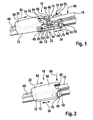
- FIG. 1 1 shows a wiper blade adapter device 10 with a wiper blade 48 and a wiper arm 18 shown in partial detail.
- the wiper blade adapter device 10 has a wiper blade adapter 12 which has a receiving region 14 which is provided to receive at least one wiper arm adapter 16 of the wiper arm 18.
- the wiper blade adapter 12 is captively connected to the wiper blade 48 ( FIG. 5 ).
- the wiper blade adapter 12 has on its underside a contact region which, with its contour, corresponds to a contour of a contact region of the wiper blade upper side.
- the wiper blade adapter 12 has a longitudinal extension 24 which corresponds in part to a longitudinal extent of the wiper blade 48.
- the receiving region 14 is arranged in the wiper blade adapter 12 and partially surrounded by six extensions 50, 52, 54, 56, 58, 60 of the wiper blade adapter 12.
- the six extensions 50, 52, 54, 56, 58, 60 extend orthogonally to a base 62 of the wiper blade adapter 12 (FIG. FIGS. 1 . 4 and 5 ). Further, the extensions 50, 52, 54, 56, 58, 60 in two rows of three of the extensions 50, 52, 54, 56, 58, 60 along the longitudinal extension 24 of the wiper blade adapter 12 at two parallel outer edges 104, 106 of the Base 62 of the wiper blade adapter 12 is arranged ( FIG. 4 ).
- the receiving region 14 has a receiving element 64, which is provided to secure the inserted Wischarmadapter 16 in two directions.
- the receiving element 64 is formed by a rectangular extension. Furthermore, the receiving element 64 is orthogonal to the base 62 of the wiper blade adapter 12 from.
- the receiving element 64 is arranged between two of the six extensions 54, 56, so that the longitudinal extent 24 orthogonal planes exist, which extend through the receiving element 64 and the extensions 54, 56.
- the receiving element 64 and the six extensions 50, 52, 54, 56, 58, 60 of the wiper blade adapter 12 extend to a common plane, which represents an overall height of the wiper blade adapter 12 ( FIG. 4 ).
- the wiper arm adapter 16 is captive and integrally formed with the wiper arm 18 and has a rectangular recess 66.
- the recess 66 has a cross-sectional shape approximately a cross-sectional shape of the receiving element 64 corresponds.
- the wiper arm adapter 16 is pushed with the rectangular recess 66 orthogonal to the base surface 62 on the receiving element 64, so that the wiper arm 18 has a Hauptausdehnungsraum, which corresponds approximately to a main extension direction of the wiper blade 48.
- the wiper arm adapter 16 and the wiper arm 18 are secured by being pushed against movement in a plane of movement parallel to a plane of the base 62.
- the wiper arm 18 is captively connected to a wiper arm 16 remote from the end of a wiper motor not visible.
- the wiper blade adapter device 10 has a wiper blade adapter cover 20, which is provided to hold the wiper arm adapter 16 of the wiper arm 18 in the receiving region 14, and a guide unit 22, via which the wiper blade adapter cover 20 is guided on the wiper blade adapter 12 along a path.
- a wiper blade adapter cover 20 of the wiper arm 16 of the wiper blade adapter 12 is detachable.
- the wiper arm adapter 16 can be removed from the receiving element 64 of the receiving region 14 of the wiper blade adapter 12 in a direction that is repelent from the base surface 62 of the wiper blade adapter 12, orthogonally to the base surface 62 of the wiper blade adapter 12.
- FIG. 1 illustrated position of the wiper blade adapter cover 20 of the wiper arm 16 of the wiper blade adapter 12 is detachable.
- the wiper arm adapter 16 can be removed from the receiving element 64 of the receiving region 14 of the wiper blade adapter 12 in a direction that is repelent from the base surface 62 of the
- the wiper blade adapter cover 20 serves to insert the wiper arm adapter 16 in the receiving area 14.
- the wiper blade adapter cover 20 has a rectangular basic shape with two open sides, wherein a base side with a largest extension and a front side are opened with a smallest dimension ( FIG. 3 ).
- the guide unit 22 of the wiper blade adapter device 10 is provided to guide the wiper blade adapter cover 20 translationally in the longitudinal extent 24 of the wiper blade adapter 12 on the wiper blade adapter 12.
- the guide unit 22 has for this purpose on the wiper blade adapter 12 four guide recesses 26, 28, 30, 32, which are formed by four guide grooves.
- the guide unit 22 has on the wiper blade adapter cover 20 two guide elements 34, 36, which are formed by two web-shaped guide rails.
- the guide recesses 26, 28, 30, 32 are arranged on four of the extensions 50, 52, 54, 56 of the wiper blade adapter 12, which are each arranged directly next to one another in the two rows ( FIG. 4 ).
- the guide recesses 26, 28, 30, 32 extend parallel to the longitudinal extension 24 of the wiper blade adapter 12, wherein in each case two of the guide recesses 26, 30; 28, 32 are arranged in an extension to each other.
- the guide recesses 26, 28, 30, 32 are arranged on the receiving region 14 opposite sides of four of the extensions 50, 52, 54, 56 of the wiper blade adapter 12.
- the guide elements 34, 36 (in FIG.
- the guide elements 34, 36 are web-shaped and each have a rounded contour in the direction of the receiving region 14 (FIG. FIG. 3 ).
- the guide elements 34, 36 are arranged on two opposite inner sides 92 of side walls 72, 74 of the wiper blade adapter cover 20 parallel to a longitudinal extent of the wiper blade adapter cover 20 ( FIG. 3 ).
- the guide elements 34, 36 extend over an entire longitudinal extent of the inner sides 92.
- the guide elements 34, 36 are intended to engage in the guide recesses 26, 28, 30, 32 of the wiper blade adapter 12 (FIG. FIG. 3 ).
- the wiper blade adapter cover 20 is detachable from the wiper blade adapter 12. If the wiper blade adapter cover 20 is pushed against the two guide recesses 30, 32, with which the guide elements 34, 36 are still disengaged, the guide elements 34, 36 are disengaged from the first guide recesses 26, 28. Thus, the wiper blade adapter cover 20 is away from the wiper blade adapter 12 is released and is removable from this, so that a connection between the wiper blade adapter cover 20 and the wiper blade adapter 12 is completely eliminated.
- the wiper blade adapter 12 and the wiper blade adapter cover 20 each have two latching means 38, 40, 42, 44, which are provided in a locked state to prevent a relative movement between the wiper blade adapter 12 and the wiper blade adapter cover 20.
- the two latching means 38, 40 of the wiper blade adapter cover 20 are formed by two latching elements 68, 70.
- the latching elements 68, 70 extend in each case in an extension to the opposite side walls 72, 74 of the wiper blade adapter cover 20.
- the two latching elements 68, 70 of the wiper blade adapter cover 20 are arranged on the opposite inner sides 92 of the side walls 72, 74 of the wiper blade adapter cover 20 ( FIG. 3 ).
- the latching elements 68, 70 are arranged on one of the open end side of the wiper blade adapter cover 20 facing the end of the inner sides 92. Furthermore, the latching elements 68, 70 are arranged between the guide elements 34, 36 and the opened base side ( FIG. 3 ). The latching elements 68, 70 are aligned parallel to the guide elements 34, 36. The locking elements 68, 70 protrude partially over the rectangular basic shape the wiper blade adapter cover 20 on the open front side ( FIG. 3 ). The projecting beyond the basic shape ends of the locking elements 68, 70 form resilient partial areas and each has a latching nose 94, 96 on ( FIG. 3 ).
- the two latching means 42, 44 of the wiper blade adapter 12 are in each case formed by a latching element 76, 78 which delimits a latching recess ( FIG. 4 ).
- the two latching elements 76, 78 are arranged on two of the extensions 58, 60 of the wiper blade adapter 12.
- the latching elements 76, 78 have main extensions which are aligned orthogonal to the base 62 of the wiper blade adapter 12 and parallel to the main extensions of the extensions 58, 60.
- the latching recesses have main extensions which extend parallel to the main extensions of the latching elements 76, 78.
- the locking elements 76, 78 each have on the side facing away from the respective locking elements 76, 78 recessed recesses sides a not further visible locking lug.
- the latching noses extend along an entire main extension of the latching elements 76, 78. Furthermore, the latching lugs on the extensions 58, 60 facing away from the latching elements 76, 78 are arranged.
- the first latching element 76 and the latching recess bounded therefrom, viewed from a direction of the longitudinal extension 24 of the wiper blade adapter 12, are arranged with its base side 80 next to the base surface 62 of the wiper blade adapter 12.
- the second detent element 78 and the detent recess bounded therefrom are arranged with their base side 82 on the base surface 62 of the wiper blade adapter 12 (FIG. FIGS. 1 . 4 , and 5 ).
- the wiper blade adapter cover 20 has on its inside 88 on one of the open base side opposite top wall 98 two pressing elements 100, 102 on ( FIG. 3 ).
- the pressing elements 100, 102 are formed by two roof-shaped inwardly projecting extensions, which are intended to press the wiper arm adapter 16 of the wiper arm 18 in an assembled state on the receiving element 64 of the receiving region 14 of the wiper blade adapter 12.
- the wiper arm adapter 16 of the wiper arm 18, as already described, is pushed perpendicular to the base surface 62 of the wiper blade adapter 12 onto the receiving element 64 of the receiving region 14 of the wiper blade adapter 12 before the wiper blade adapter cover 20 has been pushed completely onto the wiper blade adapter 12 ( FIG. 1 ).
- the wiper blade adapter cover 20 is moved over the guide unit 22 along the longitudinal extension 24 of the wiper blade adapter 12, in a direction from the wiper blade adapter 12 toward the wiper arm 18, completely pushed onto the wiper blade adapter 12.
- the locking elements 68, 70 of the wiper blade adapter cover 20 are pushed into the recesses of the wiper blade adapter 12.
- the locking elements 68, 70 are resiliently deflected by the latching recesses limiting latching elements 76, 78 until the locking lugs 94, 96 of the locking elements 68, 70 of the wiper blade adapter cover 20 behind the non-visible locking lugs of the locking elements 76, 78 ( FIG. 2 ).
- the wiper blade adapter cover 20 is thus secured by a spring force of the locking elements 68, 70 against slipping back.
- the direction from the wiper blade adapter 12 to the wiper arm 18 in the longitudinal extension 24 of the wiper blade adapter 12 defines a mounting direction 84 of the wiper blade adapter cover 20.
- a direction perpendicular to the base 62 of the wiper blade adapter 12 defines a mounting direction 86 of the wiper arm adapter 16 and the wiper arm 18.
- the mounting direction 84 of the wiper blade adapter cover 20 is orthogonal to the mounting direction 86 of the wiper arm adapter 16 and the wiper arm 18.
- the wiper blade adapter cover 20 covers the wiper blade adapter 12 in the assembled state. In the mounted state, the inside 88 of the wiper blade adapter cover 20 bears against an end face 90 of the receiver element 64. The wiper arm adapter 16 is thereby blocked against movement opposite its mounting direction 86, which is orthogonal to the longitudinal extent 24.
- the pressing elements 100, 102 further push the wiper arm adapter 16 next to the receiving element 64 downward, in order to produce jamming of the wiper arm adapter 16 on the receiving element 64.
- the wiper arm adapter 16 is thus held positively and non-positively in the wiper blade adapter 12.
- a force exiting from the wiper arm adapter 16 and acting on the wiper blade adapter cover 20 counteracts the mounting direction 86 of the wiper arm adapter 16 that is orthogonal to the longitudinal extent 24.
- the wiper blade adapter cover 20 is secured in this direction by the guide unit 22.
- a force required for releasing the latching elements 68, 70 acts counter to the assembly direction 84 of the wiper blade adapter cover 20 extending parallel to the longitudinal extent 24.
- the force required for releasing the wiper blade adapter cover 20 is orthogonal to the force acting on the wiper blade adapter cover 20 by the wiper arm adapter 16.
- undesired loosening of the wiper blade adapter cover 20 from the wiper blade adapter 12 can advantageously be avoided.
Landscapes
- Engineering & Computer Science (AREA)
- Mechanical Engineering (AREA)
- Ink Jet (AREA)
- Paper (AREA)
Applications Claiming Priority (1)
| Application Number | Priority Date | Filing Date | Title |
|---|---|---|---|
| DE102011079131.0A DE102011079131A1 (de) | 2011-07-14 | 2011-07-14 | Wischblattadaptervorrichtung |
Publications (2)
| Publication Number | Publication Date |
|---|---|
| EP2546115A2 true EP2546115A2 (fr) | 2013-01-16 |
| EP2546115A3 EP2546115A3 (fr) | 2018-02-21 |
Family
ID=46466285
Family Applications (1)
| Application Number | Title | Priority Date | Filing Date |
|---|---|---|---|
| EP12175449.3A Withdrawn EP2546115A3 (fr) | 2011-07-14 | 2012-07-06 | Dispositif d'adaptation de raclette d'essuie-glace |
Country Status (2)
| Country | Link |
|---|---|
| EP (1) | EP2546115A3 (fr) |
| DE (1) | DE102011079131A1 (fr) |
Cited By (6)
| Publication number | Priority date | Publication date | Assignee | Title |
|---|---|---|---|---|
| USD895523S1 (en) | 2019-04-16 | 2020-09-08 | Trico Products Corporation | Coupler for windshield wiper |
| USD896156S1 (en) | 2019-04-16 | 2020-09-15 | Trico Products Corporation | Coupler for windshield wiper |
| USD904275S1 (en) | 2019-04-16 | 2020-12-08 | Trico Products Corporation | Adapter for windshield wiper arm |
| CN114096444A (zh) * | 2019-07-19 | 2022-02-25 | 罗伯特·博世有限公司 | 具有滑块的片连接装置 |
| US11529931B2 (en) | 2018-02-19 | 2022-12-20 | Trico Products Corporation | Windshield wiper arm adapter, coupler and assembly |
| CN116940486A (zh) * | 2021-09-02 | 2023-10-24 | 宝马股份公司 | 用于机动车的雨刷系统的装置 |
Family Cites Families (6)
| Publication number | Priority date | Publication date | Assignee | Title |
|---|---|---|---|---|
| TWM288871U (en) * | 2005-09-23 | 2006-03-21 | Shih-Hsien Huang | Special connector for car wiper arm |
| KR100812773B1 (ko) * | 2007-05-04 | 2008-03-12 | 주식회사 캐프 | 차량용 와이퍼 장치 |
| DE102007021333A1 (de) * | 2007-05-07 | 2008-11-13 | Robert Bosch Gmbh | Anschlussvorrichtung zum gelenkigen Verbinden eines Wischblatts mit einem Wischarm |
| KR100891195B1 (ko) * | 2008-04-30 | 2009-04-02 | 주식회사 캐프 | 차량용 범용 와이퍼 장치 |
| US20100205763A1 (en) * | 2009-02-18 | 2010-08-19 | Chin Pech Co., Ltd. | Universal Adaptors for Connecting Wiper Blades to Wiper Arms |
| KR101381152B1 (ko) * | 2009-11-17 | 2014-04-04 | 로베르트 보쉬 게엠베하 | 와이퍼 암의 말단에서 연결 부재를 특히 평면 빔 구조의 와이퍼 블레이드에 연결하기 위한 어댑터 |
-
2011
- 2011-07-14 DE DE102011079131.0A patent/DE102011079131A1/de not_active Withdrawn
-
2012
- 2012-07-06 EP EP12175449.3A patent/EP2546115A3/fr not_active Withdrawn
Non-Patent Citations (1)
| Title |
|---|
| None |
Cited By (6)
| Publication number | Priority date | Publication date | Assignee | Title |
|---|---|---|---|---|
| US11529931B2 (en) | 2018-02-19 | 2022-12-20 | Trico Products Corporation | Windshield wiper arm adapter, coupler and assembly |
| USD895523S1 (en) | 2019-04-16 | 2020-09-08 | Trico Products Corporation | Coupler for windshield wiper |
| USD896156S1 (en) | 2019-04-16 | 2020-09-15 | Trico Products Corporation | Coupler for windshield wiper |
| USD904275S1 (en) | 2019-04-16 | 2020-12-08 | Trico Products Corporation | Adapter for windshield wiper arm |
| CN114096444A (zh) * | 2019-07-19 | 2022-02-25 | 罗伯特·博世有限公司 | 具有滑块的片连接装置 |
| CN116940486A (zh) * | 2021-09-02 | 2023-10-24 | 宝马股份公司 | 用于机动车的雨刷系统的装置 |
Also Published As
| Publication number | Publication date |
|---|---|
| DE102011079131A1 (de) | 2015-08-13 |
| EP2546115A3 (fr) | 2018-02-21 |
Similar Documents
| Publication | Publication Date | Title |
|---|---|---|
| EP2697104B1 (fr) | Dispositif adaptateur de balai d'essuie-glace | |
| EP2658755B1 (fr) | Adaptateur de raclette d'essuie-glace, notamment pour un dispositif essuie-glace de véhicule automobile | |
| EP3233591B1 (fr) | Dispositif d'adaptation | |
| DE102006046908A1 (de) | Wischblattrastvorrichtung | |
| EP3339114B1 (fr) | Dispositif d'essuie-glace et procédé de montage d'un dispositif d'essuie-glace | |
| DE102008001956A1 (de) | Wischblatt | |
| DE102011007247A1 (de) | Wischblattadaptervorrichtung | |
| DE102011079131A1 (de) | Wischblattadaptervorrichtung | |
| WO2017080783A1 (fr) | Dispositif essuie-glace | |
| WO2014075834A1 (fr) | Adaptateur top-lock pour balais d'essuie-glace | |
| EP2651717A1 (fr) | Dispositif d'essuie-glace | |
| WO2016162087A1 (fr) | Pompe submersible à préfiltre | |
| EP2651709B1 (fr) | Dispositif de balai essuie glace | |
| EP2651713B1 (fr) | Procédé de montage d'un dispositif balai d'essuie-glace | |
| EP2861470B1 (fr) | Système adaptateur de balai d'essuie-glace | |
| EP2651712B1 (fr) | Système de balai d'essuie-glace | |
| DE202011000739U1 (de) | Steckverbindungsanordnung für elektrische Leiter | |
| DE202010004995U1 (de) | Befestiger zur Befestigung eines ersten Bauteils an einem zweiten Bauteil | |
| WO2015127926A1 (fr) | Connecteur | |
| DE102015226764A1 (de) | Wischblattvorrichtung | |
| DE102012205835A1 (de) | Wischblattvorrichtung | |
| EP3317950B1 (fr) | Système pour positionnement de prise | |
| EP2651716B1 (fr) | Balai d'essuie glace | |
| DE102016115548B4 (de) | Indexierter Drehschalter | |
| DE102015218676A1 (de) | Wischblattvorrichtung und Verfahren zur Montage und/oder Demontage einer Wischblattvorrichtung |
Legal Events
| Date | Code | Title | Description |
|---|---|---|---|
| PUAI | Public reference made under article 153(3) epc to a published international application that has entered the european phase |
Free format text: ORIGINAL CODE: 0009012 |
|
| AK | Designated contracting states |
Kind code of ref document: A2 Designated state(s): AL AT BE BG CH CY CZ DE DK EE ES FI FR GB GR HR HU IE IS IT LI LT LU LV MC MK MT NL NO PL PT RO RS SE SI SK SM TR |
|
| AX | Request for extension of the european patent |
Extension state: BA ME |
|
| PUAL | Search report despatched |
Free format text: ORIGINAL CODE: 0009013 |
|
| AK | Designated contracting states |
Kind code of ref document: A3 Designated state(s): AL AT BE BG CH CY CZ DE DK EE ES FI FR GB GR HR HU IE IS IT LI LT LU LV MC MK MT NL NO PL PT RO RS SE SI SK SM TR |
|
| AX | Request for extension of the european patent |
Extension state: BA ME |
|
| RIC1 | Information provided on ipc code assigned before grant |
Ipc: B60S 1/38 20060101AFI20180115BHEP Ipc: B60S 1/40 20060101ALI20180115BHEP |
|
| 17P | Request for examination filed |
Effective date: 20180821 |
|
| RBV | Designated contracting states (corrected) |
Designated state(s): AL AT BE BG CH CY CZ DE DK EE ES FI FR GB GR HR HU IE IS IT LI LT LU LV MC MK MT NL NO PL PT RO RS SE SI SK SM TR |
|
| STAA | Information on the status of an ep patent application or granted ep patent |
Free format text: STATUS: THE APPLICATION IS DEEMED TO BE WITHDRAWN |
|
| 18D | Application deemed to be withdrawn |
Effective date: 20180822 |