EP2546155A1 - Sterilisationsreinigungsvorrichtung und sterilisationsreinigungsverfahren für kappen - Google Patents
Sterilisationsreinigungsvorrichtung und sterilisationsreinigungsverfahren für kappen Download PDFInfo
- Publication number
- EP2546155A1 EP2546155A1 EP11753175A EP11753175A EP2546155A1 EP 2546155 A1 EP2546155 A1 EP 2546155A1 EP 11753175 A EP11753175 A EP 11753175A EP 11753175 A EP11753175 A EP 11753175A EP 2546155 A1 EP2546155 A1 EP 2546155A1
- Authority
- EP
- European Patent Office
- Prior art keywords
- caps
- sterilization
- cap
- cleaning
- propulsion nozzle
- Prior art date
- Legal status (The legal status is an assumption and is not a legal conclusion. Google has not performed a legal analysis and makes no representation as to the accuracy of the status listed.)
- Withdrawn
Links
Images





Classifications
-
- B—PERFORMING OPERATIONS; TRANSPORTING
- B65—CONVEYING; PACKING; STORING; HANDLING THIN OR FILAMENTARY MATERIAL
- B65B—MACHINES, APPARATUS OR DEVICES FOR, OR METHODS OF, PACKAGING ARTICLES OR MATERIALS; UNPACKING
- B65B55/00—Preserving, protecting or purifying packages or package contents in association with packaging
- B65B55/02—Sterilising, e.g. of complete packages
- B65B55/04—Sterilising wrappers or receptacles prior to, or during, packaging
-
- A—HUMAN NECESSITIES
- A61—MEDICAL OR VETERINARY SCIENCE; HYGIENE
- A61L—METHODS OR APPARATUS FOR STERILISING MATERIALS OR OBJECTS IN GENERAL; DISINFECTION, STERILISATION OR DEODORISATION OF AIR; CHEMICAL ASPECTS OF BANDAGES, DRESSINGS, ABSORBENT PADS OR SURGICAL ARTICLES; MATERIALS FOR BANDAGES, DRESSINGS, ABSORBENT PADS OR SURGICAL ARTICLES
- A61L2/00—Disinfection or sterilisation of materials or objects, in general; Accessories therefor
- A61L2/16—Disinfection or sterilisation of materials or objects, in general; Accessories therefor using chemical substances
- A61L2/22—Phase substances, e.g. smokes or aerosols
-
- A—HUMAN NECESSITIES
- A61—MEDICAL OR VETERINARY SCIENCE; HYGIENE
- A61L—METHODS OR APPARATUS FOR STERILISING MATERIALS OR OBJECTS IN GENERAL; DISINFECTION, STERILISATION OR DEODORISATION OF AIR; CHEMICAL ASPECTS OF BANDAGES, DRESSINGS, ABSORBENT PADS OR SURGICAL ARTICLES; MATERIALS FOR BANDAGES, DRESSINGS, ABSORBENT PADS OR SURGICAL ARTICLES
- A61L2/00—Disinfection or sterilisation of materials or objects, in general; Accessories therefor
- A61L2/16—Disinfection or sterilisation of materials or objects, in general; Accessories therefor using chemical substances
- A61L2/18—Liquid substances
-
- A—HUMAN NECESSITIES
- A61—MEDICAL OR VETERINARY SCIENCE; HYGIENE
- A61L—METHODS OR APPARATUS FOR STERILISING MATERIALS OR OBJECTS IN GENERAL; DISINFECTION, STERILISATION OR DEODORISATION OF AIR; CHEMICAL ASPECTS OF BANDAGES, DRESSINGS, ABSORBENT PADS OR SURGICAL ARTICLES; MATERIALS FOR BANDAGES, DRESSINGS, ABSORBENT PADS OR SURGICAL ARTICLES
- A61L2/00—Disinfection or sterilisation of materials or objects, in general; Accessories therefor
- A61L2/24—Apparatus using programmed or automatic operation
-
- B—PERFORMING OPERATIONS; TRANSPORTING
- B65—CONVEYING; PACKING; STORING; HANDLING THIN OR FILAMENTARY MATERIAL
- B65B—MACHINES, APPARATUS OR DEVICES FOR, OR METHODS OF, PACKAGING ARTICLES OR MATERIALS; UNPACKING
- B65B55/00—Preserving, protecting or purifying packages or package contents in association with packaging
- B65B55/02—Sterilising, e.g. of complete packages
- B65B55/04—Sterilising wrappers or receptacles prior to, or during, packaging
- B65B55/10—Sterilising wrappers or receptacles prior to, or during, packaging by liquids or gases
-
- B—PERFORMING OPERATIONS; TRANSPORTING
- B67—OPENING, CLOSING OR CLEANING BOTTLES, JARS OR SIMILAR CONTAINERS; LIQUID HANDLING
- B67B—APPLYING CLOSURE MEMBERS TO BOTTLES JARS, OR SIMILAR CONTAINERS; OPENING CLOSED CONTAINERS
- B67B3/00—Closing bottles, jars or similar containers by applying caps
- B67B3/003—Pretreatment of caps, e.g. cleaning, steaming, heating or sterilizing
-
- A—HUMAN NECESSITIES
- A61—MEDICAL OR VETERINARY SCIENCE; HYGIENE
- A61L—METHODS OR APPARATUS FOR STERILISING MATERIALS OR OBJECTS IN GENERAL; DISINFECTION, STERILISATION OR DEODORISATION OF AIR; CHEMICAL ASPECTS OF BANDAGES, DRESSINGS, ABSORBENT PADS OR SURGICAL ARTICLES; MATERIALS FOR BANDAGES, DRESSINGS, ABSORBENT PADS OR SURGICAL ARTICLES
- A61L2103/00—Materials or objects being the target of disinfection or sterilisation
- A61L2103/23—Containers other than laboratory or medical, e.g. bottles or mail
-
- A—HUMAN NECESSITIES
- A61—MEDICAL OR VETERINARY SCIENCE; HYGIENE
- A61L—METHODS OR APPARATUS FOR STERILISING MATERIALS OR OBJECTS IN GENERAL; DISINFECTION, STERILISATION OR DEODORISATION OF AIR; CHEMICAL ASPECTS OF BANDAGES, DRESSINGS, ABSORBENT PADS OR SURGICAL ARTICLES; MATERIALS FOR BANDAGES, DRESSINGS, ABSORBENT PADS OR SURGICAL ARTICLES
- A61L2202/00—Aspects relating to methods or apparatus for disinfecting or sterilising materials or objects
- A61L2202/10—Apparatus features
- A61L2202/15—Biocide distribution means, e.g. nozzles, pumps, manifolds, fans, baffles, sprayers
Definitions
- the present invention relates to a cap sterilization-cleaning device, and in particular relates to a chute-type cap sterilization-cleaning device which obtains propulsive force for transferring caps simultaneously with sterilizing and cleaning the caps by continuous injection of a sterilization-cleaning liquid from a plurality of nozzles disposed along a chute, wherein even when the transfer of the caps is stopped during the operation of a propulsion nozzle, deformation of the caps in the chute can be favorably prevented.
- a sterile filling system such as an aseptic filling system
- a synthetic resin cap upon mounting a synthetic resin cap on a bottle (container) in which content such as a soft drink is filled, the cap is subject to sterilization and cleaning prior to supplying the cap to a capper.
- cap sterilization-cleaning methods in the case, generally known are a method and a device for sterilizing and cleaning caps while transferring the caps in a chute based on their own weight (for instance, refer to Patent Document 1), and a method and a device for sterilizing and cleaning caps while transferring the caps in a turret or a drum-shaped star wheel (for instance, refer to Patent Documents 2 and 3).
- a cap transfer chute creates a transfer space with a plurality of rod-shaped guides disposed at least on the left, right, top and bottom in order to support the caps sideways to enable the cap to rotate, and the caps are transferred by passing through such transfer space.
- the caps transferred through the chute are sterilized and cleaned by injection of a sanitizer or aseptic water to the inner and outer surfaces of the caps from nozzles which are disposed at appropriate intervals on the left, right, top and bottom along the transfer passage.
- the sterilization-cleaning liquid is injected from the nozzles at an angle relative to the transfer direction so that the injected flow of the sterilization-cleaning liquid injected from the nozzles disposed along the chute is not obstruct the transfer of the caps.
- the chute-type cap sterilization-cleaning device which obtains propulsive force for transferring caps simultaneously with sterilizing and cleaning the caps with the sterilization-cleaning liquid injected from the nozzles, there are advantages in that the system can be configured inexpensively comparison to a device which sterilizes and cleans the caps while transferring the caps by using power of a turret or the like since mechanical power is not required, and the space can be used efficiently since the transfer passage of the caps can be configured in the longitudinal direction (vertical direction). Nevertheless, since a sanitizer is normally heated, during the sterilization process, the caps are transferred while being subjected to accumulated pressure in the chute and while being heated. A dividing device for controlling the transit time and processing speed is provided at the downstream of the chute.
- an object of this invention is to provide a chute-type cap sterilization-cleaning device which obtains propulsive force for transferring caps simultaneously with sterilizing and cleaning the caps by continuous injection of a sterilization-cleaning liquid from a plurality of nozzles disposed along a chute, wherein, even when the transfer of the caps is stopped during the operation of the propulsion nozzle, deformation of the caps in the chute can be favorably prevented.
- the cap sterilization-cleaning device of the present invention includes a chute and a dividing device in a cap transfer passage, a propulsion nozzle for injecting a sterilization-cleaning liquid to a plurality of caps in a transfer direction of the caps, a reverse propulsion nozzle for injecting the sterilization-cleaning liquid to the plurality of caps in a direction opposite to the transfer direction of the caps, a control unit for issuing a command to start injection by the reverse propulsion nozzle when the dividing device is stopped, and a control valve for issuing the command.
- the cap sterilization-cleaning method of the present invention when a plurality of caps to be sprayed with a sterilization-cleaning liquid which is injected in a cap transfer passage configured from a chute and a dividing device along a transfer direction of caps from propulsion nozzles are sprayed with the sterilization-cleaning liquid while the caps are stemmed due to stoppage of the dividing device, the sterilization-cleaning liquid is sprayed from a reverse propulsion nozzle to the caps in a direction opposite to a direction of transferring the caps.
- the cap sterilization-cleaning device and the sterilization-cleaning method of this invention can favorably inhibit the deformation of the caps by negating or weakening the accumulated pressure by spraying the sterilization-cleaning liquid to the caps also from the reverse propulsion nozzle.
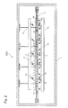
- Fig. 1 is an explanatory drawing of the main part showing a cap sterilization-cleaning device 100 of the present invention.
- Fig. 2 is a plan view of the main part which shows Fig. 1 from above.
- the cap sterilization-cleaning device 100 performs the sterilization-cleaning of the caps C by using propulsion nozzles 2a, 2b, 2c, 2d of different injection modes (injected flow center, intended target, intersection angle ⁇ , divergence angle ⁇ and the like described later), and additionally using a reverse propulsion nozzle 2e as needed.
- the cap sterilization-cleaning device 100 can evenly sterilize and clean the caps C with a sterilization-cleaning liquid which is injected from the plurality of propulsion nozzles provided to the outer periphery of a pipe disposed along a chute transfer passage 1, and, without requiring a power mechanism such as a turret, stably transfer the caps C in the chute transfer passage 1 in a predetermined direction by using the force of the injected flow of the sterilization-cleaning liquid as the propulsive force.
- the cap sterilization-cleaning device 100 additionally comprises a reverse propulsion nozzle which generates reverse propulsion force for negating or weakening the influence of the propulsive force, even if the dividing device is stopped while the sterilization-cleaning liquid is still being injected from the propulsion nozzles to the caps C and the plurality of caps C are consequently stemmed and backed up between the dividing devices, it is possible to relax the so-called crammed state where the plurality of caps are squeezed together and favorably inhibit the deformation of caps while continuing the sterilization-cleaning of caps by injecting the sterilization-cleaning liquid from the reverse propulsion nozzle to the caps C.
- the cap sterilization-cleaning device 100 is configured by mainly comprising a chute transfer passage 1 as the transfer passage of the caps C, an upper propulsion nozzle 2a, a lower propulsion nozzle 2b, a right propulsion nozzle 2c (refer to Fig.
- a left propulsion nozzle 2d for applying propulsive force for causing the caps C to advance in a predetermined direction along the chute transfer passage 1 based on the force of the injected flow of the sterilization-cleaning liquid simultaneously with injecting the sterilization-cleaning liquid to the caps C and sterilizing and cleaning an inner surface or an outer surface of the caps C, an upper propulsion supply pipe 3a, a lower propulsion supply pipe 3b, a right propulsion supply pipe 3c (refer to Fig. 2 ) and a left propulsion supply pipe 3d as pipes for supplying the sterilization-cleaning liquid to the "propulsion nozzles", a reverse propulsion nozzle 2e (refer to Fig.
- a reverse propulsion supply pipe 3e (refer to Fig.
- an entrance side dividing device 4 for supplying the caps C at a predetermined time interval to a sterilization-cleaning zone where the caps C are sterilized and cleaned (range where the sterilization-cleaning liquid is sprayed in the chute transfer passage 1; hereinafter also referred to as the "sterilization-cleaning chute portion")
- an exit side dividing device 5 for extracting the caps at the same time interval from the sterilization-cleaning chute portion in synch with the entrance side dividing device 4 and sending the caps C downstream
- a chute transfer passage support member 6 for supporting the chute transfer passage 1
- a chamber 7 for preventing the penetration of bacteria, dust and dirt and preventing the scattering of the sterilization-cleaning liquid
- pressure sensors 8a, 8b, 8c, 8d, 8e only 8a is shown in Fig.
- injection pressure the pressure of each of the supply pipes 3a, 3b, 3c, 3d, 3e
- flow sensors 9a, 9b, 9c, 9d, 9e (only 9a is shown in Fig. 1 ) for measuring the flow rate of the sterilization-cleaning liquid which flows into each of the supply pipes 3a, 3b, 3c, 3d, 3e and temperature sensors (only the temperature sensor connected to the upper propulsion supply pipe 3a is shown in Fig.
- a flow regulating valve or a pressure regulating valve is preferably provided midway to the respective supply pipes 3a, 3b, 3c, 3d, 3e in addition to the solenoid valve so that the flow rate can be changed, but it is even more preferable to provide a proportional control valve to automatically control the flow rate of the respective supply pipes.
- the proportional control valve may be caused to function as the control valve in substitute for the solenoid valve.
- a medicinal solution such as warm water or aseptic water
- aseptic water hereinafter referred to as the "warm water”
- the operation of the controller 11 will be described later with reference to Figs. 9 and 10 . The respective configurations are now explained.
- the chute transfer passage 1 is configured, for example, from six rod-shaped guiderails, and is a transfer space passage through which the caps C are passed internally.
- the shape of the chute transfer passage 1 is, for example, formed in a so-called crank shape of a vertical portion for lowering the caps C in a vertical direction as shown in Fig. 1 ⁇ a horizontal portion for moving the caps C in a horizontal direction ⁇ and a vertical portion.
- a gap is secured between the respective guiderails, it is possible to apply propulsive force to the caps C by spraying the sterilization-cleaning liquid injected from the propulsion nozzles to the caps C, and sufficiently sterilize and clean the inner surface or outer surface of the caps C while transferring the caps C.
- the transfer turret of the dividing devices 4, 5 can be inserted through the gap between the guiderails and place and cut the caps C which are being transferred in the pocket of the turret, it is also possible to maintain the transfer time (processing time) of the caps C to the intended value while maintaining the number of caps C (processing quantity) to the intended value (30 caps in this embodiment) in the sterilization-cleaning chute portion (horizontal portion) based on the dividing devices 4, 5.
- the sterilization-cleaning chute portion (horizontal portion) is configured in the form of one stage
- the sterilization-cleaning chute portion (horizontal portion) may also be configured in a connected form in multiple stages via the dividing device or the vertical portion.
- a horizontal portion that follows a preceding horizontal portion may be connected to the lower part of the preceding horizontal portion
- the vertical portion and horizontal portion may also be inclined and provided as a slope as needed.
- a simple open/close-type partition or the like may be used.
- the dividing device may also be provided only to the horizontal portion or only to the vertical portion of the chute transfer passage.
- the transfer force (propulsive force) of the caps C is mainly gravity in the vertical portion of the chute transfer passage 1, but the force (head) of the injected flow of each sterilization-cleaning liquid injected from each of the propulsion nozzles 2a, 2b, 2c, 2d becomes the main propulsive force in the horizontal portion (sterilization-cleaning chute portion).
- the transfer posture of the caps C in the chute transfer passage 1 is preferably a sideways posture where the opening of the caps C is facing sideways as shown in the drawing since it is also possible to reduce the loss of propulsive force by rolling and transferring the caps C.
- the caps C are rightly aligned in a state of preferably coming into contact with the injected flow from the respective nozzles.
- the numbers indicated along the sterilization-cleaning chute portion of the chute transfer passage 1 are the numbers (Nos.) for explaining the (relative) position of the caps C in the sterilization-cleaning chute portion which are the target (intended target) of the injected flow center of the nozzles 2a, 2b, 2c, 2d, 2e.
- the injected flow center of the upper propulsion nozzle 2a is targeting the respective caps C of No. 1, No. 7, No. 13,..., No. 25.
- the intended number of caps C in the sterilization-cleaning chute portion was set to 30. Accordingly, numbers 1 to 30 are given to the caps C.
- the cap sterilization-cleaning device 100 sterilizes and cleans the inner surface and outer surface of the caps C by normally using four types of propulsion nozzles 2a, 2b, 2c, 2d.
- the respective propulsion nozzles are provided to the outer periphery of the supply pipe such that, with the respective injected flow centers not being overlappingly directed to a single cap, the sterilization-cleaning liquid from one propulsion nozzle is injected to a single cap C.
- the number of caps C secured in the sterilization-cleaning chute portion is 30, and, as the respective nozzles to spray the sterilization-cleaning liquid to the 30 caps C, a total of 30 propulsion nozzles; namely, five upper propulsion nozzles 2a, five lower propulsion nozzles 2b, fifteen right propulsion nozzles 2c, and five left propulsion nozzles 2d are used for sterilizing and cleaning the caps C.
- a total of 30 propulsion nozzles namely, five upper propulsion nozzles 2a, five lower propulsion nozzles 2b, fifteen right propulsion nozzles 2c, and five left propulsion nozzles 2d are used for sterilizing and cleaning the caps C.
- the number of propulsion nozzles is preferably increased as needed as shown in the drawing, but it is also possible to use or arbitrarily adjust (for instance, adjustment for intermittently increasing the rotating speed) the rotating speed of the entrance side dividing device, or incline the chute to slope downward toward the outer side.
- the respective propulsion nozzles and the reverse propulsion nozzle are provided to the outer periphery of the supply pipe provided parallel to the sterilization-cleaning chute portion, and disposed so that the injected flow center thereof forms a predetermined intersection angle ⁇ relative to the transfer direction of the caps C, or, in addition to the predetermined intersection angle ⁇ , so as to inject the sterilization-cleaning liquid at an injection mode of a predetermined divergence angle ⁇ relative to the injected flow center.
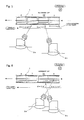
- intersection angle ⁇ refers to, as shown in Fig. 3 , an angle that is formed by the injected flow center and the cap transfer direction (advancing direction), and the term “divergence angle ⁇ " refers to the center angle when the injected flow is approximated as a fan shape.
- F fan-shaped injection in which the divergence angle ⁇ is not 0 degrees
- the respective supply pipes 3a, 3b, 3c, 3d, 3e are provided along the sterilization-cleaning chute portion, and simultaneously supply the sterilization-cleaning liquid (warm water in this embodiment) to the respective propulsion nozzles 2a, 2b, 2c, 2d and the reverse propulsion nozzle 2e disposed at the outer periphery thereof. Moreover, the warm water is pressure-fed from an upstream sterilization-cleaning liquid tank 10 via the pump.
- the respective injection pressures of the respective supply pipes 3a, 3b, 3c, 3d, 3e are retained at a suitable constant pressure (for example, 0.1 to 0.3 [MPa]) by a publicly known pressure control mechanism (for instance, a pressure regulating valve or a relief valve, and in this embodiment a pressure regulating valve not shown in the drawing and provided respectively between the inlets of the respective supply pipes from the respective solenoid valves) .
- a suitable constant pressure for example, 0.1 to 0.3 [MPa]
- a publicly known pressure control mechanism for instance, a pressure regulating valve or a relief valve, and in this embodiment a pressure regulating valve not shown in the drawing and provided respectively between the inlets of the respective supply pipes from the respective solenoid valves
- the respective supply pipes 3a, 3b, 3c, 3d, 3e are of a tube shape
- the shape thereof so as long as the respective nozzles 2a, 2b, 2c, 2d, 2e can be provided at the outer periphery thereof along the sterilization-cleaning chute portion, and the pressure control mechanism can also be provided.
- the propulsion nozzles and the reverse propulsion nozzle may also be piped and connected in a manner of being branched from the solenoid valve for turning ON/OFF the opening and closing of the respective nozzles.
- the dividing devices 4, 5 include a pocket at the outer periphery of the wheel as a transfer turret where the caps C enter, and in this embodiment the dividing devices 4 and 5, in mutual synchronization, send the caps C to the sterilization-cleaning chute portion at a predetermined time interval (processing time) and simultaneously send the same number of caps C that have been sterilized and cleaned from the sterilization-cleaning chute portion toward the downstream side. Accordingly, the number of caps C (processing quantity) that is secured in the sterilization-cleaning chute portion by the dividing devices 4, 5 is always kept constant. Moreover, the dividing devices 4, 5 keep the sterilization-cleaning time (processing time) constant by also keeping constant the processing quantity per unit time in the sterilization-cleaning chute portion of the caps C.
- the pressure sensors 8a, 8b, 8c, 8d, 8e and the flow sensors 9a, 9b, 9c, 9d, 9e are used for determining whether the propulsion nozzles 2a, 2b, 2c, 2d and the reverse propulsion nozzle 2e are operating or stopped by confirming whether at least one value of either the pressure or flow rate has reached a predetermined value (range) (details will be explained later with reference to Figs. 9 and 10 ).
- the sterilization-cleaning liquid tank 10 stores, for example, warm water pre-heated to 85°C, and, by opening (turning ON) the respective solenoid valves blocking the passage between the sterilization-cleaning liquid tank 10 and the respective supply pipes 3a, 3b, 3c, 3d, 3e, the warm water is pressure-fed to the respective supply pipes 3a, 3b, 3c, 3d, 3e by a pump, and the warm water can thereby be injected from the respective nozzles 2a, 2b, 2c, 2d, 2e to the caps C based on the respective injection modes.
- the warm water can also be prepared by heating aseptic water of ordinary temperature using a heating means such as a boiler.
- the controller 11 controls the collection of angle information (for instance, publicly known rotary encoder signals) and the operation of the respective turrets of the dividing devices 4, 5, and controls the injection of each of the propulsion nozzles 2a, 2b, 2c, 2d and the reverse propulsion nozzle 2e based on each piece of sensor information of the pressure sensors 8a, 8b, 8c, 8d, 8e and the flow sensors 9a, 9b, 9c, 9d, 9e. Moreover, the start/stop of the injection of the respective nozzles is performed, for instance, by opening (turning ON)/closing (turning OFF) the solenoid valve on the downstream side of the sterilization-cleaning liquid tank 10.
- angle information for instance, publicly known rotary encoder signals
- Fig. 4 is a cross section of line B-B of Fig. 1 , and is an explanatory drawing showing the relative positional relationship of the "propulsion nozzle” and "reverse propulsion nozzle” relative to the cap C.
- the upper propulsion nozzle 2a and the lower propulsion nozzle 2b sterilize and clean the outer periphery (outer surface) of the body of the caps C
- the left propulsion nozzle 2d sterilizes and cleans the outer surface of the top of the caps C
- the right propulsion nozzle 2c and the reverse propulsion nozzle 2e sterilize and clean the inner periphery (inner surface) of the caps C.
- the respective nozzles 2a, 2b, 2c, 2d belonging to the "propulsion nozzles” are disposed along the sterilization-cleaning chute portion so as to inject the warm water to mutually different caps C in a one-to-one mode without overlapping with each other.
- the caps C for instance, the respective caps C of No. 7, No. 13, No. 19, and No. 25 in Table 1 to receive (to be exposed to) the injected flow of the reverse propulsion nozzle 2e among the caps C simultaneously receive two injected flows of the "propulsion nozzles" and the "reverse propulsion nozzle” during the temporary stop processing explained later.
- Table 1 shows the injection in the respective caps of each of the propulsion nozzles and the reverse propulsion nozzle according to the present invention.
- the left propulsion nozzle 2d injects the respective caps C of No. 5, No. 11, No.
- the caps near the exit side dividing device 5 have a low degree of contribution to the relaxation of the accumulated pressure and have thereby been omitted.
- the intersection angle ⁇ and the divergence angle ⁇ are merely an example, and the setting range is normally intersection angle: 0 ⁇ ⁇ ⁇ 180° and divergence angle: 0 ⁇ ⁇ ⁇ 120° depending on the sterilization-cleaning conditions and other matters.
- the intersection angle of the propulsion nozzles is 0 ⁇ ⁇ ⁇ 90° (transfer direction side of the caps)
- the intersection angle of the propulsion nozzles is preferably 10° ⁇ ⁇ ⁇ 80°, and more preferably 30° ⁇ ⁇ ⁇ 50°.
- intersection angle of the reverse propulsion nozzle is 90° ⁇ ⁇ ⁇ 180° (side that is opposite to the transfer direction of the caps), the intersection angle of the reverse propulsion nozzle is preferably 105° ⁇ ⁇ ⁇ 150° because it is difficult to obtain sufficient reverse propulsive force when ⁇ ⁇ 105°, and the disposition of the reverse propulsion nozzle is difficult when ⁇ > 150°.
- 115° ⁇ ⁇ ⁇ 140° is more preferable.
- intersection angle ⁇ of the respective nozzles 2a to 2e connected to the pipes 3a to 3e may be changed arbitrarily without setting it to a fixed angle so as long as such intersection angle ⁇ falls within a range where the propulsion nozzles and the reverse propulsion nozzle can fulfill their predetermined roles (in this embodiment, 2a to 2d are 0° ⁇ ⁇ ⁇ 90° with the propulsion nozzles, and 2e is 90° ⁇ ⁇ ⁇ 180° with the reverse propulsion nozzle).
- the setting may also be such that the intersection angle ⁇ increases or decreases as the cap position moves downstream so that the intersection angle ⁇ is deformed linearly according to the cap position.
- the reverse propulsion nozzle 2e can yield greater reverse propulsion force by directing the injected flow to come into contact with the side wall of the inner surface of the cap on the upstream side when the caps are arranged as shown in Fig. 1 .
- a sterilization-cleaning liquid injection nozzle of ⁇ 90° which does not belong to either of the propulsion nozzles and the reverse propulsion nozzle.
- the upper propulsion nozzle 2a targets, in the fan shape mode (F), the outer surface of the cap body of cap Nos. 6n-5 (n is an integer of 1 to 5)
- the lower propulsion nozzle 2b targets, in the fan shape mode, the outer surface of the cap body of cap Nos. 6n-3 (n is an integer of 1 to 5)
- the right propulsion nozzle 2c injects, in the straight mode (S1), the inner surface of cap Nos. 6n-4 (n is an integer of 1 to 5)
- the left propulsion nozzle 2d targets, in the fan shape mode (F), the outer surface of the cap top of cap Nos. 6n-1 (n is an integer of 1 to 5), and the reverse propulsion nozzle 2e targets, in the straight mode (S2), the inner surface of cap Nos. 6n + 1 (n is an integer of 1 to 4) adjacent to the downstream side of the reference caps when cap Nos. 6n + 2 are used as the "reference cap”.
- Table 2 shows the maximum value of ovality of the respective caps C when the sterilization-cleaning liquid is injected to the caps C while a predetermined 30 caps C are retained and the dividing devices 4, 5 are stopped in the respective sterilization-cleaning chute portions of the conventional technology and the present invention.
- ovality refers to the amount showing the difference between the maximum value of the outer diameter of a cap skirt and the minimum value of the outer diameter of the cap skirt shown in cap No. 9 of Fig. 5 , and this ovality was used for defining the amount of deformation of the cap. Moreover, the smaller the ovality, the more relaxed the crammed state of the sterilization-cleaning chute portion.
- Table 2(a) shows the maximum value of ovality of the respective caps of the sterilization-cleaning chute portion in a case of not providing the reverse propulsion nozzle 2e as a comparative example; that is, in the sterilization-cleaning chute portion that only comprises the propulsion nozzle and does not include the reverse propulsion nozzle 2e in Table 1, and Table 2(b) shows the maximum value of ovality of the caps in the sterilization-cleaning chute portion comprising each of the propulsion nozzle and the reverse propulsion nozzle according to the present invention.
- the reverse propulsion nozzle 2e was disposed so that the warm water can be injected to the inner surface of the cap C which is one downstream relative to the cap C (reference cap No. 8 in Fig.
- the stop time (injection time) in the sterilization-cleaning chute portion was set to "stop time of 20 seconds", “stop time of 60 seconds", and "stop time of 180 seconds".
- the 30 caps C in the sterilization-cleaning chute portion continue to receive the propulsive force from the propulsion nozzles 2a, 2b, 2c, 2d and become a crammed state in a state where movement is restricted by the exit side dividing device 5 (while the caps C are affected by the drive force of the entrance side dividing device 4 if the entrance side dividing device 4 continues to operate, in order to simplify the explanation, the explanation continues as follows on the supposition that the entrance side dividing device 4 also stopped simultaneously with the stoppage of the exit side dividing device 5).
- the respective caps C are subject to the sum of propulsive forces of all caps C on the right side (upstream side) of itself from the cap C on the right side (adjacent on the upstream side), and, based on the principle of action and reaction, simultaneously be subject to the sum of propulsive forces from all caps C on the upstream side of itself, and, when that cap C is also receiving propulsive force by the injection of warm water from the propulsion nozzles, that cap C is also subject to force that is substantially equal to a value obtained by further adding such propulsive force from the cap C on the left side (adjacent on the downstream side) of itself.
- the respective caps C are placed in a state of continuously receiving the compressive load from the adjacent caps on the upstream side and the downstream side in a high-temperature state.
- the compressive load (hereinafter also referred to as the "accumulated pressure of the caps") increases from the upstream side toward the downstream side, and becomes maximum at the cap C of No. 1 if excluding the influence of the turret pocket of the exit side dividing device 4.
- the cap sterilization-cleaning device 100 when the dividing devices 4, 5 are stopped, the warm water is injected from the reverse propulsion nozzle 2e based on the injection mode, and the reverse propulsion force caused by the injected flow of the warm water is used to negate or weaken the influence of the propulsive force and relax the accumulated pressure of the caps. If the reverse propulsion nozzles 2e are scattered at a plurality of locations as described above, that is preferable since the accumulated pressure of the caps can be effectively relaxed by reducing the force of injection of each reverse propulsion nozzle 2e and reduce the reverse propulsive force to be applied to one cap.
- Fig. 6 is an explanatory drawing showing the injection of the reverse propulsion nozzle according to another embodiment of the present invention.
- Table 3 The relationship of the respective cap positions and the respective injection nozzles in this case is shown in Table 3.
- the respective injection modes of the propulsion nozzles 2a, 2b, 2c, 2d are the same as Table 1.
- the relationship of the caps C and the injection positions in the arrow view B-B of Fig. 1 is basically the same as the former embodiment and is as shown in Fig. 8 .
- the reverse propulsion supply pipe 3e and the reverse propulsion nozzle 2e were moved upward so that the injected flow of the reverse propulsion nozzle can more easily come into contact with the upper part of the outer surface of the body of the caps C.
- Table 4 shows the maximum value of ovality of the 30 retained caps in the injection modes of Table 3.
- the respective maximum values of the cap ovality at the stop times of 20 seconds, 60 seconds, and 180 seconds in the injection modes were 1.0 [mm], 1.2 [mm], and 1.4 [mm].
- Stop time 20 seconds 60 seconds 180 seconds Maximum value of ovality 1.0 mm 1.2 mm 1.4 mm
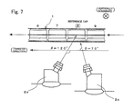
- Fig. 7 is an explanatory drawing showing the injection of the reverse propulsion nozzle according to yet another embodiment of the present invention.
- Table 5 The relationship of the respective cap positions and the respective injection nozzles in the case is shown in Table 5.
- the respective injection modes of the propulsion nozzles 2a, 2b, 2c, 2d are the same as Table 1. Moreover, the relationship of the caps C and the injection positions in the arrow view B-B of Fig. 1 is as shown in Fig. 8 .
- Table 6 shows the maximum value of ovality of the 30 caps in the injection modes of Table 5.
- the respective maximum values of the cap ovality at the stop times of 20 seconds, 60 seconds, and 180 seconds in the injection modes were 1.4 [mm], 1.4 [mm], and 1.4 [mm].
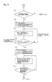
- Figs. 9 and 10 are flowcharts of the "temporary stop processing of the cap sterilization-cleaning device" which mainly show, as an example of the nozzle injection control of the present invention, the command control of the propulsion nozzles 2a, 2b, 2c, 2d and the reverse propulsion nozzle 2e of the controller 11 upon restarting the operation of the cap cleaning apparatus from the ordinary operating state thereof and after going through a temporary stop.
- the explanation starts with a state where the cap sterilization-cleaning device 100 which adopts the embodiment of Figs. 1 to 5 described above and Table 1 is normally being operated.
- the dividing devices 4, 5 are being operated, warm water is being injected from the respective propulsion nozzles 2a, 2b, 2c, 2d toward the inner surface or outer surface of the caps C, and the caps C are being transferred to a predetermined direction.
- the reverse propulsion nozzle 2e is in a stopped state.
- step S1 whether a temporary stop signal was received due to a command input operation or warning through use of a button by an operator is determined.
- the routine proceeds to step S2.
- the "temporary stop processing of the cap sterilization-cleaning device” is ended without performing any additional processing, and the routine returns to the main processing.
- step S2 the dividing devices 4, 5 are stopped and warm water is injected from the reverse propulsion nozzle 2e.
- the solenoid valve By issuing a command for turning ON (opening) the solenoid valve that is blocking the passage between the sterilization-cleaning liquid tank 10 and the reverse propulsion supply pipe 3e, the solenoid valve is opened and the warm water is supplied to the reverse propulsion supply pipe 3e, and the warm water is injected from the reverse propulsion nozzle 2e toward the inner surface of the caps C.
- the caps C are in a state of continuously receiving the warm water from the respective propulsion nozzles 2a, 2b, 2c, 2d or the reverse propulsion nozzle 2e, and the transfer thereof is stopped.
- a timer for monitoring whether the stoppage is for a long time is preferably reset and started at this time.
- step S3 the restart permission signal of the cap cleaning apparatus 100 is accepted, and a restart enable command based on the operator's button operation or the like and a signal input based on restart enabling according to an all-clear signal is accepted.
- step S4 whether a restart permission signal was received is determined.
- the routine proceeds to step S11.
- a restart permission signal was not received (No)
- this determination processing is repeated until a restart permission signal is received, but it is preferable to add processing for once stopping the propulsion nozzles and the reverse propulsion nozzle as shown in steps S5 to S11 of Fig. 10 in order to inhibit the wasteful consumption of energy and preventing abnormal deformation of caps when the stoppage extends over a long time.
- step S5 whether the predetermined time lapses the time that was set as a tolerable time from the perspective of inhibiting energy consumption and preventing abnormal deformation of caps is determined based on a value of the timer described above in step S2.
- the routine returns to the restart permission signal input acceptance processing of step S3 ( Fig. 9 ), and when the time has elapsed, the routine proceeds to step S6.
- step S6 the respective solenoid valves connected between the sterilization-cleaning liquid tank 10 and the respective supply pipes 3a, 3b, 3c, 3d, 3e are turned OFF (closed) as the processing for stopping the injection of warm water of the respective propulsion nozzles 2a, 2b, 2c, 2d and the reverse propulsion nozzle 2e.
- step S8 when a restart permission signal is not received, the routine immediately returns to step S7.
- step S9 to prepare for the operation of the recovered cap cleaning apparatus, warm water is injected from the respective propulsion nozzles 2a, 2b, 2c, 2d and the reverse propulsion nozzle 2e.
- the solenoid valves By turning ON (opening) the solenoid valves blocking the passage between the sterilization-cleaning liquid tank 10 and the respective supply pipes 3a, 3b, 3c, 3d, 3e, the warm water is supplied to the respective supply pipes 3a, 3b, 3c, 3d, 3e, and the warm water is simultaneously injected from the respective propulsion nozzles 2a, 2b, 2c, 2d and the reverse propulsion nozzle 2e toward the inner surface or outer surface of the caps C.
- the reason why the warm water to also be injected from the reverse propulsion nozzle 2e is to stop the transfer of the caps C in a state where the dividing devices 4, 5 are still stopped during the period that the injected flow of the respective nozzles becomes stable and the temperature of the warm water also reaches a predetermined temperature.
- the injection pressure in the respective supply pipes rises drastically, and the warm water temperature is of a low state since the pipes and the like are also cold and the injected flow from the respective nozzles is unstable.
- the caps C are sterilized and cleaned in an unstable state while being transferred and, consequently, there may be cases where the inner surface and outer surface of the caps C cannot be sterilized and cleaned evenly under desirable conditions. Accordingly, upon the startup of the propulsion nozzles 2a, 2b, 2c, 2d, the reverse propulsion nozzle 2e is simultaneously operated to continue inhibiting the crammed state of the caps C, and the processing of steps S10 and S11 below is performed so as to stop the transfer of the caps C until the injected flow from the respective nozzles is stabilized.
- step S10 measurement information of the temperature, flow rate, and pressure of the sterilization-cleaning medium (warm water in this embodiment) is acquired from the temperature sensor, the flow sensor, and the pressure sensor, and, in step S11, whether the information of the sterilization-cleaning medium satisfies predetermined conditions is determined.
- the routine proceeds to step S12 ( Fig. 9 ), and when the predetermined conditions are not satisfied, the routine returns to step S10 and repeatedly acquires the measurement information until the predetermined conditions are satisfied.
- hold control is performed for refraining from proceeding to step S12 for a predetermined time using a timer in order to reliably guarantee the sterilization and cleaning of the 30 caps in the sterilization-cleaning chute portion.
- step S12 in preparation for resuming the cap transfer, the solenoid valve which is blocking the passage between the sterilization-cleaning liquid tank 10 and the reverse propulsion supply pipe 3e is turned OFF (closed), and the stop processing of the warm water injection from the reverse propulsion nozzle 2e is performed.
- step S13 the flow rate and pressure information related to the reverse propulsion nozzle 2e are acquired from the measurement signal of the flow sensor 9e not shown in the drawing and the measurement signal of the pressure sensor 8e provided to the reverse propulsion supply pipe 3e, and whether the reverse propulsion nozzle 2e has stopped is determined based on the information in subsequent step S14.
- the command value of the flow sensor 9e is shown as zero, but there may be cases where the value does not show zero due to a measurement error.
- the command value of the pressure sensor 8e shows a value that represents pressure that is substantially the same as the inner pressure of the chamber 7 in the measurement of the absolute pressure, or a value that represents pressure that is slightly higher than the inner pressure of the chamber due to the resistance of the nozzle.
- whether the injection of the reverse propulsion nozzle 2e has stopped is preferably determined based on whether a set value (or threshold) that was set regarding at least one of either the pressure or flow rate for determining the stoppage of the nozzle is satisfying the command value of the pressure sensor or the flow sensor.
- the routine proceeds to step S15, and the operation of the dividing devices 4, 5 is resumed.
- the "temporary stop processing of the cap sterilization-cleaning device” is ended and the routine returns to the main processing.
- the routine returns to step S13, and the information acquisition and determination are repeated until the reverse propulsion nozzle 2e is stopped.
- the "temporary stop processing of the cap sterilization-cleaning device” may be processed as a subroutine (function) from other processing such as the main processing as described above, or repeatedly executed and processed in the form of being embedded in the main processing or other processing.
- step S2 of Fig. 9 or step S9 of Fig. 10 it is also possible to perform control to increase the force of the injected flow from the reverse propulsion nozzle 2e to a level that the accumulated pressure of the caps can be effectively inhibited by spreading the aperture of the flow regulating valve or pressure regulating valve, or increase the force of the injected flow from the reverse propulsion nozzle 2e to a level that the accumulated pressure of the caps can be effectively inhibited by switching the injection of the reverse propulsion nozzle 2e from a fan shape mode to a straight mode.
- step S6 of Fig. 10 it is preferably to control the solenoid valves so as to also stop the injection of the reverse propulsion nozzle 2e.
- the cap sterilization-cleaning device 100 of the present invention it is possible to evenly sterilize and clean the inner and outer surfaces of the caps C by continuously injecting the sterilization-cleaning liquid from the plurality of propulsion nozzles 2a, 2b, 2c, 2d disposed along the chute transfer passage 1, and simultaneously obtain the propulsive force for transferring the caps without requiring a mechanical power mechanism, and, even in cases where the dividing devices 4, 5 as the cap sending mechanism are stopped, it is possible to favorably prevent the deformation of the caps C in the chute transfer passage 1 while continuing the sterilization-cleaning process by continuously injecting the sterilization-cleaning liquid from the propulsion nozzles 2a, 2b, 2c, 2d and additionally injecting the sterilization-cleaning liquid from the reverse propulsion nozzle 2e.
- the cap sterilization-cleaning device of the present invention can be suitably applied to a sterilization-cleaning device for synthetic resin caps, metal caps or the like.
Landscapes
- Health & Medical Sciences (AREA)
- Mechanical Engineering (AREA)
- Engineering & Computer Science (AREA)
- General Health & Medical Sciences (AREA)
- Epidemiology (AREA)
- Life Sciences & Earth Sciences (AREA)
- Animal Behavior & Ethology (AREA)
- Public Health (AREA)
- Veterinary Medicine (AREA)
- General Chemical & Material Sciences (AREA)
- Chemical Kinetics & Catalysis (AREA)
- Chemical & Material Sciences (AREA)
- Apparatus For Disinfection Or Sterilisation (AREA)
- Filling Of Jars Or Cans And Processes For Cleaning And Sealing Jars (AREA)
- Cleaning By Liquid Or Steam (AREA)
Applications Claiming Priority (2)
| Application Number | Priority Date | Filing Date | Title |
|---|---|---|---|
| JP2010053484A JP5029853B2 (ja) | 2010-03-10 | 2010-03-10 | キャップ殺菌洗浄装置及び殺菌洗浄方法 |
| PCT/JP2011/053760 WO2011111513A1 (ja) | 2010-03-10 | 2011-02-22 | キャップ殺菌洗浄装置及び殺菌洗浄方法 |
Publications (2)
| Publication Number | Publication Date |
|---|---|
| EP2546155A1 true EP2546155A1 (de) | 2013-01-16 |
| EP2546155A4 EP2546155A4 (de) | 2013-12-25 |
Family
ID=44563329
Family Applications (1)
| Application Number | Title | Priority Date | Filing Date |
|---|---|---|---|
| EP11753175.6A Withdrawn EP2546155A4 (de) | 2010-03-10 | 2011-02-22 | Sterilisationsreinigungsvorrichtung und sterilisationsreinigungsverfahren für kappen |
Country Status (6)
| Country | Link |
|---|---|
| US (1) | US8574492B2 (de) |
| EP (1) | EP2546155A4 (de) |
| JP (1) | JP5029853B2 (de) |
| KR (1) | KR101396260B1 (de) |
| CN (1) | CN102791585B (de) |
| WO (1) | WO2011111513A1 (de) |
Cited By (4)
| Publication number | Priority date | Publication date | Assignee | Title |
|---|---|---|---|---|
| EP3192531A1 (de) * | 2016-01-15 | 2017-07-19 | Sidel Participations S.A.S. | Vorrichtung und verfahren zum sterilisieren von behälterverschlüssen |
| EP3363746A4 (de) * | 2015-10-13 | 2019-07-17 | Suntory Holdings Limited | Sterilisationssystem |
| IT201800006553A1 (it) * | 2018-06-21 | 2019-12-21 | Condotto di alimentazione di un fluido caldo configurato per l'asciugatura di articoli e unita' di sterilizzazione di articoli comprendente detto condotto | |
| EP3991757A1 (de) * | 2020-11-03 | 2022-05-04 | Sidel Participations | Sterilisationsvorrichtung und verfahren zum sterilisieren von behälterverschlüssen |
Families Citing this family (23)
| Publication number | Priority date | Publication date | Assignee | Title |
|---|---|---|---|---|
| DE102010054788A1 (de) * | 2010-12-16 | 2012-06-21 | Krones Aktiengesellschaft | Vorrichtung zum Sterilisieren von Behältnissen |
| CN102825034A (zh) * | 2012-08-19 | 2012-12-19 | 青岛亚华制盖有限公司 | 瓶盖清洗工艺 |
| DE102013100284A1 (de) * | 2013-01-11 | 2014-07-17 | Krones Ag | Vorrichtung und Verfahren zur Behandlung von Formteilen, sowie Aseptikfüller |
| ITPR20130016A1 (it) * | 2013-03-11 | 2014-09-12 | Gea Procomac Spa | Apparato di trattamento di chiusure per contenitori mediante una sostanza sterilizzante |
| CN103272808B (zh) * | 2013-05-13 | 2014-12-24 | 农业部南京农业机械化研究所 | 菌瓶自动洗瓶机 |
| JP6594326B2 (ja) * | 2014-02-13 | 2019-10-23 | テトラ ラバル ホールディングス アンド ファイナンス エス エイ | キャップ殺菌 |
| ES2734983T3 (es) | 2014-12-04 | 2019-12-13 | Ball Beverage Packaging Europe Ltd | Aparato de impresión |
| US10376940B2 (en) * | 2016-02-09 | 2019-08-13 | Rexam Beverage Can Company | Method and apparatus for producing two-piece beverage can bodies |
| US10549921B2 (en) | 2016-05-19 | 2020-02-04 | Rexam Beverage Can Company | Beverage container body decorator inspection apparatus |
| JP6811046B2 (ja) * | 2016-07-19 | 2021-01-13 | キリンホールディングス株式会社 | 容器詰飲料の製造方法 |
| CN106238379A (zh) * | 2016-08-19 | 2016-12-21 | 德清县冠利包装材料有限公司 | 一种自动清洗瓶盖装置 |
| CN106238380A (zh) * | 2016-08-19 | 2016-12-21 | 德清县冠利包装材料有限公司 | 一种自动清洗瓶盖装置 |
| CN106140681A (zh) * | 2016-08-19 | 2016-11-23 | 德清县冠利包装材料有限公司 | 一种自动清洗瓶盖装置 |
| CN106620756B (zh) * | 2016-12-05 | 2019-03-29 | 叶明国 | 一种多方位深紫外线led灯杀菌装置 |
| KR101870771B1 (ko) * | 2017-01-02 | 2018-07-20 | 이익재 | 스팀세척 파우치 제품용 회전식 제조장치 |
| WO2019231514A1 (en) * | 2018-06-01 | 2019-12-05 | ClearTrac Technologies, LLC | Urinary event detection, tracking, and analysis |
| USD932632S1 (en) | 2018-07-13 | 2021-10-05 | ClearTrac Technologies, LLC | Uroflowmeter |
| CN114787041A (zh) * | 2019-12-04 | 2022-07-22 | 大日本印刷株式会社 | 盖体杀菌装置以及内容物填充系统 |
| CN113307200A (zh) * | 2021-04-12 | 2021-08-27 | 江苏新美星包装机械股份有限公司 | 盖杀菌输送装置 |
| JP7371718B2 (ja) * | 2022-03-31 | 2023-10-31 | 大日本印刷株式会社 | 無菌充填方法及び無菌充填機 |
| CN117652558A (zh) * | 2022-08-24 | 2024-03-08 | 蒙牛鲜乳制品(天津)有限公司 | 射流杀菌系统、杀菌机及杀菌方法 |
| IT202200023250A1 (it) * | 2022-11-10 | 2024-05-10 | Gea Procomac Spa | Un apparato di trattamento per trattare chiusure di contenitori |
| CN121017155B (zh) * | 2025-10-30 | 2026-01-27 | 小仙炖霸州食品有限公司 | 一种不锈铁盖在线清洗装置 |
Family Cites Families (13)
| Publication number | Priority date | Publication date | Assignee | Title |
|---|---|---|---|---|
| US3455644A (en) * | 1967-03-06 | 1969-07-15 | Udec Ltd | Apparatus for sterilizing bottle caps before delivery to a bottle capping apparatus |
| US3833339A (en) | 1972-03-02 | 1974-09-03 | Continental Can Co | Method and system for sterilizing magnetically attracted objects |
| DE3009202A1 (de) * | 1980-03-11 | 1981-09-17 | Noll Maschinenfabrik Gmbh, 4950 Minden | Vorrichtung zum sterilisieren von flaschenverschluessen |
| JP2969120B2 (ja) | 1996-04-12 | 1999-11-02 | ハウス食品株式会社 | キャップ搬送装置 |
| US5857309A (en) * | 1997-03-28 | 1999-01-12 | Tetra Laval Holdings & Finance, S.A. | Apparatus for sterilizing a spout assembly of a container |
| JP3791868B2 (ja) | 1997-11-05 | 2006-06-28 | 東洋製罐株式会社 | キャップの殺菌洗浄装置 |
| JP4456728B2 (ja) * | 2000-05-30 | 2010-04-28 | 日本クラウンコルク株式会社 | 容器蓋殺菌装置 |
| DE10145102C2 (de) * | 2001-09-13 | 2003-12-18 | Krones Ag | Verfahren und Vorrichtung zum Sterilisieren von Verschlußkappen für Behälter |
| JP3969996B2 (ja) | 2001-10-22 | 2007-09-05 | 三菱重工食品包装機械株式会社 | キャップの処理装置 |
| CN2617689Y (zh) * | 2003-05-12 | 2004-05-26 | 杰宏铁工厂股份有限公司 | 瓶盖冲洗装置 |
| JP4916016B2 (ja) * | 2007-06-26 | 2012-04-11 | 三菱重工食品包装機械株式会社 | 缶体の洗浄装置 |
| JP5298333B2 (ja) * | 2007-12-28 | 2013-09-25 | 東洋製罐株式会社 | キャップ殺菌洗浄装置 |
| DE102008035605B4 (de) * | 2008-07-31 | 2012-06-14 | Khs Gmbh | Transportstrecke zum Fördern von Kappen oder dergleichen Verschlüssen zum Verschließen von Flaschen oder dergleichen Behältern |
-
2010
- 2010-03-10 JP JP2010053484A patent/JP5029853B2/ja active Active
-
2011
- 2011-02-22 US US13/583,864 patent/US8574492B2/en not_active Expired - Fee Related
- 2011-02-22 WO PCT/JP2011/053760 patent/WO2011111513A1/ja not_active Ceased
- 2011-02-22 CN CN201180013016.0A patent/CN102791585B/zh not_active Expired - Fee Related
- 2011-02-22 EP EP11753175.6A patent/EP2546155A4/de not_active Withdrawn
- 2011-02-22 KR KR1020127026376A patent/KR101396260B1/ko not_active Expired - Fee Related
Cited By (8)
| Publication number | Priority date | Publication date | Assignee | Title |
|---|---|---|---|---|
| EP3363746A4 (de) * | 2015-10-13 | 2019-07-17 | Suntory Holdings Limited | Sterilisationssystem |
| EP3192531A1 (de) * | 2016-01-15 | 2017-07-19 | Sidel Participations S.A.S. | Vorrichtung und verfahren zum sterilisieren von behälterverschlüssen |
| EP3391911A1 (de) * | 2016-01-15 | 2018-10-24 | Sidel Participations | Vorrichtung und verfahren zum sterilisieren von behälterverschlüssen |
| US10518918B2 (en) | 2016-01-15 | 2019-12-31 | Sidel Participations | Apparatus and method for sterilizing receptacle closures |
| IT201800006553A1 (it) * | 2018-06-21 | 2019-12-21 | Condotto di alimentazione di un fluido caldo configurato per l'asciugatura di articoli e unita' di sterilizzazione di articoli comprendente detto condotto | |
| EP3590883A1 (de) * | 2018-06-21 | 2020-01-08 | Sidel Participations | Heissfluidzuführleitung mit konfiguration zur trocknung von artikeln und sterilisationseinheit mit besagter leitung |
| EP3991757A1 (de) * | 2020-11-03 | 2022-05-04 | Sidel Participations | Sterilisationsvorrichtung und verfahren zum sterilisieren von behälterverschlüssen |
| WO2022096208A1 (en) * | 2020-11-03 | 2022-05-12 | Sidel Participations | Sterilization apparatus and method for sterilizing receptacle caps |
Also Published As
| Publication number | Publication date |
|---|---|
| JP5029853B2 (ja) | 2012-09-19 |
| KR101396260B1 (ko) | 2014-05-16 |
| WO2011111513A1 (ja) | 2011-09-15 |
| JP2011184085A (ja) | 2011-09-22 |
| US8574492B2 (en) | 2013-11-05 |
| CN102791585A (zh) | 2012-11-21 |
| KR20120139786A (ko) | 2012-12-27 |
| EP2546155A4 (de) | 2013-12-25 |
| CN102791585B (zh) | 2015-04-15 |
| US20130004368A1 (en) | 2013-01-03 |
Similar Documents
| Publication | Publication Date | Title |
|---|---|---|
| US8574492B2 (en) | Sterilization-cleaning device and sterilization-cleaning method for cap | |
| EP1894501B1 (de) | Verfahren zum Betreiben einer Lebensmittel- oder Getränkeabgabevorrichtung mit eingebauter Reinigungsvorrichtung | |
| US11753287B2 (en) | Aseptic filling apparatus and method of decontaminating the same | |
| EP1578235B1 (de) | Lebensmittelabgabevorrichtung mit reinigungsvorrichtung | |
| US20120174872A1 (en) | Device and method to treat animal hooves | |
| KR101355046B1 (ko) | 용기의 살균·세정 시스템 | |
| EP3645180B1 (de) | Behälterreinigungsmaschine mit einem tauchbad und einer spritzstation | |
| JP2021192911A (ja) | 飲料充填プラントにおいて清浄対象部分を清浄する装置 | |
| KR20100087037A (ko) | 캡 살균 세정 방법 및 장치 | |
| WO2016047604A1 (ja) | 充填ノズルの殺菌方法及び装置 | |
| EP2892324B1 (de) | Automatische reinigungsanlage und verfahren zur reinigung/behandlung von zitzen eines milchtieres | |
| EP3656479A1 (de) | Waschmaschine und entsprechendes verfahren zum waschen von leeren behältern | |
| JP2017065694A (ja) | 殺菌方法及び殺菌装置 | |
| EP3727713B1 (de) | Vorrichtung zur thermischen behandlung von metallischen produkten | |
| EP2789574B2 (de) | Vorrichtung und Verfahren zur Behandlung von Behälterverschlüssen, sowie Aseptikfüller | |
| EP2144636B1 (de) | Verfahren zum sterilisieren von behältern | |
| CN120967119A (zh) | 容器热处理设备及其运行方法 | |
| IT202400000582A1 (it) | Sistema di lavaggio di contenitori per uso farmaceutico e metodo per lavare contenitori per uso farmaceutico | |
| JPH0582220B2 (de) | ||
| EP3666408A1 (de) | Verfahren zur erwärmung einer waschflüssigkeit in einer maschine zum waschen von behältern und waschmaschine zur durchführung solch eines verfahrens | |
| TH126159A (th) | อุปกรณ์ฆ่าเชื้อกับทำความสะอาดและวิธีฆ่าเชื้อกับทำความสะอาดฝา | |
| AU5423401A (en) | Method of cleaning and cleaning systems | |
| TH41549B (th) | อุปกรณ์ฆ่าเชื้อกับทำความสะอาดและวิธีฆ่าเชื้อกับทำความสะอาดฝา | |
| HK1119547B (en) | Method of operating a food product dispenser with cleansing mechanism | |
| CN105104527A (zh) | 用于瓶装酸奶杀菌的水循环及蒸汽加热系统 |
Legal Events
| Date | Code | Title | Description |
|---|---|---|---|
| PUAI | Public reference made under article 153(3) epc to a published international application that has entered the european phase |
Free format text: ORIGINAL CODE: 0009012 |
|
| 17P | Request for examination filed |
Effective date: 20121002 |
|
| AK | Designated contracting states |
Kind code of ref document: A1 Designated state(s): AL AT BE BG CH CY CZ DE DK EE ES FI FR GB GR HR HU IE IS IT LI LT LU LV MC MK MT NL NO PL PT RO RS SE SI SK SM TR |
|
| DAX | Request for extension of the european patent (deleted) | ||
| RIC1 | Information provided on ipc code assigned before grant |
Ipc: A61L 2/18 20060101ALI20131114BHEP Ipc: A61L 2/24 20060101ALI20131114BHEP Ipc: B65B 55/04 20060101AFI20131114BHEP Ipc: B65B 55/10 20060101ALI20131114BHEP |
|
| A4 | Supplementary search report drawn up and despatched |
Effective date: 20131126 |
|
| RIC1 | Information provided on ipc code assigned before grant |
Ipc: B65B 55/04 20060101AFI20131119BHEP Ipc: A61L 2/24 20060101ALI20131119BHEP Ipc: A61L 2/18 20060101ALI20131119BHEP Ipc: B65B 55/10 20060101ALI20131119BHEP |
|
| GRAP | Despatch of communication of intention to grant a patent |
Free format text: ORIGINAL CODE: EPIDOSNIGR1 |
|
| INTG | Intention to grant announced |
Effective date: 20140930 |
|
| STAA | Information on the status of an ep patent application or granted ep patent |
Free format text: STATUS: THE APPLICATION IS DEEMED TO BE WITHDRAWN |
|
| 18D | Application deemed to be withdrawn |
Effective date: 20150211 |