EP2546440A2 - Laufrollenanordnung - Google Patents
Laufrollenanordnung Download PDFInfo
- Publication number
- EP2546440A2 EP2546440A2 EP12187697A EP12187697A EP2546440A2 EP 2546440 A2 EP2546440 A2 EP 2546440A2 EP 12187697 A EP12187697 A EP 12187697A EP 12187697 A EP12187697 A EP 12187697A EP 2546440 A2 EP2546440 A2 EP 2546440A2
- Authority
- EP
- European Patent Office
- Prior art keywords
- bogey assembly
- hanger bolt
- bogey
- assembly
- lock mechanism
- Prior art date
- Legal status (The legal status is an assumption and is not a legal conclusion. Google has not performed a legal analysis and makes no representation as to the accuracy of the status listed.)
- Granted
Links
Images


Classifications
-
- E—FIXED CONSTRUCTIONS
- E05—LOCKS; KEYS; WINDOW OR DOOR FITTINGS; SAFES
- E05D—HINGES OR SUSPENSION DEVICES FOR DOORS, WINDOWS OR WINGS
- E05D15/00—Suspension arrangements for wings
- E05D15/06—Suspension arrangements for wings for wings sliding horizontally more or less in their own plane
- E05D15/0621—Details, e.g. suspension or supporting guides
- E05D15/0626—Details, e.g. suspension or supporting guides for wings suspended at the top
- E05D15/063—Details, e.g. suspension or supporting guides for wings suspended at the top on wheels with fixed axis
- E05D15/0634—Details, e.g. suspension or supporting guides for wings suspended at the top on wheels with fixed axis with height adjustment
- E05D15/0639—Details, e.g. suspension or supporting guides for wings suspended at the top on wheels with fixed axis with height adjustment by vertical bolts
-
- E—FIXED CONSTRUCTIONS
- E05—LOCKS; KEYS; WINDOW OR DOOR FITTINGS; SAFES
- E05D—HINGES OR SUSPENSION DEVICES FOR DOORS, WINDOWS OR WINGS
- E05D15/00—Suspension arrangements for wings
- E05D15/26—Suspension arrangements for wings for folding wings
-
- E—FIXED CONSTRUCTIONS
- E05—LOCKS; KEYS; WINDOW OR DOOR FITTINGS; SAFES
- E05F—DEVICES FOR MOVING WINGS INTO OPEN OR CLOSED POSITION; CHECKS FOR WINGS; WING FITTINGS NOT OTHERWISE PROVIDED FOR, CONCERNED WITH THE FUNCTIONING OF THE WING
- E05F5/00—Braking devices, e.g. checks; Stops; Buffers
- E05F5/003—Braking devices, e.g. checks; Stops; Buffers for sliding wings
-
- E—FIXED CONSTRUCTIONS
- E05—LOCKS; KEYS; WINDOW OR DOOR FITTINGS; SAFES
- E05Y—INDEXING SCHEME ASSOCIATED WITH SUBCLASSES E05D AND E05F, RELATING TO CONSTRUCTION ELEMENTS, ELECTRIC CONTROL, POWER SUPPLY, POWER SIGNAL OR TRANSMISSION, USER INTERFACES, MOUNTING OR COUPLING, DETAILS, ACCESSORIES, AUXILIARY OPERATIONS NOT OTHERWISE PROVIDED FOR, APPLICATION THEREOF
- E05Y2600/00—Mounting or coupling arrangements for elements provided for in this subclass
- E05Y2600/10—Adjustable
- E05Y2600/14—Adjustable with position retaining means
-
- E—FIXED CONSTRUCTIONS
- E05—LOCKS; KEYS; WINDOW OR DOOR FITTINGS; SAFES
- E05Y—INDEXING SCHEME ASSOCIATED WITH SUBCLASSES E05D AND E05F, RELATING TO CONSTRUCTION ELEMENTS, ELECTRIC CONTROL, POWER SUPPLY, POWER SIGNAL OR TRANSMISSION, USER INTERFACES, MOUNTING OR COUPLING, DETAILS, ACCESSORIES, AUXILIARY OPERATIONS NOT OTHERWISE PROVIDED FOR, APPLICATION THEREOF
- E05Y2600/00—Mounting or coupling arrangements for elements provided for in this subclass
- E05Y2600/10—Adjustable
- E05Y2600/30—Adjustment motion
- E05Y2600/32—Rotary motion
- E05Y2600/322—Rotary motion around a horizontal axis
-
- E—FIXED CONSTRUCTIONS
- E05—LOCKS; KEYS; WINDOW OR DOOR FITTINGS; SAFES
- E05Y—INDEXING SCHEME ASSOCIATED WITH SUBCLASSES E05D AND E05F, RELATING TO CONSTRUCTION ELEMENTS, ELECTRIC CONTROL, POWER SUPPLY, POWER SIGNAL OR TRANSMISSION, USER INTERFACES, MOUNTING OR COUPLING, DETAILS, ACCESSORIES, AUXILIARY OPERATIONS NOT OTHERWISE PROVIDED FOR, APPLICATION THEREOF
- E05Y2600/00—Mounting or coupling arrangements for elements provided for in this subclass
- E05Y2600/50—Mounting methods; Positioning
- E05Y2600/52—Toolless
- E05Y2600/528—Hooking, e.g. using bayonets; Locking
-
- E—FIXED CONSTRUCTIONS
- E05—LOCKS; KEYS; WINDOW OR DOOR FITTINGS; SAFES
- E05Y—INDEXING SCHEME ASSOCIATED WITH SUBCLASSES E05D AND E05F, RELATING TO CONSTRUCTION ELEMENTS, ELECTRIC CONTROL, POWER SUPPLY, POWER SIGNAL OR TRANSMISSION, USER INTERFACES, MOUNTING OR COUPLING, DETAILS, ACCESSORIES, AUXILIARY OPERATIONS NOT OTHERWISE PROVIDED FOR, APPLICATION THEREOF
- E05Y2600/00—Mounting or coupling arrangements for elements provided for in this subclass
- E05Y2600/60—Mounting or coupling members; Accessories therefor
-
- E—FIXED CONSTRUCTIONS
- E05—LOCKS; KEYS; WINDOW OR DOOR FITTINGS; SAFES
- E05Y—INDEXING SCHEME ASSOCIATED WITH SUBCLASSES E05D AND E05F, RELATING TO CONSTRUCTION ELEMENTS, ELECTRIC CONTROL, POWER SUPPLY, POWER SIGNAL OR TRANSMISSION, USER INTERFACES, MOUNTING OR COUPLING, DETAILS, ACCESSORIES, AUXILIARY OPERATIONS NOT OTHERWISE PROVIDED FOR, APPLICATION THEREOF
- E05Y2900/00—Application of doors, windows, wings or fittings thereof
- E05Y2900/10—Application of doors, windows, wings or fittings thereof for buildings or parts thereof
- E05Y2900/13—Type of wing
- E05Y2900/132—Doors
-
- Y—GENERAL TAGGING OF NEW TECHNOLOGICAL DEVELOPMENTS; GENERAL TAGGING OF CROSS-SECTIONAL TECHNOLOGIES SPANNING OVER SEVERAL SECTIONS OF THE IPC; TECHNICAL SUBJECTS COVERED BY FORMER USPC CROSS-REFERENCE ART COLLECTIONS [XRACs] AND DIGESTS
- Y10—TECHNICAL SUBJECTS COVERED BY FORMER USPC
- Y10T—TECHNICAL SUBJECTS COVERED BY FORMER US CLASSIFICATION
- Y10T29/00—Metal working
- Y10T29/49—Method of mechanical manufacture
- Y10T29/49716—Converting
Definitions
- the present invention relates to a bogey particularly but not exclusively for carrying a hanger bolt for supporting a folding panel such as a door panel.
- a known form of bogey includes a body with a pair of wheels at either end, on fixed wheel axles.
- the bogey carries a hanger bolt or the like, which is mounted perpendicularly to the body by being screw threaded into the body.
- the hanger bolt in turn supports a hinge which is attached to a folding panel such as a door or window panel.
- the bogey is designed to travel in an overhead track and strict tolerances between the wheels and the track need to be satisfied in order to avoid wear or fatigue of component parts as the bogey passes along the track and variable moment forces are applied to the wheels and hanger bolt, as the panel moves between an open and a closed condition.
- Height adjustment of the hanger bolt relative to bogey is required to hang a hinge for a folding door or panel at a correct height relative to an overhead track.
- a head of the hanger bolt supports a hinge leaf, which in turn carries the folding door, and a shank of the hanger bolt is screw threaded into and out of the body of the bogey to achieve the required height adjustment of the hanger bolt and supporting hinge.
- a lock nut, mounted on the threaded shank of the hanger bolt, has previously been used to lock the hanger bolt against the body of the bogey, in order to prevent further vertical movement once the correct height has been achieved.
- a lock nut can loosen and cause the door to drop.
- Another mechanism for fixing the height of the hinge is to lock the hinge leaf to the hanger bolt head. This may be achieved using a spring biased tab in the head of the hanger bolt to releasable lock into a slot formed in the hinge leaf.
- the machining of such a mechanism is non-trivial and any further adjustment is difficult as the tab needs to be held in a retracted condition during adjustment.
- repeated rotation of the hanger bolt in the body of the bogey as the door is opened and closed may wear the thread.
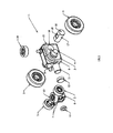
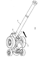
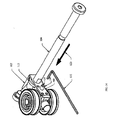
- a first example of a bogey assembly 1 is shown as including a body 2, two main wheels 3 mounted on respective axles 4 and two smaller rollers 5 carried by a pivot arm assembly 6.
- the pivot arm assembly 6 is formed of two lateral sections 7 which extend from a central bearing, which is mounted to a pivot in the form of an axle 8 that projects from a first end 9 of the body 2.
- the assembly 6 is secured to the body 2 in place using a washer 10, which is riveted in place.
- a boss 1 1 is provided on the body 2, beneath the pivot arm assembly 6 and is fitted with a rubber buffer 12.
- the boss 11 and buffer 12 serve as an end of travel stop for the bogey assembly 1.
- the assembly 6 also has a top mounted guide roller 13, which is in alignment with a second guide roller 14 mounted toward a second end 15 of the body 2.
- the second end 15 of the bogey assembly 1 also houses a retainer 16, which is in the form of a pivotal member or axle 17 that extends through a substantially horizontal passage 18 provided in the body 2, arranged transverse to a direction of travel of the bogey assembly 1.
- the retainer 16 includes an internal thread 19 for threaded engagement with a hanger bolt 20, which is illustrated in Figure 2 .
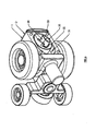
- the hanger bolt 20 is shown as including a threaded shaft 21 with side flats 22 and a bolt head 23, which supports a hinge 24.
- the threaded shaft 21 is engaged with the internal thread 19 and rotated into the retainer 16 until the hanger bolt 20 is at a desired height.
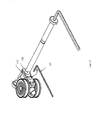
- the hanger bolt 20 can pivot about the retainer 16 in a direction indicated by arrows 25. This serves to substantially reduce moments that might have otherwise applied through the hanger bolt 20 if, for example, the hanger bolt 20 had a fixed connection with the bogey assembly 1.
- the positioning of the retainer 16 toward the second end 15 of the bogey assembly 1 also means any weight load force applied to the hanger bolt 20, such as from a supported door panel or the like (as indicated by arrow 26) is transferred to the rollers 5 through pivot action of the body 2 (as indicated by arrow 27) so that the rollers maintain contact with a track 30, as illustrated in Figures 3 and 4 .
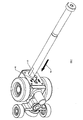
- Figures 3 and 4 show the track 30 as including a top rail section 30A and a lower rail section 30B with a slot 30C to allow passage of the hanger bolt 20 suspended from the bogey assembly 1.
- the top rail section 30A also includes a central channel 30D to receive the guiding rollers 13, 14.
- any downward movement on the hanger bolt 20 will cause the main wheels 3 to firmly engage the lower rail section 30B but will also cause the rollers 5 to be loaded against the top rail section 30A via the pivot arm assembly 6.
- the hanger bolt 20 is able to pivot about the retainer 16 to maintain a generally vertical orientation.
- the pivot arm assembly 6 and its associated axle 8 thereby represents a live axle of the bogey assembly 1 in the sense the pivot arm assembly 6 rotates about a substantially horizontal axis, oriented in a direction of travel of the bogey assembly 1 , to ensure the rollers 5 split the load equally.
- the prior art fixed axle arrangement requires total precision to safeguard against uneven load distribution and wear.
- a second live axle is provided by the retainer 16, which supports the hanger bolt 20.
- the axle 17 also compensates for inaccuracy in the bogey assembly 1. For example, if the rollers 5 are cast too low, the load down the hanger bolt 20 will not be perfectly perpendicular to the bogey assembly 1, which would normally create large bending moments in the hanger bolt 20 and possible fatigue and fracture.
- the live axle 17, however, compensates and automatically adjusts by allowing the retainer 16 to pivot so that the load passes through the hanger bolt 20 without bending. This will, of course, mean the hanger bolt 20 will move fractionally during use but any variation can be taken up by the height adjustment built into the design.
- Pivotal movement of the hanger bolt 20 relative to the bogey assembly 1 does, however, present a problem in relation to locking the hanger bolt 20 at a selected height, to prevent the hanger bolt 20 unscrewing from the body 2 over time.
- a conventional lock-nut to lock the hanger bolt 20 to the body 2 is clearly inappropriate as the pivotal movement of the hanger bolt 20 would be restricted as a result.
- the bogey assembly 1 is provided with a lock mechanism 32, as shown in Figures 5 to 12 .
- the body 2 of the bogey assembly 1 is recessed to provide a housing 31 for the lock mechanism 32.
- the lock mechanism 32 is configured be movable between a locked condition, where the hanger bolt 20 is restrict from rotation about its elongate axis, and an unlocked condition where the hanger bolt 20 may be rotated about its elongate axis.
- the lock mechanism 32 includes a keeper 32A which is arranged to move between an engaged and a free position, the engaged position providing the locked condition and the free position providing the unlocked condition.
- the keeper 32 A is formed as a U-shaped block 33, with flat surfaces 34 confined to fit with flats 22 of the hanger bolt 20. Accordingly, in the engaged condition the flat surfaces 34 of the U-shaped block 33 directly engage with the flats 22 of the hanger bolt 20.
- the U-shaped block 33 provides a slightly elongate housing for the hanger bolt 20 and as such when the keeper 32A is in the engaged position, the U-shaped block 33 restricts the hanger bolt 20 from rotation about its elongate axis but allows the hanger bolt 20 limited movement in the direction of travel of the bogey assembly 1 by pivoting about the retainer 16. During this pivoting it may be appreciated that there will be some limited sliding movement between the flats 22 of the hanger bolt 20 and the flat surfaces 34 of the U- shaped block 33.
- the lock mechanism 32 also has an actuating button 35 which is biased by a spring 36 and which needs to be depressed in order to move the keeper 32A out of engagement with the hanger bolt 20.
- the button 35 has a base 37, received in a bore 38 of the block 33 and a neck 39 which passes through a guide slot, formed in cover plate 39A.
- the button 35 When the keeper 32A is in the engaged position where the lock mechanism 32 is in the locked condition, as illustrated in Figure 6 , the button 35 is spring biased to project through an enlarged aperture 40 in the cover plate 39A. To release the lock mechanism 32, the button 35 needs to firstly be pressed in a direction indicated by arrow 41 in Figure 7 , until shoulders 42 of the button clear the aperture 40, as illustrated in Figure 8 .
- the button 35 is then slid in a direction indicated by arrow 43, as shown in Figure 9 , so that the neck 39 of the button 35 travels along the slot, which draws the keeper 32A out of engagement with the hanger bolt 20 so as to provide the free position where the lock mechanism 32 is in the unlocked condition.
- the hanger bolt 20 may then be rotated in a direction indicated by arrows 44 in Figure 10 , to effect screw threaded axial movement in the directions indicated by arrows 45, into and out of the retainer 16 and hence the bogey assembly 1, as required.
- the hanger bolt 20 When the correct adjustment has been made the hanger bolt 20 is rotated slightly so that the flats 22 are aligned with the surfaces 34 of the keeper 32A as illustrated in Figure 1 1 . From that position, the button 35 is slid back to the original position, as shown in Figure 12 , so that the keeper 32A engages the flats 22 to secure the hanger bolt 20 against any further rotation relative to the bogey assembly 1.
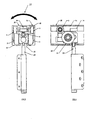
- FIG. 13 Another example of a bogey assembly 101 is shown in Figures 13 to 17 .
- the bogey assembly 101 is shown as including a body 102 with a lock mechanism 103 arranged to engage a hanger bolt 104.
- the body 102 is provided with wheels 105 and rollers 106 for guiding the assembly in an overhead track (not shown) and the lock mechanism 103 serves to fix the hanger bolt 104 in the bogey assembly 101 to thereby lock the bolt head 107 and supported door panel at an appropriate height relative to the track.
- the body 102 is formed from a casting 108 which provides housing 109 for the lock mechanism 103.
- the body 102 also includes a bore 110 for receiving the hanger bolt 104.
- the lock mechanism 103 includes a keeper 1 1 1 which is biased by a spring 1 12 into an engaged position with a locking collar 113.
- the locking collar 1 13 has an external profile with slots 114 which are engaged by the keeper 1 1 1 and an internal throat 1 15 profiled to engage flats 1 16 of the hanger bolt 104.
- a cover plate 1 17 is provided to retain the components of the lock mechanism against the body 102.
- the cover plate 1 17 has an aperture 1 18 to receive a shaft 1 19 of the hanger bolt 104.
- the aperture 118 is aligned with the collar 113 so that, when the hanger bolt 104 is received in the bogey assembly 101, the flats 1 16 are appropriately aligned and fit within the throat 1 15.
- the cover plate 117 also includes opening 118A, through which an actuator button 120 is accessible.
- the actuator button 120 is coupled to the keeper 111 and allows the keeper 111 to be moved between the engaged and free positions.
- the locking collar 113 is free to rotate relative to the body 102, which in turn means the hanger bolt 104 is free to rotate. Accordingly, it may be appreciated the lock mechanism 103 provides a locked condition when the keeper 111 is the engaged condition and an unlocked condition when the keeper 111 is the free position.
- the keeper 111 is biased into the engaged position by the spring 12 so that when adjustment has been completed, the keeper 111 will automatically re-engage the collar 113, as soon as the flats 1 16 of the hanger bolt 104 are at right angles to the keeper 111, so that the keeper 111 can lock into one of the slots 1 14.
- the lock mechanism 103 is in the locked condition, where the locking collar 113 is engaged by the keeper 111 and the hanger bolt 104 is locked against any rotation relative to the body 102 of the bogey assembly 101.
- the button 120 needs to firstly be depressed. This may be done by hand, using a finger or the like. Alternatively, a key 121 may be inserted in a recess 122 of the button, as illustrated, and pressed in a direction indicated by arrow 123. While the button 120 is pressed inwardly of the body 102, the hanger bolt 104 may be manually rotated for adjustment or a spanner key 124 can instead be inserted in the bolt head 107, as illustrated in Figure 15 .
- the lock mechanisms 32, 103 provide a convenient and simple means to securely lock the hanger bolt 20, 104 after appropriate height adjustment relative to the bogey assembly 1, 101.
- the lock mechanisms 32, 103 have no free parts that might otherwise be dropped or lost and can be manually disengaged for further adjustment, if required, without the need for specialised tools.
- the mechanisms 32, 103 are also housed within the body 4, 102 of the bogey assemblies 1, 101, to minimise aesthetic impact. Since the body assemblies 1, 101 are themselves located within an overhead track during use the entire height adjustment and lock mechanism will also be hidden from view.
- a bogey assembly for supporting a hanger bolt including a body for supporting the hanger bolt when in use and a lock mechanism operatively mounted to the body, the lock mechanism being operable so as to be able to adopt a locked condition, where the hanger bolt is restricted from movement relative the body, and a unlocked condition where the hanger bolt can be moved relative to the body.
- Numbered clause 2 The bogey assembly according to numbered clause 1, wherein when the lock mechanism is in the locked condition the hanger bolt is restricted from rotational movement relative to the body.
- Numbered clause 4 The bogey assembly according to any one of numbered clauses 1 to 3, wherein the lock mechanism includes a keeper which is moveable between a free position, in which the lock mechanism is in the unlocked condition, and an engaged position, in which the lock mechanism is in the locked condition.
- Numbered clause 7 The bogey assembly of numbered clause 6, wherein the keeper slides laterally of the hanger bolt to engage the side flats.
- Numbered clause 8 The bogey assembly according to numbered clause 4, wherein the hanger bolt includes a collar associated therewith and the keeper is arranged to restrict movement of the collar when in the engaged position.
- Numbered clause 9 The bogey assembly of numbered clause 8, wherein the collar includes a throat which is profiled to key with side flats of the hanger bolt and an external profile to engage with the keeper to prevent rotation of the hanger bolt when in the engaged position.
- Numbered clause 10 The bogey assembly according to any one of numbered clauses 4 to 9, wherein the keeper is retained in the engaged position under bias.
- Numbered clause 11 The bogey assembly according to any one of numbered clauses 4 to 10, wherein the lock mechanism includes an actuator button to move the keeper between the free and the engaged positions.
- a bogey assembly for supporting a hanger bolt when in use, the bogey assembly including a body through which a retainer is mounted, the retainer being internally threaded for engagement with a corresponding thread on the hanger bolt and wherein the retainer is able to pivot relative the body of the bogey so that the hanger bolt is able to swing relative to the body of the bogey.
- Numbered clause 15 The bogey assembly of numbered clause 14, wherein the retainer is arranged to extend substantially horizontally in a transverse direction relative to a direction of travel of the bogey assembly.
- Numbered clause 18 The bogey assembly of numbered clause 17, wherein the retainer is provided towards a second end of the body and the bogey assembly further includes side wheels, to support the body intermediate the first and second ends.
- Numbered clause 19 The bogey assembly of numbered clause 18, wherein the bogey assembly further includes a guide element located on top of the body for receipt in a track through which the bogey assembly travels, the element being arranged to guide the bogey assembly during travel along the track.
- a bogey assembly including a body with an arm supporting two laterally spaced rollers, the arm being coupled to a pivot located on the body so as to rotate about an axis oriented toward a direction of travel of the bogey assembly.
- the bogey assembly according to any one of numbered clauses 14 to 23, further including a lock mechanism housed by the body, the lock mechanism being operable so as to be able to adopt a locked condition, where the hanger bolt is restricted from movement relative the body, and an unlocked condition where the hanger bolt can be moved relative to the body.
- Numbered clause 26 The bogey assembly according to numbered clauses 24 and 25, wherein the lock mechanism includes a keeper which is moveable between a free position, in which the lock mechanism is in the unlocked condition, and an engaged position in which the lock mechanism is in the locked condition.
- Numbered clause 27 The bogey assembly of numbered clause 26, wherein in the free position the hanger bolt is free to rotate for adjustment in or out of the retainer, and the engaged position the hanger bolt is restricted in rotation about its elongate axis.
- Numbered clause 28 The bogey assembly of numbered clause 27, wherein in the engaged position the hanger bolt is able to pivot about the retainer.
Landscapes
- Engineering & Computer Science (AREA)
- Mechanical Engineering (AREA)
- Support Devices For Sliding Doors (AREA)
- Chain Conveyers (AREA)
- Supports For Pipes And Cables (AREA)
- Holders For Apparel And Elements Relating To Apparel (AREA)
Priority Applications (1)
| Application Number | Priority Date | Filing Date | Title |
|---|---|---|---|
| PL12187697T PL2546440T3 (pl) | 2009-07-31 | 2010-07-29 | Zespół wózka |
Applications Claiming Priority (5)
| Application Number | Priority Date | Filing Date | Title |
|---|---|---|---|
| AU2009903608A AU2009903608A0 (en) | 2009-07-31 | Bogey assembly | |
| AU2009906264A AU2009906264A0 (en) | 2009-12-23 | Carriage assembly with a lock mechanism | |
| AU2009251170A AU2009251170B1 (en) | 2009-07-31 | 2009-12-23 | Bogey |
| EP10803741.7A EP2459828B1 (de) | 2009-07-31 | 2010-07-29 | Laufrollenanordnung |
| PCT/AU2010/000963 WO2011011832A1 (en) | 2009-07-31 | 2010-07-29 | Bogey assembly |
Related Parent Applications (3)
| Application Number | Title | Priority Date | Filing Date |
|---|---|---|---|
| EP10803741.7 Division | 2010-07-29 | ||
| EP10803741.7A Division EP2459828B1 (de) | 2009-07-31 | 2010-07-29 | Laufrollenanordnung |
| EP10803741.7A Division-Into EP2459828B1 (de) | 2009-07-31 | 2010-07-29 | Laufrollenanordnung |
Publications (3)
| Publication Number | Publication Date |
|---|---|
| EP2546440A2 true EP2546440A2 (de) | 2013-01-16 |
| EP2546440A3 EP2546440A3 (de) | 2014-05-07 |
| EP2546440B1 EP2546440B1 (de) | 2019-04-24 |
Family
ID=43528642
Family Applications (3)
| Application Number | Title | Priority Date | Filing Date |
|---|---|---|---|
| EP10803741.7A Not-in-force EP2459828B1 (de) | 2009-07-31 | 2010-07-29 | Laufrollenanordnung |
| EP14172627.3A Not-in-force EP2781677B1 (de) | 2009-07-31 | 2010-07-29 | Laufrollenanordnung |
| EP12187697.3A Not-in-force EP2546440B1 (de) | 2009-07-31 | 2010-07-29 | Laufrollenanordnung |
Family Applications Before (2)
| Application Number | Title | Priority Date | Filing Date |
|---|---|---|---|
| EP10803741.7A Not-in-force EP2459828B1 (de) | 2009-07-31 | 2010-07-29 | Laufrollenanordnung |
| EP14172627.3A Not-in-force EP2781677B1 (de) | 2009-07-31 | 2010-07-29 | Laufrollenanordnung |
Country Status (5)
| Country | Link |
|---|---|
| US (2) | US8677564B2 (de) |
| EP (3) | EP2459828B1 (de) |
| AU (1) | AU2010278677B2 (de) |
| PL (2) | PL2546440T3 (de) |
| WO (1) | WO2011011832A1 (de) |
Families Citing this family (19)
| Publication number | Priority date | Publication date | Assignee | Title |
|---|---|---|---|---|
| AU2013203767B2 (en) * | 2012-05-29 | 2016-07-07 | Ciilock Engineering Pty Ltd | Connection arrangements, pivots and mechanisms |
| GB2522141B (en) * | 2012-10-17 | 2020-08-12 | Centor Design Pty Ltd | A hanger hinge |
| US9032588B2 (en) * | 2012-12-28 | 2015-05-19 | Nien Made Enterprise Co., Ltd. | Covering of building opening |
| US8869351B2 (en) * | 2013-03-07 | 2014-10-28 | Nien Made Enterprise Co., Ltd. | Detachable hanger for covering of building's opening |
| US20170231413A1 (en) * | 2014-08-19 | 2017-08-17 | Silent Gliss International Ag | Suspension Unit for a Curtain Device |
| AU2015323358A1 (en) | 2014-09-22 | 2017-04-13 | Allegion (Australia) Pty Ltd. | Pivot block |
| US10294704B2 (en) * | 2014-10-10 | 2019-05-21 | Mammoth Industries Pty Ltd | Adjustable hinge and method of adjustment |
| US9689185B2 (en) | 2015-09-10 | 2017-06-27 | Caldwell Manufacturing Company North America, LLC | Adjustable hinge for vertically hanging panel |
| US10661839B2 (en) * | 2016-12-05 | 2020-05-26 | Cnh Industrial America Llc | Roller assembly for a hood actuation system |
| US10604930B2 (en) * | 2017-02-15 | 2020-03-31 | Hunter Douglas Inc. | Friction adjustment member for architectural covering |
| US9976329B1 (en) | 2017-05-05 | 2018-05-22 | Caldwell Manufacturing Company North America, LLC | Adjustable carriage assembly for suspending a panel |
| IT201700084318A1 (it) * | 2017-07-24 | 2019-01-24 | Bortoluzzi Sistemi Spa | “dispositivo anti-deragliamento per ante scorrevoli di mobili” |
| AU2017279738B1 (en) * | 2017-12-21 | 2018-08-30 | Assa Abloy New Zealand Limited | Multi panel components |
| AT521140B1 (de) * | 2018-11-13 | 2019-11-15 | Blum Gmbh Julius | Führungsschlitten zur verfahrbaren Lagerung eines Möbelteiles |
| AT521373B1 (de) * | 2018-11-13 | 2020-01-15 | Blum Gmbh Julius | Anordnung zur Führung einer Schiebetür |
| US11486177B2 (en) | 2019-06-06 | 2022-11-01 | Endura Products, Llc | Continuous locking hinge assemblies and folding door assemblies including the same |
| AT523327A1 (de) * | 2019-12-19 | 2021-07-15 | Blum Gmbh Julius | Führungsvorrichtung zur Führung eines Möbelteils |
| USD1057552S1 (en) * | 2020-09-15 | 2025-01-14 | Assa Abloy New Zealand Limited | Hanger for a folding panel system |
| US12523086B2 (en) | 2023-01-27 | 2026-01-13 | Endura Products, Llc | Continuous locking hinge assemblies and folding door assemblies including the same |
Family Cites Families (23)
| Publication number | Priority date | Publication date | Assignee | Title |
|---|---|---|---|---|
| US1931796A (en) | 1930-12-08 | 1933-10-24 | Richards Wilcox Mfg Co | Door hanger |
| GB659625A (en) * | 1949-02-15 | 1951-10-24 | Beckett Laycock & Watkinson | Improvements in or relating to sliding doors |
| US2761172A (en) * | 1952-11-14 | 1956-09-04 | Washington Steel Products Inc | Adjustable hanger for sliding doors |
| US2957197A (en) * | 1958-08-22 | 1960-10-25 | Jr Leonard E Johnson | Door hanger |
| US3829929A (en) * | 1971-05-07 | 1974-08-20 | Lawrence Brothers | Folding door hanger with emergency release |
| US3757384A (en) * | 1972-02-03 | 1973-09-11 | Lawrence Brothers | Hanger device |
| GB1405931A (en) * | 1972-05-26 | 1975-09-10 | Henderson P C Ltd | Hangers for sliding doors |
| US4750237A (en) * | 1986-11-03 | 1988-06-14 | National Manufacturing Co. | Trolley assembly for a pocket door |
| JPS6433060A (en) | 1987-07-29 | 1989-02-02 | Kitagawa Iron Works Co | Ceramics for internal chill |
| US5035025A (en) * | 1990-01-23 | 1991-07-30 | Combo Corporation | Trundle trolley for a sliding door track assembly |
| CH691073A5 (de) * | 1995-07-21 | 2001-04-12 | Hawa Ag | Puffervorrichtung. |
| AU738739B2 (en) * | 1998-09-04 | 2001-09-27 | Centor Products Pty Ltd | Trailing carrier for folding panels |
| DE19860122C2 (de) * | 1998-12-23 | 2000-11-23 | Agta Record Ag Fehraltorf | Laufwagen für einen verfahrbaren Gegenstand, insbesondere für eine automatische Schiebetür oder ein automatisches Schiebetor mit zumindest einer Schiebetür oder einem Schiebetor |
| US6209171B1 (en) * | 1999-10-01 | 2001-04-03 | The Stanley Works | Movable door mounting assembly |
| US6463625B2 (en) * | 2000-12-20 | 2002-10-15 | Richards-Wilcox, Inc. | Door truck with a one piece frame and low friction wheels |
| AUPR480701A0 (en) | 2001-05-04 | 2001-05-31 | Centor Products Pty Ltd | A lockable carrier hinge assembly |
| US6983512B2 (en) * | 2002-07-23 | 2006-01-10 | Masco Corporation | Movable door mounting assembly with trolley locking structure |
| US7117559B1 (en) * | 2004-08-14 | 2006-10-10 | David Barber | Support system for pocket doors |
| DE102004062764A1 (de) * | 2004-12-21 | 2006-06-29 | Geze Gmbh | Rollenwagen |
| JP2007315106A (ja) | 2006-05-26 | 2007-12-06 | Matsushita Electric Works Ltd | 引戸のランナー装置 |
| JP5076825B2 (ja) * | 2006-12-12 | 2012-11-21 | 中西金属工業株式会社 | 吊車装置 |
| JP5134344B2 (ja) * | 2007-11-28 | 2013-01-30 | 小松ウオール工業株式会社 | 吊りボルトの緩み止め装置 |
| EP2218858B1 (de) * | 2009-02-15 | 2013-10-16 | Hawa Ag | Laufwerk für ein Trennelement, Trennelement und Vorrichtung |
-
2010
- 2010-07-29 US US13/388,252 patent/US8677564B2/en not_active Expired - Fee Related
- 2010-07-29 EP EP10803741.7A patent/EP2459828B1/de not_active Not-in-force
- 2010-07-29 EP EP14172627.3A patent/EP2781677B1/de not_active Not-in-force
- 2010-07-29 EP EP12187697.3A patent/EP2546440B1/de not_active Not-in-force
- 2010-07-29 PL PL12187697T patent/PL2546440T3/pl unknown
- 2010-07-29 WO PCT/AU2010/000963 patent/WO2011011832A1/en not_active Ceased
- 2010-07-29 PL PL14172627T patent/PL2781677T3/pl unknown
- 2010-07-29 AU AU2010278677A patent/AU2010278677B2/en not_active Ceased
-
2014
- 2014-02-11 US US14/177,834 patent/US9032589B2/en not_active Expired - Fee Related
Non-Patent Citations (1)
| Title |
|---|
| None |
Also Published As
| Publication number | Publication date |
|---|---|
| EP2781677A2 (de) | 2014-09-24 |
| AU2010278677A1 (en) | 2012-02-16 |
| US8677564B2 (en) | 2014-03-25 |
| EP2781677B1 (de) | 2019-05-01 |
| EP2546440B1 (de) | 2019-04-24 |
| US9032589B2 (en) | 2015-05-19 |
| EP2459828A4 (de) | 2014-05-14 |
| WO2011011832A1 (en) | 2011-02-03 |
| US20140157549A1 (en) | 2014-06-12 |
| PL2781677T3 (pl) | 2020-01-31 |
| US20120186046A1 (en) | 2012-07-26 |
| AU2010278677B2 (en) | 2014-10-23 |
| EP2459828A1 (de) | 2012-06-06 |
| PL2546440T3 (pl) | 2020-01-31 |
| EP2546440A3 (de) | 2014-05-07 |
| EP2459828B1 (de) | 2015-11-25 |
| EP2781677A3 (de) | 2015-01-14 |
Similar Documents
| Publication | Publication Date | Title |
|---|---|---|
| EP2546440A2 (de) | Laufrollenanordnung | |
| US9157265B2 (en) | Bogey | |
| US7861475B2 (en) | Wall panel system including a pivot lock | |
| CN210343038U (zh) | 面板托架悬挂器和多面板系统 | |
| US8646815B2 (en) | Gate latch | |
| CN101684704B (zh) | 用于门的翼扇的固定装置 | |
| EP2611980B1 (de) | Führungsanordnung | |
| CN108699873B (zh) | 用于连接可滑动且可翻转的扇的装配总成 | |
| US5450651A (en) | End cap locking overhead mounted door holder assembly | |
| US20150000082A1 (en) | Hinge and method of adjustment | |
| DE102008000048A1 (de) | Eckband eines Ecklagers | |
| CA2351190C (en) | Pivot connection adjustment assembly | |
| CN108150041B (zh) | 一种家具折叠门的自动拆装机构 | |
| EP0649961A1 (de) | Türhalter | |
| CN101223328A (zh) | 铰链 | |
| US20070050947A1 (en) | Two Bar Stays and Associated Methods | |
| AU2009251170B1 (en) | Bogey | |
| EP0943772A2 (de) | Struktur zur Lagerung von Schiebetüren | |
| AU2014221269B2 (en) | Bogey assembly | |
| AU2012201223B2 (en) | Bogey assembly | |
| EP2096243B1 (de) | Verschlussvorrichtung für Doppeltüren oder -fenster | |
| JP6931377B2 (ja) | 可動式ホーム柵および治具 | |
| KR200269331Y1 (ko) | 창문용 호차 | |
| JP3254426B2 (ja) | 扉用走行装置 | |
| HK1142646B (en) | Securing device for a door leaf |
Legal Events
| Date | Code | Title | Description |
|---|---|---|---|
| PUAI | Public reference made under article 153(3) epc to a published international application that has entered the european phase |
Free format text: ORIGINAL CODE: 0009012 |
|
| AC | Divisional application: reference to earlier application |
Ref document number: 2459828 Country of ref document: EP Kind code of ref document: P |
|
| AK | Designated contracting states |
Kind code of ref document: A2 Designated state(s): AL AT BE BG CH CY CZ DE DK EE ES FI FR GB GR HR HU IE IS IT LI LT LU LV MC MK MT NL NO PL PT RO SE SI SK SM TR |
|
| PUAL | Search report despatched |
Free format text: ORIGINAL CODE: 0009013 |
|
| AK | Designated contracting states |
Kind code of ref document: A3 Designated state(s): AL AT BE BG CH CY CZ DE DK EE ES FI FR GB GR HR HU IE IS IT LI LT LU LV MC MK MT NL NO PL PT RO SE SI SK SM TR |
|
| RIC1 | Information provided on ipc code assigned before grant |
Ipc: E05D 15/06 20060101AFI20140331BHEP Ipc: E05D 15/26 20060101ALI20140331BHEP |
|
| 17P | Request for examination filed |
Effective date: 20141024 |
|
| RBV | Designated contracting states (corrected) |
Designated state(s): AL AT BE BG CH CY CZ DE DK EE ES FI FR GB GR HR HU IE IS IT LI LT LU LV MC MK MT NL NO PL PT RO SE SI SK SM TR |
|
| RAP1 | Party data changed (applicant data changed or rights of an application transferred) |
Owner name: ALLEGION (UK) LIMITED |
|
| STAA | Information on the status of an ep patent application or granted ep patent |
Free format text: STATUS: EXAMINATION IS IN PROGRESS |
|
| 17Q | First examination report despatched |
Effective date: 20161128 |
|
| GRAP | Despatch of communication of intention to grant a patent |
Free format text: ORIGINAL CODE: EPIDOSNIGR1 |
|
| STAA | Information on the status of an ep patent application or granted ep patent |
Free format text: STATUS: GRANT OF PATENT IS INTENDED |
|
| INTG | Intention to grant announced |
Effective date: 20181113 |
|
| RAP1 | Party data changed (applicant data changed or rights of an application transferred) |
Owner name: ALLEGION (UK) LIMITED |
|
| GRAS | Grant fee paid |
Free format text: ORIGINAL CODE: EPIDOSNIGR3 |
|
| GRAA | (expected) grant |
Free format text: ORIGINAL CODE: 0009210 |
|
| STAA | Information on the status of an ep patent application or granted ep patent |
Free format text: STATUS: THE PATENT HAS BEEN GRANTED |
|
| AC | Divisional application: reference to earlier application |
Ref document number: 2459828 Country of ref document: EP Kind code of ref document: P |
|
| AK | Designated contracting states |
Kind code of ref document: B1 Designated state(s): AL AT BE BG CH CY CZ DE DK EE ES FI FR GB GR HR HU IE IS IT LI LT LU LV MC MK MT NL NO PL PT RO SE SI SK SM TR |
|
| REG | Reference to a national code |
Ref country code: GB Ref legal event code: FG4D |
|
| REG | Reference to a national code |
Ref country code: CH Ref legal event code: EP |
|
| REG | Reference to a national code |
Ref country code: AT Ref legal event code: REF Ref document number: 1124364 Country of ref document: AT Kind code of ref document: T Effective date: 20190515 Ref country code: IE Ref legal event code: FG4D |
|
| REG | Reference to a national code |
Ref country code: DE Ref legal event code: R096 Ref document number: 602010058499 Country of ref document: DE |
|
| REG | Reference to a national code |
Ref country code: NL Ref legal event code: MP Effective date: 20190424 |
|
| REG | Reference to a national code |
Ref country code: LT Ref legal event code: MG4D |
|
| PG25 | Lapsed in a contracting state [announced via postgrant information from national office to epo] |
Ref country code: NL Free format text: LAPSE BECAUSE OF FAILURE TO SUBMIT A TRANSLATION OF THE DESCRIPTION OR TO PAY THE FEE WITHIN THE PRESCRIBED TIME-LIMIT Effective date: 20190424 |
|
| PG25 | Lapsed in a contracting state [announced via postgrant information from national office to epo] |
Ref country code: ES Free format text: LAPSE BECAUSE OF FAILURE TO SUBMIT A TRANSLATION OF THE DESCRIPTION OR TO PAY THE FEE WITHIN THE PRESCRIBED TIME-LIMIT Effective date: 20190424 Ref country code: HR Free format text: LAPSE BECAUSE OF FAILURE TO SUBMIT A TRANSLATION OF THE DESCRIPTION OR TO PAY THE FEE WITHIN THE PRESCRIBED TIME-LIMIT Effective date: 20190424 Ref country code: LT Free format text: LAPSE BECAUSE OF FAILURE TO SUBMIT A TRANSLATION OF THE DESCRIPTION OR TO PAY THE FEE WITHIN THE PRESCRIBED TIME-LIMIT Effective date: 20190424 Ref country code: PT Free format text: LAPSE BECAUSE OF FAILURE TO SUBMIT A TRANSLATION OF THE DESCRIPTION OR TO PAY THE FEE WITHIN THE PRESCRIBED TIME-LIMIT Effective date: 20190824 Ref country code: FI Free format text: LAPSE BECAUSE OF FAILURE TO SUBMIT A TRANSLATION OF THE DESCRIPTION OR TO PAY THE FEE WITHIN THE PRESCRIBED TIME-LIMIT Effective date: 20190424 Ref country code: NO Free format text: LAPSE BECAUSE OF FAILURE TO SUBMIT A TRANSLATION OF THE DESCRIPTION OR TO PAY THE FEE WITHIN THE PRESCRIBED TIME-LIMIT Effective date: 20190724 Ref country code: SE Free format text: LAPSE BECAUSE OF FAILURE TO SUBMIT A TRANSLATION OF THE DESCRIPTION OR TO PAY THE FEE WITHIN THE PRESCRIBED TIME-LIMIT Effective date: 20190424 Ref country code: AL Free format text: LAPSE BECAUSE OF FAILURE TO SUBMIT A TRANSLATION OF THE DESCRIPTION OR TO PAY THE FEE WITHIN THE PRESCRIBED TIME-LIMIT Effective date: 20190424 |
|
| PG25 | Lapsed in a contracting state [announced via postgrant information from national office to epo] |
Ref country code: LV Free format text: LAPSE BECAUSE OF FAILURE TO SUBMIT A TRANSLATION OF THE DESCRIPTION OR TO PAY THE FEE WITHIN THE PRESCRIBED TIME-LIMIT Effective date: 20190424 Ref country code: GR Free format text: LAPSE BECAUSE OF FAILURE TO SUBMIT A TRANSLATION OF THE DESCRIPTION OR TO PAY THE FEE WITHIN THE PRESCRIBED TIME-LIMIT Effective date: 20190725 Ref country code: BG Free format text: LAPSE BECAUSE OF FAILURE TO SUBMIT A TRANSLATION OF THE DESCRIPTION OR TO PAY THE FEE WITHIN THE PRESCRIBED TIME-LIMIT Effective date: 20190724 |
|
| REG | Reference to a national code |
Ref country code: AT Ref legal event code: MK05 Ref document number: 1124364 Country of ref document: AT Kind code of ref document: T Effective date: 20190424 |
|
| PG25 | Lapsed in a contracting state [announced via postgrant information from national office to epo] |
Ref country code: IS Free format text: LAPSE BECAUSE OF FAILURE TO SUBMIT A TRANSLATION OF THE DESCRIPTION OR TO PAY THE FEE WITHIN THE PRESCRIBED TIME-LIMIT Effective date: 20190824 |
|
| PGFP | Annual fee paid to national office [announced via postgrant information from national office to epo] |
Ref country code: GB Payment date: 20190703 Year of fee payment: 10 |
|
| REG | Reference to a national code |
Ref country code: DE Ref legal event code: R097 Ref document number: 602010058499 Country of ref document: DE |
|
| PG25 | Lapsed in a contracting state [announced via postgrant information from national office to epo] |
Ref country code: CZ Free format text: LAPSE BECAUSE OF FAILURE TO SUBMIT A TRANSLATION OF THE DESCRIPTION OR TO PAY THE FEE WITHIN THE PRESCRIBED TIME-LIMIT Effective date: 20190424 Ref country code: RO Free format text: LAPSE BECAUSE OF FAILURE TO SUBMIT A TRANSLATION OF THE DESCRIPTION OR TO PAY THE FEE WITHIN THE PRESCRIBED TIME-LIMIT Effective date: 20190424 Ref country code: EE Free format text: LAPSE BECAUSE OF FAILURE TO SUBMIT A TRANSLATION OF THE DESCRIPTION OR TO PAY THE FEE WITHIN THE PRESCRIBED TIME-LIMIT Effective date: 20190424 Ref country code: SK Free format text: LAPSE BECAUSE OF FAILURE TO SUBMIT A TRANSLATION OF THE DESCRIPTION OR TO PAY THE FEE WITHIN THE PRESCRIBED TIME-LIMIT Effective date: 20190424 Ref country code: AT Free format text: LAPSE BECAUSE OF FAILURE TO SUBMIT A TRANSLATION OF THE DESCRIPTION OR TO PAY THE FEE WITHIN THE PRESCRIBED TIME-LIMIT Effective date: 20190424 Ref country code: DK Free format text: LAPSE BECAUSE OF FAILURE TO SUBMIT A TRANSLATION OF THE DESCRIPTION OR TO PAY THE FEE WITHIN THE PRESCRIBED TIME-LIMIT Effective date: 20190424 |
|
| REG | Reference to a national code |
Ref country code: DE Ref legal event code: R119 Ref document number: 602010058499 Country of ref document: DE |
|
| PG25 | Lapsed in a contracting state [announced via postgrant information from national office to epo] |
Ref country code: IT Free format text: LAPSE BECAUSE OF FAILURE TO SUBMIT A TRANSLATION OF THE DESCRIPTION OR TO PAY THE FEE WITHIN THE PRESCRIBED TIME-LIMIT Effective date: 20190424 Ref country code: SM Free format text: LAPSE BECAUSE OF FAILURE TO SUBMIT A TRANSLATION OF THE DESCRIPTION OR TO PAY THE FEE WITHIN THE PRESCRIBED TIME-LIMIT Effective date: 20190424 Ref country code: MC Free format text: LAPSE BECAUSE OF FAILURE TO SUBMIT A TRANSLATION OF THE DESCRIPTION OR TO PAY THE FEE WITHIN THE PRESCRIBED TIME-LIMIT Effective date: 20190424 |
|
| PGFP | Annual fee paid to national office [announced via postgrant information from national office to epo] |
Ref country code: PL Payment date: 20190710 Year of fee payment: 10 |
|
| PLBE | No opposition filed within time limit |
Free format text: ORIGINAL CODE: 0009261 |
|
| REG | Reference to a national code |
Ref country code: CH Ref legal event code: PL |
|
| STAA | Information on the status of an ep patent application or granted ep patent |
Free format text: STATUS: NO OPPOSITION FILED WITHIN TIME LIMIT |
|
| PG25 | Lapsed in a contracting state [announced via postgrant information from national office to epo] |
Ref country code: TR Free format text: LAPSE BECAUSE OF FAILURE TO SUBMIT A TRANSLATION OF THE DESCRIPTION OR TO PAY THE FEE WITHIN THE PRESCRIBED TIME-LIMIT Effective date: 20190424 |
|
| 26N | No opposition filed |
Effective date: 20200127 |
|
| REG | Reference to a national code |
Ref country code: BE Ref legal event code: MM Effective date: 20190731 |
|
| PG25 | Lapsed in a contracting state [announced via postgrant information from national office to epo] |
Ref country code: DE Free format text: LAPSE BECAUSE OF NON-PAYMENT OF DUE FEES Effective date: 20200201 |
|
| PG25 | Lapsed in a contracting state [announced via postgrant information from national office to epo] |
Ref country code: SI Free format text: LAPSE BECAUSE OF FAILURE TO SUBMIT A TRANSLATION OF THE DESCRIPTION OR TO PAY THE FEE WITHIN THE PRESCRIBED TIME-LIMIT Effective date: 20190424 Ref country code: LI Free format text: LAPSE BECAUSE OF NON-PAYMENT OF DUE FEES Effective date: 20190731 Ref country code: CH Free format text: LAPSE BECAUSE OF NON-PAYMENT OF DUE FEES Effective date: 20190731 Ref country code: LU Free format text: LAPSE BECAUSE OF NON-PAYMENT OF DUE FEES Effective date: 20190729 Ref country code: BE Free format text: LAPSE BECAUSE OF NON-PAYMENT OF DUE FEES Effective date: 20190731 |
|
| PG25 | Lapsed in a contracting state [announced via postgrant information from national office to epo] |
Ref country code: FR Free format text: LAPSE BECAUSE OF NON-PAYMENT OF DUE FEES Effective date: 20190731 |
|
| PG25 | Lapsed in a contracting state [announced via postgrant information from national office to epo] |
Ref country code: IE Free format text: LAPSE BECAUSE OF NON-PAYMENT OF DUE FEES Effective date: 20190729 |
|
| GBPC | Gb: european patent ceased through non-payment of renewal fee |
Effective date: 20200729 |
|
| PG25 | Lapsed in a contracting state [announced via postgrant information from national office to epo] |
Ref country code: GB Free format text: LAPSE BECAUSE OF NON-PAYMENT OF DUE FEES Effective date: 20200729 |
|
| PG25 | Lapsed in a contracting state [announced via postgrant information from national office to epo] |
Ref country code: CY Free format text: LAPSE BECAUSE OF FAILURE TO SUBMIT A TRANSLATION OF THE DESCRIPTION OR TO PAY THE FEE WITHIN THE PRESCRIBED TIME-LIMIT Effective date: 20190424 |
|
| PG25 | Lapsed in a contracting state [announced via postgrant information from national office to epo] |
Ref country code: HU Free format text: LAPSE BECAUSE OF FAILURE TO SUBMIT A TRANSLATION OF THE DESCRIPTION OR TO PAY THE FEE WITHIN THE PRESCRIBED TIME-LIMIT; INVALID AB INITIO Effective date: 20100729 Ref country code: MT Free format text: LAPSE BECAUSE OF FAILURE TO SUBMIT A TRANSLATION OF THE DESCRIPTION OR TO PAY THE FEE WITHIN THE PRESCRIBED TIME-LIMIT Effective date: 20190424 |
|
| PG25 | Lapsed in a contracting state [announced via postgrant information from national office to epo] |
Ref country code: MK Free format text: LAPSE BECAUSE OF FAILURE TO SUBMIT A TRANSLATION OF THE DESCRIPTION OR TO PAY THE FEE WITHIN THE PRESCRIBED TIME-LIMIT Effective date: 20190424 |
|
| PG25 | Lapsed in a contracting state [announced via postgrant information from national office to epo] |
Ref country code: PL Free format text: LAPSE BECAUSE OF NON-PAYMENT OF DUE FEES Effective date: 20200729 |