EP2546447A2 - Betätigungsmechanismus für eine Schiebetür eines Kraftfahrzeugs - Google Patents
Betätigungsmechanismus für eine Schiebetür eines Kraftfahrzeugs Download PDFInfo
- Publication number
- EP2546447A2 EP2546447A2 EP20120275073 EP12275073A EP2546447A2 EP 2546447 A2 EP2546447 A2 EP 2546447A2 EP 20120275073 EP20120275073 EP 20120275073 EP 12275073 A EP12275073 A EP 12275073A EP 2546447 A2 EP2546447 A2 EP 2546447A2
- Authority
- EP
- European Patent Office
- Prior art keywords
- door
- cable
- guide
- motor vehicle
- attached
- Prior art date
- Legal status (The legal status is an assumption and is not a legal conclusion. Google has not performed a legal analysis and makes no representation as to the accuracy of the status listed.)
- Granted
Links
Images


Classifications
-
- E—FIXED CONSTRUCTIONS
- E05—LOCKS; KEYS; WINDOW OR DOOR FITTINGS; SAFES
- E05F—DEVICES FOR MOVING WINGS INTO OPEN OR CLOSED POSITION; CHECKS FOR WINGS; WING FITTINGS NOT OTHERWISE PROVIDED FOR, CONCERNED WITH THE FUNCTIONING OF THE WING
- E05F15/00—Power-operated mechanisms for wings
- E05F15/60—Power-operated mechanisms for wings using electrical actuators
- E05F15/603—Power-operated mechanisms for wings using electrical actuators using rotary electromotors
- E05F15/632—Power-operated mechanisms for wings using electrical actuators using rotary electromotors for horizontally-sliding wings
- E05F15/643—Power-operated mechanisms for wings using electrical actuators using rotary electromotors for horizontally-sliding wings operated by flexible elongated pulling elements, e.g. belts, chains or cables
-
- B—PERFORMING OPERATIONS; TRANSPORTING
- B60—VEHICLES IN GENERAL
- B60J—WINDOWS, WINDSCREENS, NON-FIXED ROOFS, DOORS, OR SIMILAR DEVICES FOR VEHICLES; REMOVABLE EXTERNAL PROTECTIVE COVERINGS SPECIALLY ADAPTED FOR VEHICLES
- B60J5/00—Doors
- B60J5/04—Doors arranged at the vehicle sides
- B60J5/06—Doors arranged at the vehicle sides slidable; foldable
-
- E—FIXED CONSTRUCTIONS
- E05—LOCKS; KEYS; WINDOW OR DOOR FITTINGS; SAFES
- E05F—DEVICES FOR MOVING WINGS INTO OPEN OR CLOSED POSITION; CHECKS FOR WINGS; WING FITTINGS NOT OTHERWISE PROVIDED FOR, CONCERNED WITH THE FUNCTIONING OF THE WING
- E05F15/00—Power-operated mechanisms for wings
- E05F15/60—Power-operated mechanisms for wings using electrical actuators
- E05F15/603—Power-operated mechanisms for wings using electrical actuators using rotary electromotors
- E05F15/632—Power-operated mechanisms for wings using electrical actuators using rotary electromotors for horizontally-sliding wings
- E05F15/643—Power-operated mechanisms for wings using electrical actuators using rotary electromotors for horizontally-sliding wings operated by flexible elongated pulling elements, e.g. belts, chains or cables
- E05F15/646—Power-operated mechanisms for wings using electrical actuators using rotary electromotors for horizontally-sliding wings operated by flexible elongated pulling elements, e.g. belts, chains or cables allowing or involving a secondary movement of the wing, e.g. rotational or transversal
-
- E—FIXED CONSTRUCTIONS
- E05—LOCKS; KEYS; WINDOW OR DOOR FITTINGS; SAFES
- E05Y—INDEXING SCHEME ASSOCIATED WITH SUBCLASSES E05D AND E05F, RELATING TO CONSTRUCTION ELEMENTS, ELECTRIC CONTROL, POWER SUPPLY, POWER SIGNAL OR TRANSMISSION, USER INTERFACES, MOUNTING OR COUPLING, DETAILS, ACCESSORIES, AUXILIARY OPERATIONS NOT OTHERWISE PROVIDED FOR, APPLICATION THEREOF
- E05Y2600/00—Mounting or coupling arrangements for elements provided for in this subclass
- E05Y2600/40—Mounting location; Visibility of the elements
- E05Y2600/46—Mounting location; Visibility of the elements in or on the wing
-
- E—FIXED CONSTRUCTIONS
- E05—LOCKS; KEYS; WINDOW OR DOOR FITTINGS; SAFES
- E05Y—INDEXING SCHEME ASSOCIATED WITH SUBCLASSES E05D AND E05F, RELATING TO CONSTRUCTION ELEMENTS, ELECTRIC CONTROL, POWER SUPPLY, POWER SIGNAL OR TRANSMISSION, USER INTERFACES, MOUNTING OR COUPLING, DETAILS, ACCESSORIES, AUXILIARY OPERATIONS NOT OTHERWISE PROVIDED FOR, APPLICATION THEREOF
- E05Y2900/00—Application of doors, windows, wings or fittings thereof
- E05Y2900/50—Application of doors, windows, wings or fittings thereof for vehicles
- E05Y2900/53—Type of wing
- E05Y2900/531—Doors
Definitions
- This invention relates to a motor vehicle and in particular to a door opening and closing mechanism for a sliding door of a motor vehicle.
- opening and closing is effected through a drive train that includes small exposed gear wheels that are expensive to produce, noisy in operation and are liable to jam if debris becomes trapped therebetween.
- a door actuation mechanism for a sliding door of a motor vehicle having a body structure including upper, lower, front and rear structural members defining a door aperture to be closed by the sliding door, the mechanism comprising a motor driving a door actuator attached to the sliding door, a first cable attached at one end to the door actuator and having a second end for attachment to one of the front and rear structural members forming part of the body structure of the motor vehicle so as to define a first cable run and a second cable attached at one end to the door actuator and having a second end for attachment to one of the front and rear structural members forming part of the body structure of the motor vehicle so as to define a second cable run, characterised in that a portion of each cable run from the door actuator runs in the same direction as the direction in which the respective cable moves the sliding door and the same one of the respective front and rear structural members is used for attachment of the second ends of the first and second cables to the body structure of the motor vehicle.
- the first cable may be used to move the door in a door opening direction and the second cable may be used to move the door in a door closing direction.
- the first cable run may comprise a first portion extending away from the door actuator to a first cable guide located near a first end of the door and a second portion extending from the first guide in the door opening direction for attachment to one of the respective front and rear structural members.
- the first cable guide may be located near to a bottom end of the door.
- the first cable may be guided for at least part of the first portion of the first cable run by a rigid tube having a bore coated in a low friction material.
- the second cable run may comprise a first portion extending away from the door actuator to a second cable guide located near a second end of the door and a second portion extending from the second guide in the door closing direction for attachment to one of the respective front and rear structural members.
- the door maybe a rearwardly opening door
- the first end of the door may be a front end of the door and the first cable guide may be located near to the front end of the door
- the second end of the door may be a rear end of the door
- the second cable guide may be located near to the rear end of the door and the rear structural member may be used for the attachment of the second ends of the first and second cables to the body structure of the motor vehicle.
- Rotation of the motor in a first direction may cause the first cable to be retracted into the door actuator and the second cable to be reeled out from the door actuator so as to open the door and rotation of the motor in a second direction may cause the second cable to be retracted into the door actuator and the first cable to be reeled out from the door actuator so as to close the door.
- a sliding door for a motor vehicle comprising a door having an outer door panel and an inner door panel defining therebetween a door cavity and a door actuation mechanism constructed in accordance with said first aspect of the invention wherein the door actuator of the door actuation mechanism is attached to the door within the door cavity.
- the door may further comprise a first guide arm attached at one end to the door for guiding the door during opening and closing of the door, the first cable guide being attached near to a free end of the first guide arm.
- the door may further comprise a second guide arm attached at one end to the door for guiding the door during opening and closing of the door, the second cable guide being attached near a free end of the second guide arm.
- the second cable guide may be attached to the second guide arm so as to project into a guide channel attached to a side panel of the motor vehicle.
- the second cable run may comprise a first portion extending away from the door actuator unit to the second cable guide and a second portion extending from the second guide in the door closing direction for attachment to a respective one of the front and rear structural members and, at least when the door is in an open position, the second portion of the second cable run lies within the guide channel.
- a motor vehicle having at least one sliding door constructed in accordance with said second aspect of the invention.
- the motor vehicle may have a body structure having upper, lower, front and rear structural members defining a door aperture to be closed by a respective sliding door and the second ends of the first and second cables may both be attached to the respective one of the front and rear structural members defining the door aperture over which the door travels when moving between the closed and open positions.
- the at least one sliding door may be a rearwardly opening door and the second ends of the first and second cables for the respective door may both be attached to the rear structural member defining the door aperture for the respective sliding door.
- a motor vehicle 10 having a body structure 11 including a side panel 12.
- the motor vehicle 10 has a front door 13 which when closed overlies a front door aperture 14 and a second sliding door 20 which when closed overlies a second door aperture 15.
- the second door aperture 15 is defined by various parts of the body structure 11 of the motor vehicle 10 in the form of an upper structural member 16, a front structural member in the form of a 'B' post 17, a rear structural member in the form of a 'C' post 18 and a lower structural member 19 which in combination define the door aperture 15 to be closed by the sliding door 20.
- An upper guide channel 48A is attached to the body structure 11 at the top of the door aperture 15 by the upper structural member 16 and a lower guide channel 48B is attached to the body structure 11 at the bottom of the door aperture 15 by the lower structural member 19.
- a centre or mid-guide channel 40 is attached to an external surface of the side panel 12 of the motor vehicle 10.
- the upper, lower and centre guide channels 48A, 48B and 40 are used to guide the door 20 during opening and closing and are conventional in design and location. It will also be appreciated that various mechanisms are well known in the art for attaching a sliding door to such guide channels and that for the purposes of this description these devices will be referred to generically as guide arms. It will further be appreciated that Figs.1 and 2 are diagrammatic and do not necessarily show the size and positioning of the guide channels as they would appear in practice.
- a guide channel arrangement for a sliding door can be found in PCT publication WO 2008/025827 but many other examples exist and the invention is not limited to use with a specific door guidance mechanism.
- guide arms and guide channels cooperate to guide the door not only forwardly and rearwardly but also to move the door outwardly from the door aperture when opening commences and inwardly at the end of a closing operation.
- a door actuation mechanism 100 is shown schematically.
- the Figs.3A and 3B show the position of various components when the door 20 is in a closed position and the Figs.4A and 4B show the position of the same components when the door 20 is in an open position.
- the arrows 'F' on Figs.3B and 4B show the direction of the front of the motor vehicle 10 and so movement of the door in the direction of the arrows 'F' will be referred to herein as forward or forwardly and direction of the door in an opposite direction will be referred to as rearward or rearwardly.
- the door 20 is conventional in design and comprises of an outer panel 20A and an inner panel 20B secured together to define a door cavity in which a door actuator 30 is mounted by in this case attachment to part of the inner door panel 20B.
- a door actuator 30 is mounted by in this case attachment to part of the inner door panel 20B.
- European Patent 2006134 One example of such a door construction is shown in European Patent 2006134 .
- the door actuator 30 is driven by a motor 60 (not shown in Figs. 3A to 4B ) and is operatively connected to first and second actuation cables 23, 25.
- the first cable 23 is attached at one end to the door actuator 30 and is adapted for attachment at a second end to part of the body structure 11 of the motor vehicle 10 in the form of the 'C' post 18 by means of an anchor 18A so as to define a first cable run.
- the first cable run comprises a first portion 21 extending away from the door actuator 30 to a first cable guide in the form of a pulley 32 located near a front end of the door 20 and a second portion 21 extending from the pulley 32 in the door opening direction for attachment to the anchor 18A.
- the second cable 25 is attached at one end to the door actuator 30 and is adapted for attachment to the 'C' post at a second end by means of an anchor 18B so as to define a second cable run.
- the second cable run comprises a first portion 26 extending away from the door actuator 30 to a second cable guide in the form of a pulley 33 located near a rear end of the door 20 and a second portion 27 extending from the pulley 33 in a door closing direction for attachment to the 'C' post by means of the anchor 18B.
- the second portions 21, 27 of the first and second cables 23 and 25 always extend from their respective guides 32, 33 in the same direction as the direction of motion they cause to occur. That is to say, for a door that slides towards the rear of the motor vehicle 10, the second portion 21 of the first cable 23 always extends rearwardly from the pulley 32 irrespective of the position of the door 20 and the second portion 27 of the second cable 25 always extends forwardly from the pulley 33 irrespective of the position of the door 20.
- the forward extension of the second portion 27 of the second cable 25 is shown as extending forwardly a distance 'X' from the position where it feeds off of the pulley 33. It will be appreciated that this distance 'X' can in practice be very small but not negative.
- first guide in the form of the pulley 32 and the second guide in the form of the pulley 33 are both shown as being rotatably attached to the inner door panel 20B but in practice they are attached to guide arms 46, 44 (see Figs. 5 and 6 ) connected to the inner door panel 20B.
- Figs. 3A and 4A the door actuator 30 is shown having a spool 31 for the two cables 23, 25 arranged vertically and in Figs. 3B and 4B the same spool 31 is shown horizontally arranged, this difference illustrates that the orientation of the spool 31 can be in either of these directions and that the invention is not limited to a specific spool orientation.
- two separate but synchronised spools may be used instead of a single spool 31.
- the two pulleys 32, 33 are shown to be rotatable about vertical axes, this need not be the case and horizontal axes of rotation could be used.
- the first and second guides need not be in the form of pulleys, low friction U-shaped fixed guides could be used but pulleys are preferred due to the lower resistance to motion that is produced by the use of such devices compared to a fixed guide.
- the door actuator 30 is driven by the motor 60 and includes a housing 30a including brackets 30b to mount the door actuator 30 to the inner door panel 20B.
- the first cable 23 extends away from the actuator housing 30a and is slidingly located in a rigid tube 50 that is bent to a desired shape and which in use guides the path of the first cable 23 for a significant part of the first portion 22 of its run from the door actuator 30 to the front guide in the form of the pulley 32.
- the tube 50 in this case is a steel tube having a bore coated with a low friction material such as P.T.F.E but it will be appreciated that other materials could be used for the tube 50 and the coating.
- first cable 23 can be routed from the door actuator 30 which is mounted up in the door cavity to the bottom of the door without requiring the use of a complex pulley system and secondly that the first portion 22 of the first cable 23 is protected for much of it run within the door cavity.
- the first portion 26 of the second cable run is also in this case protected by a protective sleeve 26A so that the second cable 25 takes the form of a Bowden cable up to the second guide formed by the pulley 33.
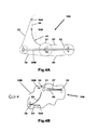
- the second guide in the form of the pulley 33 is connected to the door structure via a centre guide arm 44 shown in more detail in Fig.5 .
- the centre guide arm 44 is attached at one end to the door 20 for guiding the door 20 during opening and closing of the door by means of a roller 42.
- the second cable guide in the form of the pulley 33 is rotatably attached near a free end of the second guide arm 44 by means of a spindle 44a.
- the pulley 33 is attached to the second guide arm 44 so as to project into the centre guide channel 40 which is attached to the external surface of the side panel 12 of the motor vehicle 10.
- the second portion 27 of the second cable run is fed out into the centre guide channel 40 so that the second portion 27 of the second cable run lies within the centre guide channel 40.
- the second portion 27 moves with the pulley 33 and the door 20 so that the centre guide channel 40 is left empty when the door 20 is in the closed position. Therefore, irrespective of whether the door 20 is open or closed, the second cable run is always concealed from view by the door 20.
- a first or lower guide arm 46 The lower guide arm 46 is attached at one end by means of a bracket 45 to a bottom end of the door 20 for guiding the door 20 during opening and closing.
- the guide arm 46 includes a guide plate 49 on which is rotatably mounted a guide roller 49B (shown as a dotted outline on Fig.6 ) and the pulley 32 is rotatably attached near to a free end of the first guide arm 46.
- the guide roller 49B is engaged with the lower guide channel 48B so as to guide and support the bottom end of the door 20.
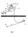
- Fig.8 there is shown in a schematic form the door actuator 30 and the drive motor 60 for the door actuator 30.
- the motor 60 drives the door actuator 30 via a clutch 61.
- the clutch 61 is overcome when a predefined torque is applied to it from the door actuator 30 thereby allowing the door 20 to be manually opened and closed if required for any reason.
- the door actuator 30 comprises first and second drive spools 31A and 31B driven by the motor 60.
- One end of the first portion 22 of the first cable 23 is attached to the first drive spool 31A and one end of the first portion 26 of the second cable 25 is attached to the second drive spool 31B.
- the first and second drive spools 31A and 31B are formed as a single combined drive spool but this need not be the case and separate synchronised spools could be used.
- the first cable 23 is wound round the first spool 31A in the opposite direction to the direction the second cable 25 is wound in.
- the first cable 23 is wound around the first spool 31A in a clockwise direction and the second cable 25 is wound around the second spool 31B in an anti-clockwise direction.
- rotation of the motor in a second or clockwise direction causes the second cable 25 to be retracted into the door actuator 30 and the first cable 23 to be reeled out from the door actuator 30 so as to close the door 20.
- door 20 will also be provided with various locks and latches but these are of a conventional construction and so are not shown or described.
- Operation of the door actuating mechanism in use is occupant controlled by means of a switch or switches.
- a switch or switches When the door 20 is required to be opened an occupant operates the appropriate switch causing the motor 60 to rotate in the door opening direction thereby retracting the first cable 23 which pulls the door 20 rearwards thereby opening it.
- an occupant When the door 20 is to be closed, an occupant operates the appropriate switch causing the motor 60 to rotate in a door closing direction thereby retracting the second cable 25 and pulling the door 20 forwardly into the closed position.
- anti-trap or anti-pinch devices will be fitted to the front end of the door 20 to prevent injury should a body part become interposed between the closing door 20 and the 'B' post 17 and that overload protection will be provided for the motor 60.
- One advantage of the invention is that it can be used with most known manual sliding door configurations to convert them to a powered form. That is to say, very few modifications have to be made to the vehicle to adapt it from a manual sliding door vehicle to a powered sliding door vehicle.
- all of the main operational components of the door actuating mechanism are mounted within the door and no modifications are required to the body structure apart from the provision of anchors for the first and second cables.
- a further advantage of the invention is that it is of a simple construction and can be manufactured in an economical manner.
- Another advantage of the invention is that it is quiet in operation and less prone to damage due to the fact that the major components are housed within the door cavity.
- first and second cables can easily be concealed from view so that they are not visible to a user of the motor vehicle.
- the door opening cable is located near a bottom end of the door it will be appreciated that it could be located near to a top end of the door provide no window is located in the upper half of the door. That is to say if the motor vehicle is a panel van or light truck the door opening cable could be located at the top or bottom of the door.
- the door closing cable is located in the centre of the door, it will be appreciated that it could be located near to a top or bottom end of the door provided an external body mounted door guide channel is located in that position and that no window is located in the upper half of the door. That is to say if the motor vehicle is a panel van or light truck the door closing cable could be located in the centre of the door, at the top of the door or at the bottom of the door.
- the disclosed arrangement for the opening and closing cables is preferred due to ease of packaging and the fact that a window may be provided in the upper half of the door.
- the motor vehicle 10 could have a sliding door fitted with a door actuating mechanism on both sides or on only one side.
Landscapes
- Engineering & Computer Science (AREA)
- Mechanical Engineering (AREA)
- Power-Operated Mechanisms For Wings (AREA)
Applications Claiming Priority (1)
| Application Number | Priority Date | Filing Date | Title |
|---|---|---|---|
| GB1111852.8A GB2492774A (en) | 2011-07-11 | 2011-07-11 | Actuation mechanism for a sliding door of a motor vehicle |
Publications (3)
| Publication Number | Publication Date |
|---|---|
| EP2546447A2 true EP2546447A2 (de) | 2013-01-16 |
| EP2546447A3 EP2546447A3 (de) | 2015-05-13 |
| EP2546447B1 EP2546447B1 (de) | 2021-07-07 |
Family
ID=44544550
Family Applications (1)
| Application Number | Title | Priority Date | Filing Date |
|---|---|---|---|
| EP12275073.0A Active EP2546447B1 (de) | 2011-07-11 | 2012-05-22 | Kraftfahrzeug mit einer Schiebetür und einem Betätigungsmechanismus für die Schiebetür |
Country Status (4)
| Country | Link |
|---|---|
| US (1) | US8690225B2 (de) |
| EP (1) | EP2546447B1 (de) |
| CN (1) | CN102877734B (de) |
| GB (1) | GB2492774A (de) |
Cited By (1)
| Publication number | Priority date | Publication date | Assignee | Title |
|---|---|---|---|---|
| FR3038930A1 (fr) * | 2015-07-15 | 2017-01-20 | Bruno Lacaux | Element d'ouverture et/ou de fermeture d'un passage |
Families Citing this family (4)
| Publication number | Priority date | Publication date | Assignee | Title |
|---|---|---|---|---|
| US9856688B2 (en) * | 2014-11-06 | 2018-01-02 | Ford Global Technologies, Llc | Bi-directional element drive system |
| MX2015006017A (es) * | 2015-04-24 | 2016-10-24 | Bode Gmbh & Co Kg Gebr | Dispositivo de accionamiento de hoja de puerta con hoja de puerta telescopica. |
| CN206722629U (zh) * | 2017-05-12 | 2017-12-08 | 广东肇庆爱龙威机电有限公司 | 用于车门自动吸合设备的执行器和车门自动吸合设备 |
| US10828970B2 (en) * | 2019-01-28 | 2020-11-10 | Toyota Motor Engineering & Manufacturing North America, Inc. | Housing assemblies for vehicle door actuation assemblies and methods of installing the same |
Citations (4)
| Publication number | Priority date | Publication date | Assignee | Title |
|---|---|---|---|---|
| US6321488B1 (en) | 1999-03-05 | 2001-11-27 | Atoma International Corp. | Power sliding vehicle door |
| WO2008025827A1 (de) | 2006-09-01 | 2008-03-06 | Ford Global Technologies, Llc | Schiebetürsystem für ein fahrzeug |
| EP2006134A1 (de) | 2007-06-21 | 2008-12-24 | Ford Global Technologies, LLC | Fahrzeugtür |
| US7856759B2 (en) | 2008-12-18 | 2010-12-28 | Ford Global Technologies, Llc | Dual action power drive unit for a vehicle door |
Family Cites Families (8)
| Publication number | Priority date | Publication date | Assignee | Title |
|---|---|---|---|---|
| JP3694494B2 (ja) * | 2002-07-02 | 2005-09-14 | 三井金属鉱業株式会社 | 車両スライド扉の動力装置 |
| KR100623152B1 (ko) | 2004-06-18 | 2006-09-19 | 현대자동차주식회사 | 승용차량의 슬라이드 도어 구조 |
| GB0601669D0 (en) | 2006-01-27 | 2006-03-08 | Delphi Tech Inc | Door operating mechanism |
| US7770961B2 (en) * | 2006-02-20 | 2010-08-10 | Magna Closures Inc. | Compact cable drive power sliding door mechanism |
| EP2076648B1 (de) * | 2006-09-26 | 2017-01-25 | Witte Automotive GmbH | Vorrichtung und verfahren zur bereitstellung eines schiebetürmechanismus |
| JP5125234B2 (ja) * | 2007-06-05 | 2013-01-23 | アイシン精機株式会社 | 車両用スライドドア装置 |
| US7575270B2 (en) * | 2007-10-26 | 2009-08-18 | Mitsuba Corporation | Opening/closing apparatus for vehicle |
| EP2221439B1 (de) * | 2009-01-16 | 2016-02-17 | Aisin Seiki Kabushiki Kaisha | Türöffnungs- und -schließvorrichtung für ein Fahrzeug |
-
2011
- 2011-07-11 GB GB1111852.8A patent/GB2492774A/en not_active Withdrawn
-
2012
- 2012-05-22 EP EP12275073.0A patent/EP2546447B1/de active Active
- 2012-07-05 US US13/541,901 patent/US8690225B2/en not_active Expired - Fee Related
- 2012-07-06 CN CN201210233961.8A patent/CN102877734B/zh not_active Expired - Fee Related
Patent Citations (4)
| Publication number | Priority date | Publication date | Assignee | Title |
|---|---|---|---|---|
| US6321488B1 (en) | 1999-03-05 | 2001-11-27 | Atoma International Corp. | Power sliding vehicle door |
| WO2008025827A1 (de) | 2006-09-01 | 2008-03-06 | Ford Global Technologies, Llc | Schiebetürsystem für ein fahrzeug |
| EP2006134A1 (de) | 2007-06-21 | 2008-12-24 | Ford Global Technologies, LLC | Fahrzeugtür |
| US7856759B2 (en) | 2008-12-18 | 2010-12-28 | Ford Global Technologies, Llc | Dual action power drive unit for a vehicle door |
Cited By (1)
| Publication number | Priority date | Publication date | Assignee | Title |
|---|---|---|---|---|
| FR3038930A1 (fr) * | 2015-07-15 | 2017-01-20 | Bruno Lacaux | Element d'ouverture et/ou de fermeture d'un passage |
Also Published As
| Publication number | Publication date |
|---|---|
| US20130014442A1 (en) | 2013-01-17 |
| EP2546447B1 (de) | 2021-07-07 |
| CN102877734B (zh) | 2016-07-06 |
| GB2492774A (en) | 2013-01-16 |
| GB201111852D0 (en) | 2011-08-24 |
| CN102877734A (zh) | 2013-01-16 |
| US8690225B2 (en) | 2014-04-08 |
| EP2546447A3 (de) | 2015-05-13 |
Similar Documents
| Publication | Publication Date | Title |
|---|---|---|
| US12264526B2 (en) | Slider window assembly with movable panel drive system | |
| EP2546447B1 (de) | Kraftfahrzeug mit einer Schiebetür und einem Betätigungsmechanismus für die Schiebetür | |
| US7021004B2 (en) | Actuating device | |
| JP5050793B2 (ja) | 車両用サンバイザ装置 | |
| JP4503978B2 (ja) | 自動車用ウィンドウシェード | |
| US7393044B2 (en) | Vehicle door opening and closing structure | |
| CN101445082B (zh) | 门边缘保护装置 | |
| US7144068B2 (en) | Drive mechanism for selectively opening and closing a closure panel manually or automatically | |
| JP2001336352A (ja) | 車両用スライドドア装置 | |
| EP3757339B1 (de) | Objektbewegungsvorrichtung | |
| EP2532545B1 (de) | Blendenvorrichtung für fahrzeugfenster | |
| CN109641510B (zh) | 用于机动车的玻璃的遮荫装置 | |
| CN108081932B (zh) | 用于天窗的多功能驱动系统 | |
| CN107980027B (zh) | 用于机动车的窗玻璃的遮蔽装置 | |
| CA2480816C (en) | Powered sliding device of vehicle sliding door | |
| GB2074228A (en) | Door operating mechanism | |
| JP4658694B2 (ja) | 車両用ドア開閉構造 | |
| JP4670617B2 (ja) | 車体後部構造 | |
| JP7586390B2 (ja) | 車両用スライドドア開閉装置 | |
| JP4900034B2 (ja) | チルトアンドシェードパネル装置 | |
| JP5207397B2 (ja) | カーテン開閉装置 | |
| JP5001188B2 (ja) | スライドドア | |
| JP5706222B2 (ja) | 車両用開閉体の駆動装置 | |
| TWM536171U (zh) | 汽車天窗致動機構 | |
| JP2007217865A (ja) | 車両用自動開閉装置 |
Legal Events
| Date | Code | Title | Description |
|---|---|---|---|
| PUAI | Public reference made under article 153(3) epc to a published international application that has entered the european phase |
Free format text: ORIGINAL CODE: 0009012 |
|
| AK | Designated contracting states |
Kind code of ref document: A2 Designated state(s): AL AT BE BG CH CY CZ DE DK EE ES FI FR GB GR HR HU IE IS IT LI LT LU LV MC MK MT NL NO PL PT RO RS SE SI SK SM TR |
|
| AX | Request for extension of the european patent |
Extension state: BA ME |
|
| PUAL | Search report despatched |
Free format text: ORIGINAL CODE: 0009013 |
|
| AK | Designated contracting states |
Kind code of ref document: A3 Designated state(s): AL AT BE BG CH CY CZ DE DK EE ES FI FR GB GR HR HU IE IS IT LI LT LU LV MC MK MT NL NO PL PT RO RS SE SI SK SM TR |
|
| AX | Request for extension of the european patent |
Extension state: BA ME |
|
| RIC1 | Information provided on ipc code assigned before grant |
Ipc: E05F 15/14 00000000AFI20150407BHEP |
|
| 17P | Request for examination filed |
Effective date: 20151113 |
|
| RBV | Designated contracting states (corrected) |
Designated state(s): AL AT BE BG CH CY CZ DE DK EE ES FI FR GB GR HR HU IE IS IT LI LT LU LV MC MK MT NL NO PL PT RO RS SE SI SK SM TR |
|
| STAA | Information on the status of an ep patent application or granted ep patent |
Free format text: STATUS: EXAMINATION IS IN PROGRESS |
|
| 17Q | First examination report despatched |
Effective date: 20180709 |
|
| REG | Reference to a national code |
Ref country code: DE Ref legal event code: R079 Ref document number: 602012076030 Country of ref document: DE Free format text: PREVIOUS MAIN CLASS: E05F0015140000 Ipc: E05F0015643000 |
|
| GRAP | Despatch of communication of intention to grant a patent |
Free format text: ORIGINAL CODE: EPIDOSNIGR1 |
|
| RIC1 | Information provided on ipc code assigned before grant |
Ipc: E05F 15/646 20150101ALI20210121BHEP Ipc: E05F 15/643 20150101AFI20210121BHEP |
|
| STAA | Information on the status of an ep patent application or granted ep patent |
Free format text: STATUS: GRANT OF PATENT IS INTENDED |
|
| INTG | Intention to grant announced |
Effective date: 20210225 |
|
| GRAS | Grant fee paid |
Free format text: ORIGINAL CODE: EPIDOSNIGR3 |
|
| GRAA | (expected) grant |
Free format text: ORIGINAL CODE: 0009210 |
|
| STAA | Information on the status of an ep patent application or granted ep patent |
Free format text: STATUS: THE PATENT HAS BEEN GRANTED |
|
| AK | Designated contracting states |
Kind code of ref document: B1 Designated state(s): AL AT BE BG CH CY CZ DE DK EE ES FI FR GB GR HR HU IE IS IT LI LT LU LV MC MK MT NL NO PL PT RO RS SE SI SK SM TR |
|
| REG | Reference to a national code |
Ref country code: GB Ref legal event code: FG4D |
|
| REG | Reference to a national code |
Ref country code: AT Ref legal event code: REF Ref document number: 1408757 Country of ref document: AT Kind code of ref document: T Effective date: 20210715 |
|
| REG | Reference to a national code |
Ref country code: DE Ref legal event code: R096 Ref document number: 602012076030 Country of ref document: DE |
|
| REG | Reference to a national code |
Ref country code: IE Ref legal event code: FG4D |
|
| REG | Reference to a national code |
Ref country code: LT Ref legal event code: MG9D |
|
| REG | Reference to a national code |
Ref country code: NL Ref legal event code: MP Effective date: 20210707 |
|
| REG | Reference to a national code |
Ref country code: AT Ref legal event code: MK05 Ref document number: 1408757 Country of ref document: AT Kind code of ref document: T Effective date: 20210707 |
|
| PG25 | Lapsed in a contracting state [announced via postgrant information from national office to epo] |
Ref country code: FI Free format text: LAPSE BECAUSE OF FAILURE TO SUBMIT A TRANSLATION OF THE DESCRIPTION OR TO PAY THE FEE WITHIN THE PRESCRIBED TIME-LIMIT Effective date: 20210707 Ref country code: ES Free format text: LAPSE BECAUSE OF FAILURE TO SUBMIT A TRANSLATION OF THE DESCRIPTION OR TO PAY THE FEE WITHIN THE PRESCRIBED TIME-LIMIT Effective date: 20210707 Ref country code: NL Free format text: LAPSE BECAUSE OF FAILURE TO SUBMIT A TRANSLATION OF THE DESCRIPTION OR TO PAY THE FEE WITHIN THE PRESCRIBED TIME-LIMIT Effective date: 20210707 Ref country code: RS Free format text: LAPSE BECAUSE OF FAILURE TO SUBMIT A TRANSLATION OF THE DESCRIPTION OR TO PAY THE FEE WITHIN THE PRESCRIBED TIME-LIMIT Effective date: 20210707 Ref country code: NO Free format text: LAPSE BECAUSE OF FAILURE TO SUBMIT A TRANSLATION OF THE DESCRIPTION OR TO PAY THE FEE WITHIN THE PRESCRIBED TIME-LIMIT Effective date: 20211007 Ref country code: PT Free format text: LAPSE BECAUSE OF FAILURE TO SUBMIT A TRANSLATION OF THE DESCRIPTION OR TO PAY THE FEE WITHIN THE PRESCRIBED TIME-LIMIT Effective date: 20211108 Ref country code: LT Free format text: LAPSE BECAUSE OF FAILURE TO SUBMIT A TRANSLATION OF THE DESCRIPTION OR TO PAY THE FEE WITHIN THE PRESCRIBED TIME-LIMIT Effective date: 20210707 Ref country code: BG Free format text: LAPSE BECAUSE OF FAILURE TO SUBMIT A TRANSLATION OF THE DESCRIPTION OR TO PAY THE FEE WITHIN THE PRESCRIBED TIME-LIMIT Effective date: 20211007 Ref country code: AT Free format text: LAPSE BECAUSE OF FAILURE TO SUBMIT A TRANSLATION OF THE DESCRIPTION OR TO PAY THE FEE WITHIN THE PRESCRIBED TIME-LIMIT Effective date: 20210707 Ref country code: HR Free format text: LAPSE BECAUSE OF FAILURE TO SUBMIT A TRANSLATION OF THE DESCRIPTION OR TO PAY THE FEE WITHIN THE PRESCRIBED TIME-LIMIT Effective date: 20210707 Ref country code: SE Free format text: LAPSE BECAUSE OF FAILURE TO SUBMIT A TRANSLATION OF THE DESCRIPTION OR TO PAY THE FEE WITHIN THE PRESCRIBED TIME-LIMIT Effective date: 20210707 |
|
| PG25 | Lapsed in a contracting state [announced via postgrant information from national office to epo] |
Ref country code: PL Free format text: LAPSE BECAUSE OF FAILURE TO SUBMIT A TRANSLATION OF THE DESCRIPTION OR TO PAY THE FEE WITHIN THE PRESCRIBED TIME-LIMIT Effective date: 20210707 Ref country code: LV Free format text: LAPSE BECAUSE OF FAILURE TO SUBMIT A TRANSLATION OF THE DESCRIPTION OR TO PAY THE FEE WITHIN THE PRESCRIBED TIME-LIMIT Effective date: 20210707 Ref country code: GR Free format text: LAPSE BECAUSE OF FAILURE TO SUBMIT A TRANSLATION OF THE DESCRIPTION OR TO PAY THE FEE WITHIN THE PRESCRIBED TIME-LIMIT Effective date: 20211008 |
|
| REG | Reference to a national code |
Ref country code: DE Ref legal event code: R097 Ref document number: 602012076030 Country of ref document: DE |
|
| PG25 | Lapsed in a contracting state [announced via postgrant information from national office to epo] |
Ref country code: DK Free format text: LAPSE BECAUSE OF FAILURE TO SUBMIT A TRANSLATION OF THE DESCRIPTION OR TO PAY THE FEE WITHIN THE PRESCRIBED TIME-LIMIT Effective date: 20210707 |
|
| PLBE | No opposition filed within time limit |
Free format text: ORIGINAL CODE: 0009261 |
|
| STAA | Information on the status of an ep patent application or granted ep patent |
Free format text: STATUS: NO OPPOSITION FILED WITHIN TIME LIMIT |
|
| PG25 | Lapsed in a contracting state [announced via postgrant information from national office to epo] |
Ref country code: SM Free format text: LAPSE BECAUSE OF FAILURE TO SUBMIT A TRANSLATION OF THE DESCRIPTION OR TO PAY THE FEE WITHIN THE PRESCRIBED TIME-LIMIT Effective date: 20210707 Ref country code: SK Free format text: LAPSE BECAUSE OF FAILURE TO SUBMIT A TRANSLATION OF THE DESCRIPTION OR TO PAY THE FEE WITHIN THE PRESCRIBED TIME-LIMIT Effective date: 20210707 Ref country code: RO Free format text: LAPSE BECAUSE OF FAILURE TO SUBMIT A TRANSLATION OF THE DESCRIPTION OR TO PAY THE FEE WITHIN THE PRESCRIBED TIME-LIMIT Effective date: 20210707 Ref country code: EE Free format text: LAPSE BECAUSE OF FAILURE TO SUBMIT A TRANSLATION OF THE DESCRIPTION OR TO PAY THE FEE WITHIN THE PRESCRIBED TIME-LIMIT Effective date: 20210707 Ref country code: CZ Free format text: LAPSE BECAUSE OF FAILURE TO SUBMIT A TRANSLATION OF THE DESCRIPTION OR TO PAY THE FEE WITHIN THE PRESCRIBED TIME-LIMIT Effective date: 20210707 Ref country code: AL Free format text: LAPSE BECAUSE OF FAILURE TO SUBMIT A TRANSLATION OF THE DESCRIPTION OR TO PAY THE FEE WITHIN THE PRESCRIBED TIME-LIMIT Effective date: 20210707 |
|
| 26N | No opposition filed |
Effective date: 20220408 |
|
| PG25 | Lapsed in a contracting state [announced via postgrant information from national office to epo] |
Ref country code: IT Free format text: LAPSE BECAUSE OF FAILURE TO SUBMIT A TRANSLATION OF THE DESCRIPTION OR TO PAY THE FEE WITHIN THE PRESCRIBED TIME-LIMIT Effective date: 20210707 |
|
| PGFP | Annual fee paid to national office [announced via postgrant information from national office to epo] |
Ref country code: DE Payment date: 20220411 Year of fee payment: 11 |
|
| REG | Reference to a national code |
Ref country code: CH Ref legal event code: PL |
|
| REG | Reference to a national code |
Ref country code: BE Ref legal event code: MM Effective date: 20220531 |
|
| GBPC | Gb: european patent ceased through non-payment of renewal fee |
Effective date: 20220522 |
|
| PG25 | Lapsed in a contracting state [announced via postgrant information from national office to epo] |
Ref country code: MC Free format text: LAPSE BECAUSE OF FAILURE TO SUBMIT A TRANSLATION OF THE DESCRIPTION OR TO PAY THE FEE WITHIN THE PRESCRIBED TIME-LIMIT Effective date: 20210707 Ref country code: LU Free format text: LAPSE BECAUSE OF NON-PAYMENT OF DUE FEES Effective date: 20220522 Ref country code: LI Free format text: LAPSE BECAUSE OF NON-PAYMENT OF DUE FEES Effective date: 20220531 Ref country code: CH Free format text: LAPSE BECAUSE OF NON-PAYMENT OF DUE FEES Effective date: 20220531 |
|
| PG25 | Lapsed in a contracting state [announced via postgrant information from national office to epo] |
Ref country code: IE Free format text: LAPSE BECAUSE OF NON-PAYMENT OF DUE FEES Effective date: 20220522 Ref country code: FR Free format text: LAPSE BECAUSE OF NON-PAYMENT OF DUE FEES Effective date: 20220531 |
|
| PG25 | Lapsed in a contracting state [announced via postgrant information from national office to epo] |
Ref country code: GB Free format text: LAPSE BECAUSE OF NON-PAYMENT OF DUE FEES Effective date: 20220522 Ref country code: BE Free format text: LAPSE BECAUSE OF NON-PAYMENT OF DUE FEES Effective date: 20220531 |
|
| REG | Reference to a national code |
Ref country code: DE Ref legal event code: R119 Ref document number: 602012076030 Country of ref document: DE |
|
| PG25 | Lapsed in a contracting state [announced via postgrant information from national office to epo] |
Ref country code: HU Free format text: LAPSE BECAUSE OF FAILURE TO SUBMIT A TRANSLATION OF THE DESCRIPTION OR TO PAY THE FEE WITHIN THE PRESCRIBED TIME-LIMIT; INVALID AB INITIO Effective date: 20120522 |
|
| PG25 | Lapsed in a contracting state [announced via postgrant information from national office to epo] |
Ref country code: MK Free format text: LAPSE BECAUSE OF FAILURE TO SUBMIT A TRANSLATION OF THE DESCRIPTION OR TO PAY THE FEE WITHIN THE PRESCRIBED TIME-LIMIT Effective date: 20210707 Ref country code: DE Free format text: LAPSE BECAUSE OF NON-PAYMENT OF DUE FEES Effective date: 20231201 Ref country code: CY Free format text: LAPSE BECAUSE OF FAILURE TO SUBMIT A TRANSLATION OF THE DESCRIPTION OR TO PAY THE FEE WITHIN THE PRESCRIBED TIME-LIMIT Effective date: 20210707 |
|
| PG25 | Lapsed in a contracting state [announced via postgrant information from national office to epo] |
Ref country code: TR Free format text: LAPSE BECAUSE OF FAILURE TO SUBMIT A TRANSLATION OF THE DESCRIPTION OR TO PAY THE FEE WITHIN THE PRESCRIBED TIME-LIMIT Effective date: 20210707 |
|
| PG25 | Lapsed in a contracting state [announced via postgrant information from national office to epo] |
Ref country code: MT Free format text: LAPSE BECAUSE OF FAILURE TO SUBMIT A TRANSLATION OF THE DESCRIPTION OR TO PAY THE FEE WITHIN THE PRESCRIBED TIME-LIMIT Effective date: 20210707 |