EP2546448A2 - Dispositif de décalage dýun objet de décalage - Google Patents
Dispositif de décalage dýun objet de décalage Download PDFInfo
- Publication number
- EP2546448A2 EP2546448A2 EP12176290A EP12176290A EP2546448A2 EP 2546448 A2 EP2546448 A2 EP 2546448A2 EP 12176290 A EP12176290 A EP 12176290A EP 12176290 A EP12176290 A EP 12176290A EP 2546448 A2 EP2546448 A2 EP 2546448A2
- Authority
- EP
- European Patent Office
- Prior art keywords
- sliding
- underside
- sliding element
- rail
- fastening element
- Prior art date
- Legal status (The legal status is an assumption and is not a legal conclusion. Google has not performed a legal analysis and makes no representation as to the accuracy of the status listed.)
- Granted
Links
- 239000011521 glass Substances 0.000 claims description 50
- 238000006073 displacement reaction Methods 0.000 claims description 9
- 239000000853 adhesive Substances 0.000 description 13
- 230000001070 adhesive effect Effects 0.000 description 13
- 125000006850 spacer group Chemical group 0.000 description 12
- 238000005096 rolling process Methods 0.000 description 11
- 238000010276 construction Methods 0.000 description 6
- 238000009434 installation Methods 0.000 description 5
- 239000000463 material Substances 0.000 description 4
- 239000012790 adhesive layer Substances 0.000 description 3
- 229910052782 aluminium Inorganic materials 0.000 description 3
- XAGFODPZIPBFFR-UHFFFAOYSA-N aluminium Chemical compound [Al] XAGFODPZIPBFFR-UHFFFAOYSA-N 0.000 description 3
- 239000011152 fibreglass Substances 0.000 description 3
- 241000951498 Brachypteraciidae Species 0.000 description 2
- 230000009286 beneficial effect Effects 0.000 description 2
- 238000009413 insulation Methods 0.000 description 2
- 229910052751 metal Inorganic materials 0.000 description 2
- 239000002184 metal Substances 0.000 description 2
- 239000004033 plastic Substances 0.000 description 2
- 229920003023 plastic Polymers 0.000 description 2
- 229920001296 polysiloxane Polymers 0.000 description 2
- 238000007789 sealing Methods 0.000 description 2
- 230000007704 transition Effects 0.000 description 2
- 241000446313 Lamella Species 0.000 description 1
- 238000011010 flushing procedure Methods 0.000 description 1
- 230000003993 interaction Effects 0.000 description 1
- 239000010410 layer Substances 0.000 description 1
- 239000000203 mixture Substances 0.000 description 1
- 238000005192 partition Methods 0.000 description 1
- 230000000630 rising effect Effects 0.000 description 1
- XLYOFNOQVPJJNP-UHFFFAOYSA-N water Substances O XLYOFNOQVPJJNP-UHFFFAOYSA-N 0.000 description 1
- 239000002023 wood Substances 0.000 description 1
Images


Classifications
-
- E—FIXED CONSTRUCTIONS
- E06—DOORS, WINDOWS, SHUTTERS, OR ROLLER BLINDS IN GENERAL; LADDERS
- E06B—FIXED OR MOVABLE CLOSURES FOR OPENINGS IN BUILDINGS, VEHICLES, FENCES OR LIKE ENCLOSURES IN GENERAL, e.g. DOORS, WINDOWS, BLINDS, GATES
- E06B3/00—Window sashes, door leaves, or like elements for closing wall or like openings; Layout of fixed or moving closures, e.g. windows in wall or like openings; Features of rigidly-mounted outer frames relating to the mounting of wing frames
- E06B3/02—Wings made completely of glass
-
- E—FIXED CONSTRUCTIONS
- E05—LOCKS; KEYS; WINDOW OR DOOR FITTINGS; SAFES
- E05D—HINGES OR SUSPENSION DEVICES FOR DOORS, WINDOWS OR WINGS
- E05D15/00—Suspension arrangements for wings
- E05D15/06—Suspension arrangements for wings for wings sliding horizontally more or less in their own plane
- E05D15/0621—Details, e.g. suspension or supporting guides
- E05D15/066—Details, e.g. suspension or supporting guides for wings supported at the bottom
- E05D15/0665—Details, e.g. suspension or supporting guides for wings supported at the bottom on wheels with fixed axis
-
- E—FIXED CONSTRUCTIONS
- E05—LOCKS; KEYS; WINDOW OR DOOR FITTINGS; SAFES
- E05D—HINGES OR SUSPENSION DEVICES FOR DOORS, WINDOWS OR WINGS
- E05D15/00—Suspension arrangements for wings
- E05D15/06—Suspension arrangements for wings for wings sliding horizontally more or less in their own plane
- E05D15/08—Suspension arrangements for wings for wings sliding horizontally more or less in their own plane consisting of two or more independent parts movable each in its own guides
-
- E—FIXED CONSTRUCTIONS
- E05—LOCKS; KEYS; WINDOW OR DOOR FITTINGS; SAFES
- E05Y—INDEXING SCHEME ASSOCIATED WITH SUBCLASSES E05D AND E05F, RELATING TO CONSTRUCTION ELEMENTS, ELECTRIC CONTROL, POWER SUPPLY, POWER SIGNAL OR TRANSMISSION, USER INTERFACES, MOUNTING OR COUPLING, DETAILS, ACCESSORIES, AUXILIARY OPERATIONS NOT OTHERWISE PROVIDED FOR, APPLICATION THEREOF
- E05Y2800/00—Details, accessories and auxiliary operations not otherwise provided for
- E05Y2800/67—Materials; Strength alteration thereof
- E05Y2800/672—Glass
-
- E—FIXED CONSTRUCTIONS
- E05—LOCKS; KEYS; WINDOW OR DOOR FITTINGS; SAFES
- E05Y—INDEXING SCHEME ASSOCIATED WITH SUBCLASSES E05D AND E05F, RELATING TO CONSTRUCTION ELEMENTS, ELECTRIC CONTROL, POWER SUPPLY, POWER SIGNAL OR TRANSMISSION, USER INTERFACES, MOUNTING OR COUPLING, DETAILS, ACCESSORIES, AUXILIARY OPERATIONS NOT OTHERWISE PROVIDED FOR, APPLICATION THEREOF
- E05Y2900/00—Application of doors, windows, wings or fittings thereof
- E05Y2900/10—Application of doors, windows, wings or fittings thereof for buildings or parts thereof
- E05Y2900/13—Type of wing
- E05Y2900/132—Doors
Definitions
- the invention relates to a device for horizontal linear displacement of one or more sliding elements, e.g. sliding elements in the form of a glass element or a wall element, wherein the sliding element is linearly displaceably mounted in an upper region and in a lower region in the horizontal direction, and wherein the displaceable mounting in the lower region of a sliding element by means of an external roller device, wherein the roller device more along the direction of displacement of the sliding element arranged rollers, on which the sliding element is mounted by means of at least one rail, which at least one rail is attached to the underside of the sliding element, wherein the sliding element on its side facing the roller device at least one fastening element for securing the at least one rail has at the bottom of the sliding element
- the frames of the glass elements used should be as delicate as possible, so as not to interfere with the light and to emphasize the ease of construction.
- the rail construction should visually appear as little as possible, flush with the floor and easy to walk on. In addition to these formal requirements, today there are also high demands on the tightness and thermal insulation values of such sliding systems.
- the rollers are mounted on the underside of the sliding element and run on rails on the ground.
- These rails can be designed as U-profiles, which are installed sunk in the ground.
- the sliding element engages in the U-profile, whereby the roll apparatus and the frame are partially covered and a floor-flush construction is possible. For glass sliding walls, this is currently the most common solution.
- a rolling system in which the sliding element has no roll apparatus. Instead, rollers are arranged in the bottom-side holding profile instead of the running rail at regular intervals.
- the glass element which is provided only with a circumferential frame of folded sheet metal.
- the guide of the glass element in the transverse direction is effected by two strip brushes, which sit in recesses in the vertical flanges of the holding profile.
- the frame is so slim that it disappears completely in the holding profile.
- wide grooves are created in the ground, with all the above-mentioned disadvantages.
- a rail system is preferably described for shower partitions in which the rail apparatus consists of individual slats, which are held together by transverse bolts. These cross pins serve as axes for rotatable sleeves, on where the sliding elements run.
- the guide in the transverse direction is similar to WO 94/17275 by an intervention of the sliding element in the slat gap.
- the underside of the sliding element has a different shape from a continuous plane, and wherein the at least one fastening element is at least partially positively connected to the underside of the sliding element, and wherein the at least one fastening element the two side surfaces of the sliding element flush adjoins or the fastener laterally does not protrude over the side surfaces in terms of its transverse extent.
- the fastener is not on the sliding elements over its side surfaces and is connected only at the bottom with the sliding element, so does not affect the side surfaces over. Thereby, the sliding element can be kept slim and the fastener does not widen the sliding element.
- the frame can be optically very narrow or completely invisible at the bottom.
- the side surfaces are those surfaces which are vertical and lie in the direction of displacement; in contrast to the end faces, which are normal to the direction of displacement.
- the side surfaces are e.g. Glass panes in a glass sliding element.
- the fastener is - after installation - part of the edge bond of the sliding element and is preferably flush mounted in the edge seal.
- the object is achieved with a device mentioned in the introduction, in which according to the invention the roller device has longitudinally extending lamellae, between which lamellae the rollers of the roller device are arranged, wherein the at least one rail projects at least partially into the lamella intermediate space.
- the at least one rail can be made narrower than the fastening element and thus also narrower than the sliding element per se. By doing that the rail and not the entire sliding element projects into the space between the slats, the lower outer edges of the sliding element can be arranged above the upper edge of the lamellar grid.
- the underside of the sliding element has a deviating from a continuous plane shape, and the at least one fastening element with the underside of the sliding element is at least partially positively connected, and wherein the at least one Fastening element flush adjoins the two side surfaces of the sliding element or the fastening element laterally does not protrude beyond the side surfaces in terms of its transverse extent.
- fastening element contacts the underside at least in the edge region or the edge regions of the underside of the sliding element.
- edge area refers to the area in which the underside merges into the side surfaces (and not the transition area bottom side - end faces).
- the sliding element is held together stably and in particular, the fastening element can also serve as fall protection for the side surfaces of the sliding element.
- the fastener may directly contact the underside of the contact area (and, e.g., mechanical connection such as by screws or bolts) or the fastener may be adhesively bonded to the underside in the contact area;
- the term "contact” thus also includes that between the bottom and fastener, an adhesive may be provided.
- the fastening element contacts the underside of the sliding element along its entire longitudinal extent, at least in the edge area (s).
- fastening element contacts the underside of the sliding element along its entire transverse extent.
- longitudinal extension means "in the direction of displacement” of the sliding element, while “transverse” or “transverse extent” means normal to the longitudinal extent.
- At least one depression in the form of a groove extending in the longitudinal direction of the sliding element is provided on the underside, into which at least one groove protrudes the fastening element at least with a fastening element section.
- the sliding element is supported on the fastening element via the groove.
- the fastening element contacts the underside of the sliding element in the edge regions; but it can also be provided that the fastening element additionally contacted in the groove, the underside of the sliding element over the entire surface, so that there is a full-surface connection with the entire bottom.
- the actual connection can be made by means of screws, bolts etc or preferably by means of adhesive, and a combination of these connection possibilities is conceivable.
- a good connection between the fastening element and the sliding element also results if the underside has in its edge regions, towards the side surfaces at least one chamfer running in the longitudinal extension or at least one fold, wherein the fastening element at least in the region of the chamfers the underside of the sliding element or seams contacted over the entire surface or connected to this area.
- the fastening element is adhesively bonded to the underside at least in certain regions, specifically at least at the contact surfaces in the edge region.
- a full-surface bonding of the fastening element may be provided with the underside of the sliding element.
- the fastening element is integrated in the edge connection of the sliding element and also establishes a connection to the rail on which the sliding element can be moved on the rolling device.
- the at least one rail is attached to a fastener, that is, that the rail and fastener are formed as separate components and are assembled during assembly of the device, or it is with Advantage provided that fastener and rail are integrally formed.
- the one-piece design of fastener and rail (the rail is integrally integrated into the fastener) has advantages in terms of stability and installation costs, a two-part design (rail and fastener formed as separate components), for example, in retrofits beneficial.
- Another advantage of Zwei Westernmaschine is that the thermal insulation properties in the region of the fastener can be significantly improved by a suitable choice of the material for the fastener.
- the adhesive joint between the fastener and the side surfaces in the form of glass elements can be made very narrow, since GRP and glass have a very similar or almost identical thermal expansion coefficient.
- the at least one rail has a smaller width / transverse extent than the fastening element or the width of the underside of the sliding element.
- the rail is mounted centrally in relation to the fastening element on this or connected thereto.
- roller device is arranged below a floor top edge or extends to a maximum level with the floor top edge.
- the upper edges of the rollers of the roller device are below the floor level.
- the roller device has lamellae extending in the longitudinal direction, between which lamellae the rollers of the roller device are arranged.
- the roller device thus has a lamellar grid, formed by a bandage of lamellae running parallel to the sliding direction.
- rollers are not over the top of the lamellar Association before.
- the slats are connected to each other by means of running under the slats cross members.
- the slats can be easily attached to a substructure.
- the cross members act as spacers to the substructure, whereby a problem-free drainage can take place.
- the rollers have tapered running surfaces on which rests the at least one rail with its rail profile, wherein preferably the rollers have two beveled, tapered running surfaces.
- the invention can be used for any sliding walls, but the invention is particularly well suited for glass sliding elements, such as insulating glass elements, as doors, windows, sliding walls u. Like. Can be used.
- one or more, preferably all sliding elements are designed as glass sliding elements, with at least two or more, in particular three glass panes, is / are.
- glass sliding elements with almost any size glass panes in triple glazing can be performed flush with the floor, the glass sliding elements without external and internal frame and without wide grooves in the bottom area.
- the two side surfaces are formed by glass sheets, wherein the at least one fastening element, the two side surfaces contacted on its underside or is connected thereto.
- the at least one intermediate disk protrudes less far down than the two outer disks, and wherein the fastening element protrudes with at least one portion into the free space created between the two outer disks.
- FIG. 1 shows a vertical section through an inventive device 100 with a plurality of sliding elements 1, wherein in the section shown three sliding elements 1 can be seen.
- the sliding elements 1 are glass sliding elements.
- the sliding elements 1 are linearly displaceable in an upper region and in a lower region in the horizontal direction (i.e., in the direction normal to the plane of the page), i. the sliding elements are displaceable along their longitudinal extent.
- the displaceable storage takes place in the lower region of the sliding elements 1 by means of an external roller device 10, while the storage in the upper region, for example, takes place with a sliding bearing device 50.
- FIG. 2 shows the device 100 with the sliding elements 1, which are slidably mounted on the roller device 10, in a schematic plan view.
- the roller device 10 has several along the direction of displacement of the sliding element 1 arranged rollers 11, as shown in FIG. 2 can be seen.
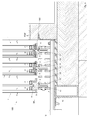
- FIG. 3 now shows the device 100 in a vertical section through the device, in a lower region of the sliding elements 1 and in the region of the roller device 10th
- the roller device 10 is arranged below a floor upper edge FOK. By buried in the ground roller device a good accessibility is guaranteed. For good accessibility is also provided that the roller device 10 has longitudinally extending lamellae 12, between which slats 12, the rollers 11 of the roller device 10 are arranged. The roller device thus has a lamellar grid, formed by a bandage of lamellae running parallel to the sliding direction.
- Each of the three sliding elements 1 is slidably mounted by means of a separate rail 4 on a plurality of rollers 4 arranged one behind the other.
- the upper edges 11 "(see, eg Figure 4,4a ) of the rollers 11 of the roller device 10 are below the upper floor edge FOK, where it is as shown of particular advantage, if the rollers are not on the upper edge of the laminate laminate OKL (see FIG. 3 ) stand out.
- Adjacent rollers 11 are rotatably mounted on a common, rigid shaft / axis 14, preferably ball-bearing mounted.
- the shaft 14 itself is rigidly attached to the slats.
- the slats can be easily attached to a substructure.
- the cross members act as spacers to the substructure, whereby a problem-free drainage can take place.
- the three sliding elements 1 are designed as glass sliding elements and each consist of two outer side surfaces or glass panes 1a, 1b and a middle glass pane 1c.
- the intermediate disc 1c protrudes less far down than the two outer discs 1a, 1b.
- the discs 1a, 1b, 1c are held in a known manner by means of spacer elements 70 at a distance from each other.
- All three sliding element 1 shown are mounted by means of a rail 4 on the associated rollers 11, wherein the rail 4 is mounted respectively on the underside 2 of the sliding element 1; also be on the FIG. 4 refer, which shows the left sliding element 1 with removed fastener 3.
- Each sliding element 1 now has, on its underside 2 facing the roller device 10, a fastening element 3 for fastening the at least one rail 4 to the underside 2 of the sliding element 1.
- the fastening element 3 of the left sliding element (see also FIG. 4 ) is integrally formed with the rail 4, while in the middle and right sliding element, the fastening element and the rail are formed separately.
- the underside 2 of a sliding element 1 has a deviating from a continuous plane shape, namely the bottom 2 of a glass sliding element 1 from the two bottom sides 2 'of the glass sheets 1a, 1b and (in those areas where a spacer element 70) is provided from the outer side or faces 2 "of the spacer element 70, as well as from the underside of the slide 1c, as well as a part of the inner surfaces of the discs 1a, 1b and the side surfaces of the disc 1c protruding into the region 21.
- the fastener 3 is connected to the bottom 2 of the sliding element 1 at least partially positively and closes at the two side surfaces 1a, 1b of the sliding element 1 flush.
- Flushing means that the outer surface of the side surfaces 1a, 1b and the outer sides of the fastening element 3 lie in a common plane.
- the fastener is not in the sliding element 1 on the side surfaces 1a, 1b and is connected only at the bottom with the sliding element, so does not affect the side surfaces over. Thereby, the sliding element can be kept slim and the fastener does not widen the sliding element.
- the frame can be optically very narrow in the lower area.
- the fastener is - after installation - part of the edge bond of the sliding element and is preferably flush mounted in the edge seal.
- the fastening element 3 makes contact with the underside 2 at least in the edge regions 2 ', ie in the example shown on the undersides 2' of the glass panes 1a, 1b of the sliding element 1.
- the adhesive 90 is also clearly visible in the region between the disks 1a, 1b, so that the outer disks 1a, 1b are in each case tightly connected to the middle disk 1c.
- the glass sliding element is held together stably and in particular, the fastening element can also serve as fall protection for the glass surfaces 1a, 1b of the sliding glass element.
- the fastener may directly contact the underside of the contact area (and, e.g., mechanical connection such as by screws or bolts) or the fastener may be adhesively bonded to the underside in the contact area;
- the term "contact” thus also includes that between the bottom and fastener, an adhesive may be provided.
- FIG. 3 is shown in all variants, that the fastening element 3 is bonded to the underside 2, the adhesive layer between the fastening element 3 and the sliding element 1 is designated by the reference numeral 90.
- a (horizontal) gap which is filled with adhesive 90, so that a continuous, flush outer surface (outer surface of the discs 1a, 1b, adhesive 90th , Outer surface of the fastening element 3).
- the fastening element forms an edge bond with the outer glass panes or the outer glass panes are connected to one another by means of the fastening element in an edge bond.
- the fastening element can thus be considered in the assembled state as part of the sliding element.
- the sliding element 1 is mounted vertically on the fastening element 3 and thus standing on the rail 4.
- the fastening element 3 preferably contacts the underside 2 of the sliding element 1 along its entire longitudinal extent.
- the underside of the sliding element in the event that the spacer elements extend 70 (70 ') over the entire longitudinal extent of the sliding element, a quasi-continuous underside.
- spacer elements are provided only selectively, in the areas between the spacers thus there is no continuous bottom, but the sliding elements is initially "open” and is only by introducing the adhesive 90, which also acts as a seal, and the fastener completed.
- the adhesive is as far as necessary, usually introduced approximately up to the level of the underside of the spacer elements.
- the at least one intermediate disk 1c protrudes less far downwards than the two outer disks 1a, 1b.
- the resulting free space between the two outer disks 1a, 1b forms a groove 21 extending along the longitudinal extent on the underside 2 of the sliding element 1, and the fastening element 3 can project into this groove 21 with a section 3a.
- the sliding element 1 is supported on the fastening element 3 via the groove 21.
- the fastening element 3 contacts the underside of the sliding element 1 in the edge regions; but it can also be provided that the fastening element additionally contacted in the groove, the underside of the sliding element over the entire surface, so that there is a full-surface connection with the entire bottom.
- the actual connection can be done by means of screws, bolts etc or preferably by means of (elastic) adhesive, a combination of these connection possibilities is conceivable.
- the lower edge of the sliding elements is in the illustrated embodiment ( FIG. 3, 4 ) formed as a U-shaped stepped fold, in which a hat-shaped fastening element, preferably made of anodized aluminum, is glued. Between the glass edge of the middle pane 1c and the fastening element 3 punctiform intermediate layers of plastic (not shown) can be introduced, via which the load transfer of the glass element takes place.
- the hat flanges of the profile can be made very delicate. They form the mechanical fall protection for the two outer panes and can simultaneously serve as a carrier of a sealing profile on the inside or as edge protection for the glass element on the outside.
- the fastener 3 made of a metal, preferably made of anodized aluminum.
- the fastener 3 and the rail 4 are made in one piece.
- the fastening element 3 can also be formed, for example, from GFRP (glass fiber reinforced plastic), as shown in the middle.
- the fastener 3 has a groove into which the - preferably metallic - rail 4 is inserted.
- the rail 4 is secured in the groove in the longitudinal direction against displacement.
- the fastening element 3 is formed from two GRP plates (for example extruded GRP), the rail 4 is screwed by means of a fastening element, for example a screw 105, through the FRP plate.
- a fastening element for example a screw 105
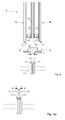
- FIGS. 5 and 6 show yet another variant of the invention, here the example of a double glazing, this variant is just as well suited for 3- or multiple glazing.
- the two outer discs 1a, 1b are held by means of spacers 70 'at a distance from each other.
- the sliding element 1 has on its underside 2 in the edge regions, to the side surfaces 1 a, 1 b in each case at least one extending in the longitudinal direction chamfer 22, wherein the fastener 3, the underside 2 of the sliding element 1 at least in the region of the chamfered area 22 contacted over the entire surface or connected to this area.
- the connection is made by means of a preferably elastic adhesive layer 90 analogous to the embodiments FIG. 3 and Figures 4 and 4a , As well as in the Figure 3 - 4a shown Embodiments also serve in the embodiment according to FIGS. 5 and 6 the adhesive 90 as a seal for sealing the underside of the sliding element. 1
- adhesive 90 for example, silicone, such as a two-component silicone is used.
- the underside of the sliding element facing surface of the fastener has for this purpose a corresponding configuration, with rising towards the edge, preferably flat trained cheek areas 3 ', by means of which the fastener 3 engages around the bottom in the chamfered area 22, without over the side surfaces 1a, 1b to face.
- the fastening element 3 makes contact with the underside 2 over the whole area in the area 2 'of the underside of the panes 1a, 1b (the bonding by means of adhesive 90 takes place in the region of the chamfer 22 on the glass panes 1a, 1b) and preferably also on the outer surfaces 2 "of the or Spacer 70 'is therefore preferably a "full-surface" (as far as just one surface is present, see above) bonding of the fastener provided with the underside of the sliding element.
- the rail 4 by means of which the sliding element 1 is mounted on the rollers 11 of the roller device, has a corresponding profile, with which it cooperates with the rolling surfaces of the rollers 11.
- the rails 4 have a significantly smaller width / transverse extent than the fastening element 4 or as the width of the underside of the sliding element.
- the distances between the slats 12 can be kept small and do not have to be as wide as or wider than the sliding element, as in the prior art, but can e.g. only half as wide or only one third as wide as the width of the sliding element.
- the rails 4 are mounted centrally in relation to the fastening element 3 on this or connected thereto.
- FIGS. 4 and 6 show a first embodiment of the rolling surfaces of the rollers 11.
- the rollers 11 have two bevelled outer rolling surfaces 11 ', which converge and end in two separate tips 11'.
- FIG. 4a shows a role with a fundamentally identical structure as those in FIG. 4 or 6, with the difference that here the rolling surfaces 11 'are arranged on the inside and converge, for example, pointed.
- the rail 4 engages with its converging profile in the groove 11 thus formed in the rollers and lies with the profile surfaces 4 'form-fitting manner on the rolling surfaces 11'a.
- FIG. 5 shows a variant in which the rolling surfaces 11 'in an edge, preferably pointed, converge, the rail 4 surrounds the two rolling surfaces and rests on these form-fitting manner.
- the rail 4 is thus on the tapered running surfaces 11 'of the rollers 11.
- the rails and rollers have a profile, for example in the form of a rectangular groove, a V-groove or an outside chamfer.
- the rail profile surrounds the rollers or engages in the converging running surfaces and rests on these.
- the rail and thus the sliding element firmly - especially in interaction with the storage in the upper area - secured against lateral loosening of the rollers or lateral tilting.
- the rails protrude down over the sliding element.
Landscapes
- Engineering & Computer Science (AREA)
- Mechanical Engineering (AREA)
- Civil Engineering (AREA)
- Structural Engineering (AREA)
- Support Devices For Sliding Doors (AREA)
- Bearings For Parts Moving Linearly (AREA)
Applications Claiming Priority (1)
| Application Number | Priority Date | Filing Date | Title |
|---|---|---|---|
| AT10472011A AT511726B1 (de) | 2011-07-15 | 2011-07-15 | Vorrichtung zum verschieben eines schiebeelements |
Publications (3)
| Publication Number | Publication Date |
|---|---|
| EP2546448A2 true EP2546448A2 (fr) | 2013-01-16 |
| EP2546448A3 EP2546448A3 (fr) | 2014-11-05 |
| EP2546448B1 EP2546448B1 (fr) | 2016-12-21 |
Family
ID=46578854
Family Applications (1)
| Application Number | Title | Priority Date | Filing Date |
|---|---|---|---|
| EP12176290.0A Not-in-force EP2546448B1 (fr) | 2011-07-15 | 2012-07-13 | Dispositif de décalage d'un objet de décalage |
Country Status (2)
| Country | Link |
|---|---|
| EP (1) | EP2546448B1 (fr) |
| AT (1) | AT511726B1 (fr) |
Cited By (6)
| Publication number | Priority date | Publication date | Assignee | Title |
|---|---|---|---|---|
| WO2017051307A1 (fr) * | 2015-09-21 | 2017-03-30 | Go Technology S.R.L. | Châssis pour portes ou fenêtres |
| CH714348A1 (de) * | 2017-11-17 | 2019-05-31 | Troesch Glas Ag | Bauelement und Verfahren zur Herstellung eines Bauelements. |
| US10641033B2 (en) | 2015-09-21 | 2020-05-05 | Go Technology S.R.L. | Sash for doors or windows and door or window obtained with the sash |
| WO2020264085A1 (fr) * | 2019-06-28 | 2020-12-30 | Glazcon Production, Inc. | Système de panneau pour portes ou panneaux coulissants |
| EP3859117A1 (fr) * | 2020-01-29 | 2021-08-04 | Christian Michels | Dispositif de fenêtre coulissante |
| CN113605713A (zh) * | 2021-07-30 | 2021-11-05 | 浙江大东吴建筑科技有限公司 | 一种适用于滑移施工技术的装配式快拆滑移节点工装 |
Citations (3)
| Publication number | Priority date | Publication date | Assignee | Title |
|---|---|---|---|---|
| WO1994017275A1 (fr) | 1993-01-26 | 1994-08-04 | Eric Joray | Fenetre ou porte vitree a ouverture par coulissement |
| US5671501A (en) | 1996-06-03 | 1997-09-30 | Laramie; Abraham J. | Self cleaning sliding door bottom track assembly |
| EP1353034A2 (fr) | 2002-04-10 | 2003-10-15 | Beat GUHL | Construction de cadre pour porte coulissante |
Family Cites Families (4)
| Publication number | Priority date | Publication date | Assignee | Title |
|---|---|---|---|---|
| GB396283A (en) * | 1932-12-30 | 1933-08-03 | Ziehl Gustav | Improvements in or relating to rolling friction bearings for sliding doors and windows |
| US2527740A (en) * | 1948-03-18 | 1950-10-31 | Garden City Plating & Mfg Co | Sliding door support |
| CH445087A (fr) * | 1966-09-26 | 1967-10-15 | Vedette Ets | Fenêtre coulissante |
| DE10052314A1 (de) * | 2000-10-21 | 2002-05-02 | Pauli & Sohn Gmbh Metallwaren | Glasbauelement |
-
2011
- 2011-07-15 AT AT10472011A patent/AT511726B1/de not_active IP Right Cessation
-
2012
- 2012-07-13 EP EP12176290.0A patent/EP2546448B1/fr not_active Not-in-force
Patent Citations (3)
| Publication number | Priority date | Publication date | Assignee | Title |
|---|---|---|---|---|
| WO1994017275A1 (fr) | 1993-01-26 | 1994-08-04 | Eric Joray | Fenetre ou porte vitree a ouverture par coulissement |
| US5671501A (en) | 1996-06-03 | 1997-09-30 | Laramie; Abraham J. | Self cleaning sliding door bottom track assembly |
| EP1353034A2 (fr) | 2002-04-10 | 2003-10-15 | Beat GUHL | Construction de cadre pour porte coulissante |
Cited By (10)
| Publication number | Priority date | Publication date | Assignee | Title |
|---|---|---|---|---|
| WO2017051307A1 (fr) * | 2015-09-21 | 2017-03-30 | Go Technology S.R.L. | Châssis pour portes ou fenêtres |
| US10378270B2 (en) | 2015-09-21 | 2019-08-13 | Go Technology S.R.L. | Sash for doors or windows |
| US10641033B2 (en) | 2015-09-21 | 2020-05-05 | Go Technology S.R.L. | Sash for doors or windows and door or window obtained with the sash |
| CH714348A1 (de) * | 2017-11-17 | 2019-05-31 | Troesch Glas Ag | Bauelement und Verfahren zur Herstellung eines Bauelements. |
| AT520668A3 (de) * | 2017-11-17 | 2020-01-15 | Troesch Glas Ag | Bauelement und Verfahren zur Herstellung eines Bauelements |
| WO2020264085A1 (fr) * | 2019-06-28 | 2020-12-30 | Glazcon Production, Inc. | Système de panneau pour portes ou panneaux coulissants |
| US11492832B2 (en) | 2019-06-28 | 2022-11-08 | Glazcon Production, Inc. | Panel system for sliding doors or panels |
| EP3859117A1 (fr) * | 2020-01-29 | 2021-08-04 | Christian Michels | Dispositif de fenêtre coulissante |
| EP3859117B1 (fr) * | 2020-01-29 | 2025-12-03 | Christian Michels | Dispositif de fenêtre coulissante |
| CN113605713A (zh) * | 2021-07-30 | 2021-11-05 | 浙江大东吴建筑科技有限公司 | 一种适用于滑移施工技术的装配式快拆滑移节点工装 |
Also Published As
| Publication number | Publication date |
|---|---|
| EP2546448A3 (fr) | 2014-11-05 |
| AT511726A1 (de) | 2013-02-15 |
| AT511726B1 (de) | 2013-05-15 |
| EP2546448B1 (fr) | 2016-12-21 |
Similar Documents
| Publication | Publication Date | Title |
|---|---|---|
| EP2546448B1 (fr) | Dispositif de décalage d'un objet de décalage | |
| EP3225771B1 (fr) | Seuil de porte pour une porte coulissante et porte coulissante | |
| EP1431501A2 (fr) | Installation de porte coulissante | |
| EP0147502A1 (fr) | Couverture avec au moins un élément de toit mobile | |
| DE102014103950A1 (de) | Isolierelement für Fassaden- oder Lichtdachkonstruktionen | |
| EP2372032B1 (fr) | Paroi de séparation constituée d'éléments muraux transparents | |
| DE3446150A1 (de) | Trennwand mit horizontal verschiebbaren scheiben | |
| EP2327855B1 (fr) | Unité de verre isolant et construction de support dotée d'au moins une telle unité de verre isolant | |
| WO2012156468A1 (fr) | Paroi coulissante comportant au moins un battant | |
| DE202007006127U1 (de) | Schiebeelement | |
| CH677252A5 (fr) | ||
| DE2023536B2 (de) | Vorhangwand | |
| DE3939619C1 (fr) | ||
| DE202008004373U1 (de) | Elementierte Pfosten-Riegel-Fassade | |
| CH702394B1 (de) | Schiebewand mit wenigstens zwei Flügeln. | |
| DE29900769U1 (de) | Fassade oder Lichtdach mit einem Rahmenwerk aus Pfosten- und Sprossenprofilen | |
| EP3219895B1 (fr) | Système de porte coulissante et vantail coulissant d'un système de porte coulissant | |
| DE3812819C2 (de) | Holzfenster | |
| EP4012146A1 (fr) | Battant de porte, profilé creux en matière plastique et procédé de fabrication ultérieure d'un battant de porte | |
| AT13115U1 (de) | Sektionaltor | |
| DE102015201675A1 (de) | Tür- oder Fenstersystem | |
| AT510161B1 (de) | Vorrichtung zur verbindung von wandteilen | |
| DE29719885U1 (de) | Verlegeprofilsystem für Kunststoffplatten | |
| CH705728B1 (de) | Ausstellvorrichtung zum parallelen Ausstellen einer Dach- oder Fassadenverbundglaseinheit. | |
| DE102009051319A1 (de) | Glasverbundscheibe |
Legal Events
| Date | Code | Title | Description |
|---|---|---|---|
| PUAI | Public reference made under article 153(3) epc to a published international application that has entered the european phase |
Free format text: ORIGINAL CODE: 0009012 |
|
| AK | Designated contracting states |
Kind code of ref document: A2 Designated state(s): AL AT BE BG CH CY CZ DE DK EE ES FI FR GB GR HR HU IE IS IT LI LT LU LV MC MK MT NL NO PL PT RO RS SE SI SK SM TR |
|
| AX | Request for extension of the european patent |
Extension state: BA ME |
|
| PUAL | Search report despatched |
Free format text: ORIGINAL CODE: 0009013 |
|
| AK | Designated contracting states |
Kind code of ref document: A3 Designated state(s): AL AT BE BG CH CY CZ DE DK EE ES FI FR GB GR HR HU IE IS IT LI LT LU LV MC MK MT NL NO PL PT RO RS SE SI SK SM TR |
|
| AX | Request for extension of the european patent |
Extension state: BA ME |
|
| RIC1 | Information provided on ipc code assigned before grant |
Ipc: E06B 3/02 20060101AFI20140930BHEP Ipc: E05D 15/06 20060101ALI20140930BHEP |
|
| 17P | Request for examination filed |
Effective date: 20150505 |
|
| RBV | Designated contracting states (corrected) |
Designated state(s): AL AT BE BG CH CY CZ DE DK EE ES FI FR GB GR HR HU IE IS IT LI LT LU LV MC MK MT NL NO PL PT RO RS SE SI SK SM TR |
|
| GRAP | Despatch of communication of intention to grant a patent |
Free format text: ORIGINAL CODE: EPIDOSNIGR1 |
|
| INTG | Intention to grant announced |
Effective date: 20160628 |
|
| GRAS | Grant fee paid |
Free format text: ORIGINAL CODE: EPIDOSNIGR3 |
|
| GRAA | (expected) grant |
Free format text: ORIGINAL CODE: 0009210 |
|
| AK | Designated contracting states |
Kind code of ref document: B1 Designated state(s): AL AT BE BG CH CY CZ DE DK EE ES FI FR GB GR HR HU IE IS IT LI LT LU LV MC MK MT NL NO PL PT RO RS SE SI SK SM TR |
|
| REG | Reference to a national code |
Ref country code: GB Ref legal event code: FG4D Free format text: NOT ENGLISH |
|
| REG | Reference to a national code |
Ref country code: CH Ref legal event code: EP |
|
| REG | Reference to a national code |
Ref country code: IE Ref legal event code: FG4D Free format text: LANGUAGE OF EP DOCUMENT: GERMAN |
|
| REG | Reference to a national code |
Ref country code: AT Ref legal event code: REF Ref document number: 855666 Country of ref document: AT Kind code of ref document: T Effective date: 20170115 |
|
| REG | Reference to a national code |
Ref country code: DE Ref legal event code: R096 Ref document number: 502012009074 Country of ref document: DE |
|
| PG25 | Lapsed in a contracting state [announced via postgrant information from national office to epo] |
Ref country code: LV Free format text: LAPSE BECAUSE OF FAILURE TO SUBMIT A TRANSLATION OF THE DESCRIPTION OR TO PAY THE FEE WITHIN THE PRESCRIBED TIME-LIMIT Effective date: 20161221 |
|
| REG | Reference to a national code |
Ref country code: LT Ref legal event code: MG4D |
|
| REG | Reference to a national code |
Ref country code: NL Ref legal event code: MP Effective date: 20161221 |
|
| PG25 | Lapsed in a contracting state [announced via postgrant information from national office to epo] |
Ref country code: GR Free format text: LAPSE BECAUSE OF FAILURE TO SUBMIT A TRANSLATION OF THE DESCRIPTION OR TO PAY THE FEE WITHIN THE PRESCRIBED TIME-LIMIT Effective date: 20170322 Ref country code: NO Free format text: LAPSE BECAUSE OF FAILURE TO SUBMIT A TRANSLATION OF THE DESCRIPTION OR TO PAY THE FEE WITHIN THE PRESCRIBED TIME-LIMIT Effective date: 20170321 Ref country code: SE Free format text: LAPSE BECAUSE OF FAILURE TO SUBMIT A TRANSLATION OF THE DESCRIPTION OR TO PAY THE FEE WITHIN THE PRESCRIBED TIME-LIMIT Effective date: 20161221 Ref country code: LT Free format text: LAPSE BECAUSE OF FAILURE TO SUBMIT A TRANSLATION OF THE DESCRIPTION OR TO PAY THE FEE WITHIN THE PRESCRIBED TIME-LIMIT Effective date: 20161221 |
|
| PG25 | Lapsed in a contracting state [announced via postgrant information from national office to epo] |
Ref country code: FI Free format text: LAPSE BECAUSE OF FAILURE TO SUBMIT A TRANSLATION OF THE DESCRIPTION OR TO PAY THE FEE WITHIN THE PRESCRIBED TIME-LIMIT Effective date: 20161221 Ref country code: RS Free format text: LAPSE BECAUSE OF FAILURE TO SUBMIT A TRANSLATION OF THE DESCRIPTION OR TO PAY THE FEE WITHIN THE PRESCRIBED TIME-LIMIT Effective date: 20161221 Ref country code: HR Free format text: LAPSE BECAUSE OF FAILURE TO SUBMIT A TRANSLATION OF THE DESCRIPTION OR TO PAY THE FEE WITHIN THE PRESCRIBED TIME-LIMIT Effective date: 20161221 |
|
| PG25 | Lapsed in a contracting state [announced via postgrant information from national office to epo] |
Ref country code: NL Free format text: LAPSE BECAUSE OF FAILURE TO SUBMIT A TRANSLATION OF THE DESCRIPTION OR TO PAY THE FEE WITHIN THE PRESCRIBED TIME-LIMIT Effective date: 20161221 |
|
| REG | Reference to a national code |
Ref country code: FR Ref legal event code: PLFP Year of fee payment: 6 |
|
| PG25 | Lapsed in a contracting state [announced via postgrant information from national office to epo] |
Ref country code: EE Free format text: LAPSE BECAUSE OF FAILURE TO SUBMIT A TRANSLATION OF THE DESCRIPTION OR TO PAY THE FEE WITHIN THE PRESCRIBED TIME-LIMIT Effective date: 20161221 Ref country code: IS Free format text: LAPSE BECAUSE OF FAILURE TO SUBMIT A TRANSLATION OF THE DESCRIPTION OR TO PAY THE FEE WITHIN THE PRESCRIBED TIME-LIMIT Effective date: 20170421 Ref country code: SK Free format text: LAPSE BECAUSE OF FAILURE TO SUBMIT A TRANSLATION OF THE DESCRIPTION OR TO PAY THE FEE WITHIN THE PRESCRIBED TIME-LIMIT Effective date: 20161221 Ref country code: CZ Free format text: LAPSE BECAUSE OF FAILURE TO SUBMIT A TRANSLATION OF THE DESCRIPTION OR TO PAY THE FEE WITHIN THE PRESCRIBED TIME-LIMIT Effective date: 20161221 Ref country code: RO Free format text: LAPSE BECAUSE OF FAILURE TO SUBMIT A TRANSLATION OF THE DESCRIPTION OR TO PAY THE FEE WITHIN THE PRESCRIBED TIME-LIMIT Effective date: 20161221 |
|
| PG25 | Lapsed in a contracting state [announced via postgrant information from national office to epo] |
Ref country code: BG Free format text: LAPSE BECAUSE OF FAILURE TO SUBMIT A TRANSLATION OF THE DESCRIPTION OR TO PAY THE FEE WITHIN THE PRESCRIBED TIME-LIMIT Effective date: 20170321 Ref country code: SM Free format text: LAPSE BECAUSE OF FAILURE TO SUBMIT A TRANSLATION OF THE DESCRIPTION OR TO PAY THE FEE WITHIN THE PRESCRIBED TIME-LIMIT Effective date: 20161221 Ref country code: PL Free format text: LAPSE BECAUSE OF FAILURE TO SUBMIT A TRANSLATION OF THE DESCRIPTION OR TO PAY THE FEE WITHIN THE PRESCRIBED TIME-LIMIT Effective date: 20161221 Ref country code: ES Free format text: LAPSE BECAUSE OF FAILURE TO SUBMIT A TRANSLATION OF THE DESCRIPTION OR TO PAY THE FEE WITHIN THE PRESCRIBED TIME-LIMIT Effective date: 20161221 Ref country code: PT Free format text: LAPSE BECAUSE OF FAILURE TO SUBMIT A TRANSLATION OF THE DESCRIPTION OR TO PAY THE FEE WITHIN THE PRESCRIBED TIME-LIMIT Effective date: 20170421 Ref country code: IT Free format text: LAPSE BECAUSE OF FAILURE TO SUBMIT A TRANSLATION OF THE DESCRIPTION OR TO PAY THE FEE WITHIN THE PRESCRIBED TIME-LIMIT Effective date: 20161221 |
|
| REG | Reference to a national code |
Ref country code: DE Ref legal event code: R097 Ref document number: 502012009074 Country of ref document: DE |
|
| PLBE | No opposition filed within time limit |
Free format text: ORIGINAL CODE: 0009261 |
|
| STAA | Information on the status of an ep patent application or granted ep patent |
Free format text: STATUS: NO OPPOSITION FILED WITHIN TIME LIMIT |
|
| 26N | No opposition filed |
Effective date: 20170922 |
|
| PG25 | Lapsed in a contracting state [announced via postgrant information from national office to epo] |
Ref country code: DK Free format text: LAPSE BECAUSE OF FAILURE TO SUBMIT A TRANSLATION OF THE DESCRIPTION OR TO PAY THE FEE WITHIN THE PRESCRIBED TIME-LIMIT Effective date: 20161221 |
|
| PG25 | Lapsed in a contracting state [announced via postgrant information from national office to epo] |
Ref country code: SI Free format text: LAPSE BECAUSE OF FAILURE TO SUBMIT A TRANSLATION OF THE DESCRIPTION OR TO PAY THE FEE WITHIN THE PRESCRIBED TIME-LIMIT Effective date: 20161221 |
|
| REG | Reference to a national code |
Ref country code: IE Ref legal event code: MM4A |
|
| PG25 | Lapsed in a contracting state [announced via postgrant information from national office to epo] |
Ref country code: IE Free format text: LAPSE BECAUSE OF NON-PAYMENT OF DUE FEES Effective date: 20170713 |
|
| REG | Reference to a national code |
Ref country code: BE Ref legal event code: MM Effective date: 20170731 |
|
| PG25 | Lapsed in a contracting state [announced via postgrant information from national office to epo] |
Ref country code: LU Free format text: LAPSE BECAUSE OF NON-PAYMENT OF DUE FEES Effective date: 20170713 |
|
| REG | Reference to a national code |
Ref country code: FR Ref legal event code: PLFP Year of fee payment: 7 |
|
| REG | Reference to a national code |
Ref country code: DE Ref legal event code: R084 Ref document number: 502012009074 Country of ref document: DE |
|
| PG25 | Lapsed in a contracting state [announced via postgrant information from national office to epo] |
Ref country code: BE Free format text: LAPSE BECAUSE OF NON-PAYMENT OF DUE FEES Effective date: 20170731 |
|
| PG25 | Lapsed in a contracting state [announced via postgrant information from national office to epo] |
Ref country code: MT Free format text: LAPSE BECAUSE OF FAILURE TO SUBMIT A TRANSLATION OF THE DESCRIPTION OR TO PAY THE FEE WITHIN THE PRESCRIBED TIME-LIMIT Effective date: 20161221 |
|
| PG25 | Lapsed in a contracting state [announced via postgrant information from national office to epo] |
Ref country code: HU Free format text: LAPSE BECAUSE OF FAILURE TO SUBMIT A TRANSLATION OF THE DESCRIPTION OR TO PAY THE FEE WITHIN THE PRESCRIBED TIME-LIMIT; INVALID AB INITIO Effective date: 20120713 Ref country code: MC Free format text: LAPSE BECAUSE OF FAILURE TO SUBMIT A TRANSLATION OF THE DESCRIPTION OR TO PAY THE FEE WITHIN THE PRESCRIBED TIME-LIMIT Effective date: 20161221 |
|
| PG25 | Lapsed in a contracting state [announced via postgrant information from national office to epo] |
Ref country code: CY Free format text: LAPSE BECAUSE OF NON-PAYMENT OF DUE FEES Effective date: 20161221 |
|
| PG25 | Lapsed in a contracting state [announced via postgrant information from national office to epo] |
Ref country code: MK Free format text: LAPSE BECAUSE OF FAILURE TO SUBMIT A TRANSLATION OF THE DESCRIPTION OR TO PAY THE FEE WITHIN THE PRESCRIBED TIME-LIMIT Effective date: 20161221 |
|
| PG25 | Lapsed in a contracting state [announced via postgrant information from national office to epo] |
Ref country code: TR Free format text: LAPSE BECAUSE OF FAILURE TO SUBMIT A TRANSLATION OF THE DESCRIPTION OR TO PAY THE FEE WITHIN THE PRESCRIBED TIME-LIMIT Effective date: 20161221 |
|
| PG25 | Lapsed in a contracting state [announced via postgrant information from national office to epo] |
Ref country code: AL Free format text: LAPSE BECAUSE OF FAILURE TO SUBMIT A TRANSLATION OF THE DESCRIPTION OR TO PAY THE FEE WITHIN THE PRESCRIBED TIME-LIMIT Effective date: 20161221 |
|
| PGFP | Annual fee paid to national office [announced via postgrant information from national office to epo] |
Ref country code: AT Payment date: 20210729 Year of fee payment: 10 Ref country code: FR Payment date: 20210802 Year of fee payment: 10 |
|
| PGFP | Annual fee paid to national office [announced via postgrant information from national office to epo] |
Ref country code: GB Payment date: 20210725 Year of fee payment: 10 |
|
| PGFP | Annual fee paid to national office [announced via postgrant information from national office to epo] |
Ref country code: CH Payment date: 20211207 Year of fee payment: 10 |
|
| REG | Reference to a national code |
Ref country code: CH Ref legal event code: PL |
|
| REG | Reference to a national code |
Ref country code: AT Ref legal event code: MM01 Ref document number: 855666 Country of ref document: AT Kind code of ref document: T Effective date: 20220713 |
|
| GBPC | Gb: european patent ceased through non-payment of renewal fee |
Effective date: 20220713 |
|
| PG25 | Lapsed in a contracting state [announced via postgrant information from national office to epo] |
Ref country code: LI Free format text: LAPSE BECAUSE OF NON-PAYMENT OF DUE FEES Effective date: 20220731 Ref country code: FR Free format text: LAPSE BECAUSE OF NON-PAYMENT OF DUE FEES Effective date: 20220731 Ref country code: CH Free format text: LAPSE BECAUSE OF NON-PAYMENT OF DUE FEES Effective date: 20220731 Ref country code: AT Free format text: LAPSE BECAUSE OF NON-PAYMENT OF DUE FEES Effective date: 20220713 |
|
| PG25 | Lapsed in a contracting state [announced via postgrant information from national office to epo] |
Ref country code: GB Free format text: LAPSE BECAUSE OF NON-PAYMENT OF DUE FEES Effective date: 20220713 |
|
| PGFP | Annual fee paid to national office [announced via postgrant information from national office to epo] |
Ref country code: DE Payment date: 20230131 Year of fee payment: 11 |
|
| REG | Reference to a national code |
Ref country code: DE Ref legal event code: R119 Ref document number: 502012009074 Country of ref document: DE |
|
| PG25 | Lapsed in a contracting state [announced via postgrant information from national office to epo] |
Ref country code: DE Free format text: LAPSE BECAUSE OF NON-PAYMENT OF DUE FEES Effective date: 20240201 |