EP2546458A2 - Drehbarer Kraftwerkgehäuseabschnitt - Google Patents
Drehbarer Kraftwerkgehäuseabschnitt Download PDFInfo
- Publication number
- EP2546458A2 EP2546458A2 EP12176509A EP12176509A EP2546458A2 EP 2546458 A2 EP2546458 A2 EP 2546458A2 EP 12176509 A EP12176509 A EP 12176509A EP 12176509 A EP12176509 A EP 12176509A EP 2546458 A2 EP2546458 A2 EP 2546458A2
- Authority
- EP
- European Patent Office
- Prior art keywords
- case section
- flange
- strut
- plant case
- rotatable power
- Prior art date
- Legal status (The legal status is an assumption and is not a legal conclusion. Google has not performed a legal analysis and makes no representation as to the accuracy of the status listed.)
- Withdrawn
Links
- 238000000034 method Methods 0.000 claims abstract description 7
- 239000003381 stabilizer Substances 0.000 description 5
- 230000000087 stabilizing effect Effects 0.000 description 3
- 230000000712 assembly Effects 0.000 description 2
- 238000000429 assembly Methods 0.000 description 2
- 230000005484 gravity Effects 0.000 description 2
- 238000012423 maintenance Methods 0.000 description 2
- 239000000463 material Substances 0.000 description 2
- 239000003351 stiffener Substances 0.000 description 2
- 230000004075 alteration Effects 0.000 description 1
- 230000015572 biosynthetic process Effects 0.000 description 1
- 230000000295 complement effect Effects 0.000 description 1
- 239000012530 fluid Substances 0.000 description 1
- 238000005242 forging Methods 0.000 description 1
- 238000007689 inspection Methods 0.000 description 1
- 238000009434 installation Methods 0.000 description 1
- 230000013011 mating Effects 0.000 description 1
- 239000004810 polytetrafluoroethylene Substances 0.000 description 1
- 229920001343 polytetrafluoroethylene Polymers 0.000 description 1
- 238000010248 power generation Methods 0.000 description 1
- 238000009877 rendering Methods 0.000 description 1
- 238000006467 substitution reaction Methods 0.000 description 1
- 238000003466 welding Methods 0.000 description 1
Images



Classifications
-
- F—MECHANICAL ENGINEERING; LIGHTING; HEATING; WEAPONS; BLASTING
- F01—MACHINES OR ENGINES IN GENERAL; ENGINE PLANTS IN GENERAL; STEAM ENGINES
- F01D—NON-POSITIVE DISPLACEMENT MACHINES OR ENGINES, e.g. STEAM TURBINES
- F01D5/00—Blades; Blade-carrying members; Heating, heat-insulating, cooling or antivibration means on the blades or the members
- F01D5/005—Repairing methods or devices
-
- F—MECHANICAL ENGINEERING; LIGHTING; HEATING; WEAPONS; BLASTING
- F01—MACHINES OR ENGINES IN GENERAL; ENGINE PLANTS IN GENERAL; STEAM ENGINES
- F01D—NON-POSITIVE DISPLACEMENT MACHINES OR ENGINES, e.g. STEAM TURBINES
- F01D25/00—Component parts, details, or accessories, not provided for in, or of interest apart from, other groups
- F01D25/24—Casings; Casing parts, e.g. diaphragms, casing fastenings
- F01D25/26—Double casings; Measures against temperature strain in casings
- F01D25/265—Vertically split casings; Clamping arrangements therefor
-
- F—MECHANICAL ENGINEERING; LIGHTING; HEATING; WEAPONS; BLASTING
- F01—MACHINES OR ENGINES IN GENERAL; ENGINE PLANTS IN GENERAL; STEAM ENGINES
- F01D—NON-POSITIVE DISPLACEMENT MACHINES OR ENGINES, e.g. STEAM TURBINES
- F01D25/00—Component parts, details, or accessories, not provided for in, or of interest apart from, other groups
- F01D25/28—Supporting or mounting arrangements, e.g. for turbine casing
-
- Y—GENERAL TAGGING OF NEW TECHNOLOGICAL DEVELOPMENTS; GENERAL TAGGING OF CROSS-SECTIONAL TECHNOLOGIES SPANNING OVER SEVERAL SECTIONS OF THE IPC; TECHNICAL SUBJECTS COVERED BY FORMER USPC CROSS-REFERENCE ART COLLECTIONS [XRACs] AND DIGESTS
- Y10—TECHNICAL SUBJECTS COVERED BY FORMER USPC
- Y10T—TECHNICAL SUBJECTS COVERED BY FORMER US CLASSIFICATION
- Y10T29/00—Metal working
- Y10T29/49—Method of mechanical manufacture
- Y10T29/49815—Disassembling
- Y10T29/49822—Disassembling by applying force
Definitions
- the subject matter disclosed herein relates generally to power generating gas turbines and, more specifically, to a rotatable case section for a power generating gas turbine.
- Gas turbines used for ground-based power generation often employ case assemblies to provide a supporting structure for rotating turbo-machinery and other components, to define a path of flow for the working fluid, and/or to contain turbo-machinery components that might otherwise be released in the event of a failure.
- Such case assemblies are often divided into annular segments distributed along a central, longitudinal axis of the power-plant.
- segmented cases facilitates access to blades, nozzles, shrouds and other turbo-machinery for inspection, maintenance, repair and replacement. Therefore, each individual case segment is typically associated with, and positioned to provide access to, a specific turbo-machinery component such as a compressor, a combustor, or a turbine.
- each annular case segment may be split across its circumferential direction (i.e., split along a direction parallel to a longitudinal axis of the turbo-machine) so as to form two or more semi-annular parts of a case segment (i.e., two or more case sections), each case section providing access to a portion of a turbo-machinery component or another aspect of the power-plant.
- Semi-annular power-plant case sections are typically joined together by longitudinal flanges to form assembled annular case segments, and assembled case segments are typically joined by circumferential flanges to form a power-plant case assembly.
- case segments and case sections can be extremely large, heavy, and cumbersome, rendering them difficult, dangerous, labor-intensive, and time-consuming to manipulate. Once removed, these very large case structures can also be unstable due to their semi-circular (i.e., semi-annular) shapes.
- a rotatable power-plant case section comprises a web disposed between a first flange and a second flange.
- at least one rotary strut and at least one fixed support strut are attached to the first flange.
- the case section includes at least one lifting connector for applying a force to raise the rotatable power-plant case section and at least one rotating connector for applying a force to rotate the rotatable power-plant case section.
- a method for rotating a power-plant case section comprises attaching at least one rotary strut, at least one fixed support strut, at least one lifting connector, and at least one rotating connector to a power-plant case section.
- a lifting force is applied to the lifting connector so as to raise the case section
- a rotating force is applied to the rotating connector so as to rotate the case section to a desired orientation.
- FIG. 1 shows an exemplary rotatable power-plant case section 100 as described herein.
- a power-plant case section 110 has been removed from a power-plant (not shown) and is lying on a side 111 such that a central axis 112 of power-plant case section 110 is in a substantially horizontal orientation with its concave interior (not shown) facing downward toward a supporting surface 190.
- Power-plant case section 110 includes a web 119 disposed between a first flange 116 and a second flange 113, both flanges being configured to cooperate with mating flanges of adjacent power-plant case segments (not shown) to facilitate formation of a power-plant case assembly.
- Web 119 is semi-annular in shape so as to extend circumferentially around central axis 112 and may be joined to flanges 113, 116 by any suitable means such as welding, forging, or use of mechanical fasteners, for example.
- first flange 116 and second flange 113 both traverse arcs whose end points are proximate supporting surface 190, which may be the ground or a floor or, if desired, a transportable support structure such as a pallet, for example.
- supporting surface 190 which may be the ground or a floor or, if desired, a transportable support structure such as a pallet, for example.
- midpoint 114 of second flange 113 lies above supporting surface 190 by a distance approximately equal to height 115.
- midpoint 117 of first flange 116 lies above supporting surface 190 by a distance approximately equal to height 118.
- Rotary strut 120 is attached to first flange 116 using bolts or other suitable fasteners in a position and orientation that enables rotary strut foot 122 to contact and align with supporting surface 190.
- rotary strut 120 includes a rotary strut base 124 and a rotary strut leg 126 that are attached to one another by rotary strut pin 125 so that rotary strut leg 126 may rotate about rotary strut pin 125.
- Rotary strut base 124 is attached to, and supported by, rotary strut foot 122.
- Rotary strut leg 126 includes a rotary strut flange 128 to facilitate attachment of rotary strut 120 to first flange 116.
- rotary strut foot 122 and attached rotary strut base 124 remain substantially stationary with respect to supporting surface 190 while rotary strut leg 126 and attached power-plant case section 110 may rotate about rotary strut pin 125.
- An additional rotary strut (not shown) is also attached to first flange 116 at an opposing end (not shown) of its arc so that its rotary strut foot also contacts supporting surface 190.
- This additional rotary strut is positioned and oriented so as to enable its rotary strut foot 122 to contact and align with supporting surface 190 while its rotary strut pin 125 is substantially parallel to the rotary strut pin 125 of the other rotary strut 120.
- rotatable power-plant case section 100 also includes a fixed support strut 130 that extends in a direction substantially parallel to central axis 112 of power-plant case section 110 from first flange 116 at or near its midpoint 117.
- rotatable power-plant case section 100 may include a plurality of struts similar to fixed support strut 130 that extends from first flange 116 at points distributed on either side of midpoint 117.
- fixed support strut 130 includes a fixed support strut flange 138 to facilitate attachment of fixed support strut 130 to first flange 116.
- fixed support strut 130 includes fixed support strut foot 132.
- fixed support strut 130 includes fixed support strut leg 136 and fixed support strut stiffener 134, which are configured to support power-plant case section 110 when rotatable power-plant case section 100 is fully rotated about rotary strut pins 125.
- the relationship between the lengths of rotary strut 120 and fixed support strut 130 are such that central axis 112 of power-plant case section 110 is in a substantially vertical orientation when both rotary strut foot 122 and fixed support strut foot 132 contact supporting surface 190.
- rotatable power-plant case section 100 also includes one or more secondary struts 140 for distributing stress from the weight of rotatable power-plant case section 100 around first flange 116 and for stabilizing rotatable power-plant case section 100 in its fully rotated orientation with its central axis 112 oriented vertically. Similar to fixed support strut 130, secondary strut 140 extends in a direction substantially parallel to central axis 112 of power-plant case section 110 from first flange 116. At a first end, secondary strut 140 includes a secondary strut flange 148 to facilitate attachment of secondary strut 140 to first flange 116. At an opposing end, secondary strut 140 includes secondary strut foot 142.
- secondary strut 140 includes secondary strut leg 146 and secondary strut stiffener 144, which are configured to help support power-plant case section 110 when rotatable power-plant case section 100 is fully rotated about rotary strut pins 125.
- the relationship between the lengths of secondary strut 140, fixed support strut 130, and rotary strut 120 are such that central axis 112 of power-plant case section 110 is in a substantially vertical orientation when rotary strut foot 122, fixed support strut foot 132, and secondary strut foot 142 all contact supporting surface 190.
- rotatable power-plant case section 100 also includes one or more stabilizers 150 that are configured and positioned to maintain fixed support strut 130 and/or secondary strut 140 in their desired orientation relative to central axis 112. Accordingly, each stabilizer 150 is designed and attached so as to carry loads between two or more of power-plant case section 110, rotary strut 120, fixed support strut 130, and secondary strut 140.
- rotatable power-plant case section 100 also includes one or more lifting connectors 160, which are attached to first flange 116 or fixed support strut 130 at or near midpoint 117 of first flange 116.
- lifting connector 160 may be attached directly to web 119.
- lifting connector 160 is positioned at or near the intersection of web 119 and a plane that is perpendicular to central axis 112 and that passes through the center of gravity of rotatable power-plant case section 100.
- Lifting connector 160 is configured to accommodate application of a lifting force through attachment, via a tension member, to a hoist or another lifting apparatus. Accordingly, lifting member 160 is sufficiently strong to support the weight of rotatable power-plant case section 100.
- rotatable power-plant case section 100 also includes one or more rotating connectors 170, which are attached to second flange 113. Alternatively, each rotating connector 170 may be attached directly to web 119.
- Rotating connector 170 is positioned at a point on rotatable power-plant case section 100 such that a force applied to rotating connector 170 in a direction perpendicular to central axis 112 will produce a rotational moment about the center of gravity of rotatable power-plant case section 100.
- Each rotating connector 170 is configured to accommodate application of a rotating force through attachment of a rope, cable, chain or another tension member. Accordingly, rotating connector 170 is sufficiently strong to help support the weight of rotatable power-plant case section 100 and to bear the described rotating force.
- rotating connector 170 includes connector flange 178 for attaching rotating connector 170 to second flange 113.
- Rotating connector 170 also includes side rails 172, between which a rod 174 is supported.
- a rope or other flexible tension member may be passed through rotating connector 170 and manipulated, either by hand or with the assistance of a manual or automatic device, such as a chain block, so as to apply the rotating force to rotatable power-plant case section 100 and thereby adjust its orientation.
- a power-plant case section may be rotated by attaching at least one rotary strut, at least one fixed support strut, at least one lifting connector, and at least one rotating connector to the case section; applying a lifting force to the at least one lifting connector so as to raise the case section; and applying a rotating force to the at least one rotating connector so as to rotate the case section.
- the forces applied to the at least one lifting connector and the at least one rotating connector may be modulated so as to maintain the desired orientation while positioning the case section onto a supporting surface.
- tension members such as rope, cable, chain, and the like are used to apply the described lifting and rotating forces to the respective connectors.
- Each or all of the tension members may be coupled to any suitable force-providing mechanism such as a hoist, a crane, or a pulley.
- a hoist a hoist
- a crane a trolley
- a pulley a suitable force-providing mechanism
- the rotating force applied to the rotating connector may be supplied by any suitable means (e.g., a chain block) for manipulating the rotating force and thus the distance between, and/or relative heights of, the rotating connector and the hoist, crane, pulley, or another suitable anchor.
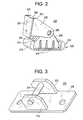
- FIG. 2 is a drawing of an exemplary rotary strut as described herein.
- rotary strut 220 includes a rotary strut base 224 and a rotary strut leg 226 that are attached to one another by rotary strut pin 225 so that rotary strut leg 226 may rotate about rotary strut pin 225.
- rotary strut pin 225 is a hollow, cylindrical pin.
- Rotary strut leg 226 includes a rotary strut flange 228 with holes (as shown) or studs (not shown) that are positioned to facilitate attachment of rotary strut 220 to a first flange of a case section in a desired position and orientation. As shown in FIG.
- Rotary strut base 224 is attached to, and supported by, rotary strut foot 222.
- Rotary strut foot 222 may also incorporate a resilient and/or traction-enhancing material such as rubber to reduce slipping between rotary strut foot 222 and an adjacent supporting surface and to help prevent damage to the surface or to an attached case segment.
- Rotary strut foot 222 may be relatively large in area so as to distribute the weight it bears, and that weight may be transmitted to rotary strut base 224 via a plurality of members 216.
- Rotary strut foot 222 may also include curved nose 218 and heel 219 segments for improved safety.
- rotary strut leg 226 comprises two plates 202, 204 that are parallel and separated by a block 206.
- Rotary strut base 224 similarly comprises two parallel plates 212, 214, which are mounted between plates 202, 204.
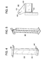
- an exemplary rotating connector 370 is configured to accommodate attachment of a rope or other tension member to help support the weight of a rotatable case part.
- rotating connector 370 includes a connector flange 378 for attaching rotating connector 370 to a second flange of a case part.
- rotating connector 370 includes a pair of side rails 372, 373, between which a rod 374 is supported.
- a rope or other flexible tension member may be passed through rotating connector 370 and manipulated, either by hand or with the assistance of a manual or automatic device, to apply a force to rotating connector 370.
- an exemplary fixed support strut 400 is configured for attaching to and supporting the weight of a rotatable case part.
- strut 400 includes a strut flange 448 to facilitate attachment of strut 400 to a flange of a rotatable case part.
- strut flange 448 may comprise PTFE or another similar non-stick material to resist causing damage to the flange at the point of attachment.
- strut 400 includes a strut foot 442.
- strut 400 includes a strut leg 446, which comprises an I-shaped cross section with an integral stiffening web (not shown).
- Strut leg 446 is configured to help support a case section when fully rotated into a desired orientation, such as a vertical orientation.
- a desired orientation such as a vertical orientation.
- the length of strut 400 is such that strut foot 442 contacts a supporting surface as attached case section is in a substantially vertical orientation.
- an exemplary stabilizer 500 is configured to attach to two or more struts so as to maintain the position and/or orientation of each strut.
- Stabilizer 500 includes an I-shaped cross-section with mounting flanges at its two ends.
- an exemplary lifting connector 600 comprises a plate 610 that defines a hook receiver 620, thus being configured to accommodate attachment of a tension member.
- lifting connector 600 and configured for attachment to a strut via a flange 630.
- Lifting connector 600 is sufficiently strong to support the weight of a rotatable case part.
- flange 630 may be configured for attachment to a first flange of a rotatable case part. To accomplish that, a pattern of holes or studs in flange 630 matches a complementary hole or stud pattern in the first flange.
- Flange 630 may also be configured for attachment directly to a web of a rotatable case part.
- Rotatable power-plant case section 700 is shown in a horizontal orientation.
- Rotatable power-plant case section 700 is supported by a pair of wooden skids 710 on supporting surface 720.
- Rotatable power-plant case section 700 includes three rotating connectors 731, 732, and 733 and one lifting connector 734.
- Rotating connector 732 is attached to second flange 713 at or near front flange midpoint 714.
- Lifting connector 734 is attached to first flange 716 at or near first flange midpoint 717.
- Rotary struts 730 and 740 are attached to endpoints 731, 732 of first flange 716.
- Rotary struts 730 and 740 are positioned so that their axes of rotation are parallel and their feet are closely proximate or touching supporting surface 720.
- a hoist supports tension members 741, 742, 743, and 744, which extend to rotating connectors 731, 732, and 733 and lifting connector 734.
- Rotatable power-plant case section 700 also includes a fixed support strut 750 attached to first flange 716 at or near midpoint 717.
- Secondary strut 760 is also attached to first flange 716.
- a third strut (not shown) is attached to first flange 716 on the other side of midpoint 717 from secondary strut 760.
- an operator may use a mobile crane, a chain block, a pulley system, or another hoist 780 so as to apply a lifting force to raise the rotatable power-plant case section 700 above the wooden skids 710.
- the operator may also manipulate tension members 741, 742, 743, and 744 using a chain block, come-along, or other known apparatus, and may thereby apply a rotating force to rotating connectors 731, 732, and 733 so as to rotate power-plant case section 700 into a desired orientation, such as a vertical orientation where the feet of each strut is contacting the supporting surface 720.
- a chain block can be effective for slow manipulation of the rotating force, and thus the slow manipulation of the orientation of case part 710.
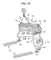
- an exemplary rotatable power-plant case section 800 is supported in a horizontal orientation by a wooden skid 810 on supporting surface 820.
- Rotatable power-plant case section 800 includes three rotating connectors 831, 832, and 833 and one lifting connector 834.
- Rotating connectors 831, 832, and 833 are attached to second flange 813, and lifting connector 834 is attached to first flange 816.
- Rotary strut 830 is attached to first flange 816.
- Rotatable power-plant case section 800 also includes a fixed support strut 850 attached to first flange 816 at or near its midpoint. Secondary strut 860 is also attached to first flange 816.
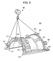
- an exemplary rotatable power-plant case section 900 is supported in a horizontal orientation by a pair of wooden skids 910 as well as a number of tension members that couple hoist 980 to rotating connectors 931, 932, and 933 and to lifting connector 934.
- Rotating connectors 931, 932, and 933 are attached to second flange 913, and lifting connector 934 is attached to first flange 916.
- Rotary strut 930 is attached to an end of first flange 916.
- Rotatable power-plant case section 900 also includes a fixed support strut 950 attached to first flange 916 at or near its midpoint. Secondary strut 960 is also attached to first flange 916.
- an exemplary rotatable power-plant case section 700 is shown in a substantially vertical orientation.
- Rotatable power-plant case section 700 has been rotated so that it no longer lies upon the pair of wooden skids 710, instead being supported by rotary struts 730 and 740, fixed support strut 750, and secondary struts 760, all of which are attached to first flange 716.
- Three rotating connectors 731, 732, and 733 remain in connection with tension members 742, 743, and 744 while tension member 741, which had been applying tensile force to lifting connector 734, has been released.
- Axis of rotation of rotary struts 730 and 740 remain parallel.
Landscapes
- Engineering & Computer Science (AREA)
- Mechanical Engineering (AREA)
- General Engineering & Computer Science (AREA)
- Other Liquid Machine Or Engine Such As Wave Power Use (AREA)
- Tents Or Canopies (AREA)
- Cultivation Receptacles Or Flower-Pots, Or Pots For Seedlings (AREA)
Applications Claiming Priority (1)
| Application Number | Priority Date | Filing Date | Title |
|---|---|---|---|
| TR201107015 | 2011-07-15 |
Publications (1)
| Publication Number | Publication Date |
|---|---|
| EP2546458A2 true EP2546458A2 (de) | 2013-01-16 |
Family
ID=46603575
Family Applications (1)
| Application Number | Title | Priority Date | Filing Date |
|---|---|---|---|
| EP12176509A Withdrawn EP2546458A2 (de) | 2011-07-15 | 2012-07-16 | Drehbarer Kraftwerkgehäuseabschnitt |
Country Status (3)
| Country | Link |
|---|---|
| US (1) | US20130015752A1 (de) |
| EP (1) | EP2546458A2 (de) |
| CN (1) | CN102877947A (de) |
Families Citing this family (2)
| Publication number | Priority date | Publication date | Assignee | Title |
|---|---|---|---|---|
| US20140356152A1 (en) * | 2013-06-04 | 2014-12-04 | General Electric Company | Apparatus for moving turbine shell |
| EP2851522A1 (de) * | 2013-09-19 | 2015-03-25 | Siemens Aktiengesellschaft | Drehvorrichtung für eine Gasturbine und Verfahren zum Drehen eines Bauteils |
Family Cites Families (13)
| Publication number | Priority date | Publication date | Assignee | Title |
|---|---|---|---|---|
| US2703252A (en) * | 1952-04-02 | 1955-03-01 | Rohr Aircraft Corp | Multiple tilting arc support |
| US3128036A (en) * | 1960-10-17 | 1964-04-07 | Le Roy C Mcbride | Machine to generate and control an airstream |
| GB969806A (en) * | 1962-05-16 | 1964-09-16 | Rolls Royce | Improvements relating to the installation of jet engines in engine bays |
| US3628884A (en) * | 1970-06-26 | 1971-12-21 | Westinghouse Electric Corp | Method and apparatus for supporting an inner casing structure |
| NZ241415A (en) * | 1992-01-27 | 1995-04-27 | Air New Zealand Ltd | Gas turbine engine transporting frames |
| US5645389A (en) * | 1995-11-30 | 1997-07-08 | Stanley Aviation Corporation | Shipping frame from fan section of aircraft engine |
| JP4243151B2 (ja) * | 2003-07-10 | 2009-03-25 | 本田技研工業株式会社 | エンジン駆動式発電機 |
| FR2879695B1 (fr) * | 2004-12-16 | 2007-04-06 | Snecma Moteurs Sa | Dispositif de liaison, de longueur ajustable, entre deux pieces |
| ITMI20052506A1 (it) * | 2005-12-28 | 2007-06-29 | Nuovo Pignone Spa | Elemento di appoggio per un compressore o una turbina |
| US8083471B2 (en) * | 2007-01-22 | 2011-12-27 | General Electric Company | Turbine rotor support apparatus and system |
| US8312726B2 (en) * | 2007-12-21 | 2012-11-20 | United Technologies Corp. | Gas turbine engine systems involving I-beam struts |
| CN201215028Y (zh) * | 2008-05-12 | 2009-04-01 | 上海宝冶建设有限公司 | 透平机组上机壳吊装的专用吊耳 |
| US8142150B2 (en) * | 2009-03-06 | 2012-03-27 | General Electric Company | Alignment device for gas turbine casings |
-
2012
- 2012-06-04 US US13/487,489 patent/US20130015752A1/en not_active Abandoned
- 2012-07-13 CN CN2012102425628A patent/CN102877947A/zh active Pending
- 2012-07-16 EP EP12176509A patent/EP2546458A2/de not_active Withdrawn
Non-Patent Citations (1)
| Title |
|---|
| None |
Also Published As
| Publication number | Publication date |
|---|---|
| US20130015752A1 (en) | 2013-01-17 |
| CN102877947A (zh) | 2013-01-16 |
Similar Documents
| Publication | Publication Date | Title |
|---|---|---|
| EP3211187B1 (de) | Positionierungssystem zum ausrichten industrieller maschinenkupplungselemente | |
| CN103061506B (zh) | 一种钢结构穹顶的施工方法 | |
| KR101707360B1 (ko) | 고정 날개 고리의 설치와 분리 방법 및 이 방법에 사용하는 고정 날개 세그먼트 보조 지지 장치 | |
| JP5215403B2 (ja) | 回転電機の分解装置および分解方法 | |
| CN109610330B (zh) | 一种架桥机过孔方法 | |
| US20160251201A1 (en) | Apparatus, system, and method for pipe modular lift system | |
| US20250002305A1 (en) | Wind turbine tower installation apparatus and method | |
| EP2546458A2 (de) | Drehbarer Kraftwerkgehäuseabschnitt | |
| US10830104B2 (en) | Exhaust collector railing removal tool | |
| JP2017529467A (ja) | 橋梁のための作業用プラットホームを支持するための足場 | |
| US10711651B2 (en) | Rotating device for a gas turbine and method for rotating a component | |
| KR101066243B1 (ko) | 주탑 설치장치 및 이를 이용한 주탑 가설공법 | |
| JP2013052853A (ja) | メイン・ローター整備用機具 | |
| EP3203040B1 (de) | Hebevorrichtung für ein turbinegehäuse und verfahren zum heben des gehäuses | |
| JP6751298B2 (ja) | タービンケーシング回転装置 | |
| US20140356152A1 (en) | Apparatus for moving turbine shell | |
| US12095317B1 (en) | Method and system for handling a rotary machine | |
| CN112012890B (zh) | 连接组件、拉索式塔架以及风力发电机组 | |
| CN110494256B (zh) | 用于安装和/或拆卸的方法、应用于该方法的设备、燃烧器适配器、过渡部适配器、装置以及机器人的应用 | |
| JP2023015632A (ja) | 塔状構造物の解体方法 | |
| CN115163227B (zh) | 一种汽轮机波纹膨胀节拆卸辅助装置以及拆卸方法 | |
| KR102751744B1 (ko) | 터빈 로터 검사 장치 | |
| CN111776957A (zh) | 一种支腿高度可调的门式起重机及其施工方法 | |
| CN111989484A (zh) | 液压蓄积器更换工具 | |
| CN121134570A (zh) | 一种用于环行桥式起重机吊装的吊装工具及吊装方法 |
Legal Events
| Date | Code | Title | Description |
|---|---|---|---|
| PUAI | Public reference made under article 153(3) epc to a published international application that has entered the european phase |
Free format text: ORIGINAL CODE: 0009012 |
|
| AK | Designated contracting states |
Kind code of ref document: A2 Designated state(s): AL AT BE BG CH CY CZ DE DK EE ES FI FR GB GR HR HU IE IS IT LI LT LU LV MC MK MT NL NO PL PT RO RS SE SI SK SM TR |
|
| AX | Request for extension of the european patent |
Extension state: BA ME |
|
| STAA | Information on the status of an ep patent application or granted ep patent |
Free format text: STATUS: THE APPLICATION IS DEEMED TO BE WITHDRAWN |
|
| 18D | Application deemed to be withdrawn |
Effective date: 20160202 |