EP2546462A2 - Trou pour système de refroidissement de composant tournant - Google Patents
Trou pour système de refroidissement de composant tournant Download PDFInfo
- Publication number
- EP2546462A2 EP2546462A2 EP12175264A EP12175264A EP2546462A2 EP 2546462 A2 EP2546462 A2 EP 2546462A2 EP 12175264 A EP12175264 A EP 12175264A EP 12175264 A EP12175264 A EP 12175264A EP 2546462 A2 EP2546462 A2 EP 2546462A2
- Authority
- EP
- European Patent Office
- Prior art keywords
- rotor
- holes
- disk
- annular body
- hub
- Prior art date
- Legal status (The legal status is an assumption and is not a legal conclusion. Google has not performed a legal analysis and makes no representation as to the accuracy of the status listed.)
- Granted
Links
Images


Classifications
-
- F—MECHANICAL ENGINEERING; LIGHTING; HEATING; WEAPONS; BLASTING
- F01—MACHINES OR ENGINES IN GENERAL; ENGINE PLANTS IN GENERAL; STEAM ENGINES
- F01D—NON-POSITIVE DISPLACEMENT MACHINES OR ENGINES, e.g. STEAM TURBINES
- F01D5/00—Blades; Blade-carrying members; Heating, heat-insulating, cooling or antivibration means on the blades or the members
- F01D5/02—Blade-carrying members, e.g. rotors
- F01D5/08—Heating, heat-insulating or cooling means
- F01D5/081—Cooling fluid being directed on the side of the rotor disc or at the roots of the blades
- F01D5/082—Cooling fluid being directed on the side of the rotor disc or at the roots of the blades on the side of the rotor disc
-
- F—MECHANICAL ENGINEERING; LIGHTING; HEATING; WEAPONS; BLASTING
- F01—MACHINES OR ENGINES IN GENERAL; ENGINE PLANTS IN GENERAL; STEAM ENGINES
- F01D—NON-POSITIVE DISPLACEMENT MACHINES OR ENGINES, e.g. STEAM TURBINES
- F01D5/00—Blades; Blade-carrying members; Heating, heat-insulating, cooling or antivibration means on the blades or the members
- F01D5/02—Blade-carrying members, e.g. rotors
- F01D5/08—Heating, heat-insulating or cooling means
- F01D5/085—Heating, heat-insulating or cooling means cooling fluid circulating inside the rotor
- F01D5/087—Heating, heat-insulating or cooling means cooling fluid circulating inside the rotor in the radial passages of the rotor disc
Definitions
- Gas turbine engines operate by passing a volume of high energy gases through a plurality of stages of vanes and blades, each having an airfoil, in order to drive turbines to produce rotational shaft power.
- the shaft power is used to drive a compressor to provide compressed air to a combustion process to generate the high energy gases. Additionally, the shaft power is used to drive a generator for producing electricity.
- it is necessary to combust the air at elevated temperatures and to compress the air to elevated pressures, which again increases the temperature.
- the vanes and blades are subjected to extremely high temperatures, often times exceeding the melting point of the alloys comprising the airfoils.
- the present invention is directed toward a rotor for a gas turbine engine.
- the rotor comprises an annular body and a plurality of holes.
- the annular body is configured to rotate in a circumferential direction about an axis extending through a center of the annular body.
- the annular body comprises an outer diameter surface and an inner diameter surface.
- the plurality of holes extends through the annular body.
- Each of the holes comprises an elongate profile in the circumferential direction, and a side wall extending between the outer diameter surface and the inner diameter surface. The side wall is slanted in the circumferential direction.
- FIG. 1 shows gas turbine engine 10, in which the slanted racetrack holes of an embodiment of the present invention can be used.
- Gas turbine engine 10 comprises a dual-spool turbofan engine having fan 12, low pressure compressor (LPC) 14, high pressure compressor (HPC) 16, combustor section 18, high pressure turbine (HPT) 20 and low pressure turbine (LPT) 22, which are each concentrically disposed around longitudinal engine centerline CL.
- Fan 12 is enclosed at its outer diameter within fan case 23A.
- the other engine components are correspondingly enclosed at their outer diameters within various engine casings, including LPC case 23B, HPC case 23C, HPT case 23D and LPT case 23E such that an air flow path is formed around centerline CL.
- turbofan engine Although depicted as a dual-spool turbofan engine in the disclosed nonlimiting embodiment, it should be understood that the concepts described herein are not limited to use with turbofans as the teachings may be applied to other types of turbine engines, such as three-spool turbine engines and geared turbine fan engines.
- Inlet air A enters engine 10 and it is divided into streams of primary air Ap and bypass air A B after it passes through fan 12.
- Fan 12 is rotated by low pressure turbine 22 through shaft 24 (directly or via a transmission (not shown, also known as a gear box) to accelerate bypass air A B through exit guide vanes 26, thereby producing a major portion of the thrust output of engine 10.
- Shaft 24 is supported within engine 10 at ball bearing 25A, roller bearing 25B and roller bearing 25C.
- Primary air A P (also known as gas path air) is directed first into low pressure compressor (LPC) 14 and then into high pressure compressor (HPC) 16.
- LPC 14 and HPC 16 work together to incrementally step up the pressure of primary air Ap.
- HPC 16 is rotated by HPT 20 through shaft 28 to provide compressed air to combustor section 18.
- Shaft 28 is supported within engine 10 at ball bearing 25D and roller bearing 25E.
- the compressed air is delivered to combustors 18A and 18B, along with fuel through injectors 30A and 30B, such that a combustion process can be carried out to produce the high energy gases necessary to turn turbines 20 and 22.
- Primary air A P continues through gas turbine engine 10 whereby it is typically passed through an exhaust nozzle to further produce thrust.
- HPT 20 and LPT 22 each include a circumferential array of blades extending radially from rotors 31 A and 31B connected to shafts 28 and 24, respectively.
- HPT 20 and LPT 22 each include a circumferential array of vanes extending radially from HPT case 23D and LPT case 23E, respectively.
- HPT 20 comprises a two-stage turbine having blades 32A and 32B extending from rotor disks 34A and 34B of rotor 31A. Vane 34A extends radially inward from case HPT case 23E between blades 34A and 34B.
- Blades 32A and 32B include internal passages into which compressed cooling air A C from, for example, HPC 16 is directed to provide cooling relative to the hot combustion gasses of primary air Ap.
- Rotor disks 34A and 34B include holes to permit cooling air A C (also known as secondary air) into roots of blades 32A and 32B.
- rotor disk 34B includes a hub having racetrack cooling holes with angled wall of an embodiment of the present invention.
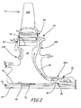
- FIG. 2 is a cross-sectional view of second stage turbine rotor disk 34B of FIG. 1 having disk 36 and hub 38 through which slanted racetrack holes 40 extend.
- Disk 36 includes outer diameter end 42 (shown in FIG. 3 ) into which a plurality of slots 44 extend.
- Disk 36 also includes inner diameter end 46 through which engine centerline CL ( FIG. 1 ) extends.
- Hub 38 extends axially from disk 36 at inner diameter end 46 to form an annular body surrounding centerline CL.
- Rotor disk 34B also includes mini-disk 48, which includes axially extending portion 48A and radially extending portion 48B. Mini-disk 48 forms cooling passage 50 along rotor disk 34B.
- Mini-disk 48 is coupled to hub 38 at lap joint 52, which comprises a pair of overlapping flanges from hub 38 and axially extending portion 48A.
- Mini-disk 48 adjoins outer diameter end 42 at face seal 54, which comprises a flat, sealed plate that abuts slots 44 and roots of blade 32B.
- Rotor disk 34B when rotated during operation of engine 10 via high pressure shaft 28, rotates into the plane of the page of FIG. 2 .
- Low pressure shaft 24 rotates within high pressure shaft 28.
- Rotor disk 34B is coupled to high pressure shaft 28 such that cooling passage 56 is provided therebetween. Cooling air A C from HPC 16 ( FIG. 1 ) is routed into cooling passage 56 where, due to pressure differentials within engine 10, the air turns to enter holes 40.
- cooling air A C flows toward face seal 54, which prevents cooling air A C from escaping rotor disk 34B, and into slots 44. From slots 44 cooling air A C enters inner diameter cooling channels of blade 32B to cool blade 32B relative to primary air Ap. Holes 40 are shaped to facilitate the turning and bending of cooling air A C and reduce pressure losses within engine 10.
- FIG. 3 is a perspective view of second stage turbine rotor 34B of FIG. 2 showing the configuration of slanted racetrack holes 40 in hub 38.
- rotor disk 34B include disk 36 and hub 38, through which holes 40 extend.
- Disk 36 includes outer diameter end 42 into which slots 44 extend.
- Slots 44 include dovetail or fir tree grooves, as are known in the art, to receive root portions of turbine blades. The bottom, or radially inner portions, of slots 44 receive cooling air A C from holes 40 to cool the turbine blades.
- Holes 40 each include walls 58 that produce an elongate profile in the circumferential direction and that are slanted or angled in the circumferential direction into the direction of rotation.
- holes 40 have a racetrack profile, although other shapes may be used. Holes 40 are disposed in a circumferential row spaced evenly about hub 38. Holes 40 reduce the surface area of hub 38, thereby increasing the area through which cooling air A C is able to pass and reducing the pressure loss generated by rotor disk 34B.
- the swirl ratio comprises the swirl velocity of the cooling air divided by the speed of the rotor, which is a product of the rotational speed ⁇ of the rotor and the distance of the hole from the engine centerline.
- Holes 40 of the present invention reduce pressure loss, as compared to straight circular holes, by slanting the holes in a flow rotating direction to reduce the flow turning loss, and elongating the shape of the holes in the flow rotating direction to increase the swirl ratio.
- FIG. 4A is a top view of slanted racetrack hole 40 of FIG. 3 showing a profile of the racetrack shape.
- FIG. 4B is a cross-sectional view of slanted racetrack hole 40 as taken at section 4B-4B of FIG. 4A showing radial angle ⁇ of slanted walls 58 of racetrack hole 40.
- Holes 40 extend from inner diameter surface 60A to outer diameter surface 60B of hub 38.
- Hole 40 includes leading edge wall 62A, trailing edge wall 62B, first side wall 62C and second side wall 62D.
- Rotor disk 34B rotates in the circumferential direction, indicated by arrow ⁇ . Cooling air A C flows downstream with respect to engine 10 ( FIG. 1 ) in an axial direction, then turns generally radially outward in radial direction R before bending in the circumferential direction ⁇ .
- holes 40 are racetrack shaped such that leading edge wall 62A and trailing edge wall 62B are semi-circular, and side walls 62C and 62C extend straight between walls 62A and 62B parallel to each other.
- leading edge wall 62A and 62B may have some other arcuate shape.
- the leading and trailing edge walls may be straight or flat.
- the distance between leading edge and trailing edge side walls 62A and 62B (width) is greater than the distance between side walls 62C and 62D (length) such that holes 40 are elongate in circumferential direction ⁇ .
- hole 40 is approximately twice as wide as it is long, with reference to FIG.
- Walls 58 which include walls 62A-62D, are angled in circumferential direction ⁇ with respect to radial direction R.
- leading edge wall 62A and trailing edge wall 62B are angled in the circumferential direction ⁇ by about thirty degrees to form angle ⁇ .
- angle ⁇ can be anywhere from approximately fifteen degrees to approximately seventy-five degrees, with higher angles typically being used in rotors that rotate at higher speeds.
- leading edge wall 62A angles toward the interior of hole 40, while trailing edge wall 62B angles away from hole 40.
- Side walls 62C and 62D extend straight between outer diameter surface 60B and inner diameter surface 62A.
- cooling air A C is shown as having to bend approximately sixty degrees to bend from the angle of hole 40 to the circumferential direction.
- angle ⁇ rages from about twenty degrees to about fifty degrees
- cooling air A C has to bend about seventy to about forty degrees.
- the cooling air has to bend ninety degrees to change from the true radial direction of the hole to the circumferential direction. As such, pressure losses are reduced by reducing the amount of redirection cooling air A C must undergo to move from cooling passage 56 to cooling passage 50 ( FIG. 2 ).
- FIG. 4C is an alternative cross-sectional view of slanted racetrack hole 40 as taken at section 4B-4B of FIG. 4A showing a contoured shape of slanted walls 64A and 64B of racetrack hole 40.
- Sidewall 64C extends between leading edge wall 64A and trailing edge wall 64B.
- hole 40 is positioned between inner diameter surface 60A and outer diameter surface 60B of hub 38, as in the embodiment of FIG. 4B .
- hole 40 includes leading edge wall 64A and trailing edge wall 64B which are contoured in the radial direction as well as being slanted in the radial direction.
- hole 40 extends through hub 38 at a varying angle ⁇ which still results in an overall slanted configuration.
- walls 64A and 64B extend over single smooth arcs such that angle ⁇ increases, resulting in a convex inflection point between inner diameter surface 60A and outer diameter surface 60B of wall 64B and a concave inflection point on wall 64A.
- walls 64A and 64B may have other contoured or arcuate configurations, such bending or inflecting closer to either inner diameter surface 60A or outer diameter surface 60B.
- wall 64A may be convex and wall 64B may be concave, or vice versa.
- Sidewall 66C and an opposing equivalent sidewall connect slanted walls 64A and 64B.
- the sidewall are parallel and extend straight between walls 64A and 64B.
- cooling air A C bends within hole 40 before passing along disk 36 ( FIG. 2 ), thus further reducing pressure losses.
- Some of the benefits of the present invention in rotating annular bodies include reduction in pressure loss through holes, and increase in the swirl ratio through holes. This is achieved by elongating the hole to a racetrack configuration and slanting the hole in a radial direction about thirty to about forty degrees, in one embodiment. These qualities increase flow area, reduce flow vector turning and overall pressure loss, as compared to straight circular holes.
- the swirl ratio of cooling air for the present invention is greater than one, whereas circular holes are limited to swirl ratios of unity. Thus, the swirl ratio can be increased to 1.2 or more, a 20% or more increase as compared to the straight circular holes.
Landscapes
- Engineering & Computer Science (AREA)
- Mechanical Engineering (AREA)
- General Engineering & Computer Science (AREA)
- Turbine Rotor Nozzle Sealing (AREA)
Applications Claiming Priority (1)
| Application Number | Priority Date | Filing Date | Title |
|---|---|---|---|
| US13/184,035 US20130017059A1 (en) | 2011-07-15 | 2011-07-15 | Hole for rotating component cooling system |
Publications (3)
| Publication Number | Publication Date |
|---|---|
| EP2546462A2 true EP2546462A2 (fr) | 2013-01-16 |
| EP2546462A3 EP2546462A3 (fr) | 2014-02-26 |
| EP2546462B1 EP2546462B1 (fr) | 2015-04-01 |
Family
ID=46750163
Family Applications (1)
| Application Number | Title | Priority Date | Filing Date |
|---|---|---|---|
| EP12175264.6A Not-in-force EP2546462B1 (fr) | 2011-07-15 | 2012-07-06 | Trou pour système de refroidissement de composant tournant |
Country Status (2)
| Country | Link |
|---|---|
| US (1) | US20130017059A1 (fr) |
| EP (1) | EP2546462B1 (fr) |
Cited By (1)
| Publication number | Priority date | Publication date | Assignee | Title |
|---|---|---|---|---|
| EP3260657A1 (fr) * | 2016-06-23 | 2017-12-27 | United Technologies Corporation | Mini-disque pour moteur à turbine à gaz |
Families Citing this family (6)
| Publication number | Priority date | Publication date | Assignee | Title |
|---|---|---|---|---|
| EP3266025B1 (fr) * | 2015-03-05 | 2019-10-09 | Westinghouse Electric Company Llc | Système de borication mobile |
| EP3342979B1 (fr) * | 2016-12-30 | 2020-06-17 | Ansaldo Energia Switzerland AG | Turbine à gaz comportant des disques de rotor refroidis |
| US10794190B1 (en) * | 2018-07-30 | 2020-10-06 | Florida Turbine Technologies, Inc. | Cast integrally bladed rotor with bore entry cooling |
| CN114961893B (zh) * | 2021-02-24 | 2023-08-04 | 中国航发商用航空发动机有限责任公司 | 航空发动机减涡器引气装置及航空发动机 |
| US12012870B1 (en) * | 2022-11-29 | 2024-06-18 | Rtx Corporation | Machinable coating for CMC and metal interface in a turbine section |
| US12359575B2 (en) | 2022-12-13 | 2025-07-15 | Rtx Corporation | Machinable coating with thermal protection |
Family Cites Families (8)
| Publication number | Priority date | Publication date | Assignee | Title |
|---|---|---|---|---|
| US885108A (en) * | 1907-01-21 | 1908-04-21 | Simeon V Trent | Centrifugal pump. |
| US4203705A (en) * | 1975-12-22 | 1980-05-20 | United Technologies Corporation | Bonded turbine disk for improved low cycle fatigue life |
| US4484860A (en) * | 1982-05-17 | 1984-11-27 | Donaldson Company, Inc. | Radial tube centrifugal fan |
| US4674955A (en) * | 1984-12-21 | 1987-06-23 | The Garrett Corporation | Radial inboard preswirl system |
| FR2614654B1 (fr) * | 1987-04-29 | 1992-02-21 | Snecma | Disque de compresseur axial de turbomachine a prelevement d'air centripete |
| GB2420155B (en) * | 2004-11-12 | 2008-08-27 | Rolls Royce Plc | Turbine blade cooling system |
| US7708519B2 (en) * | 2007-03-26 | 2010-05-04 | Honeywell International Inc. | Vortex spoiler for delivery of cooling airflow in a turbine engine |
| JP4981709B2 (ja) * | 2008-02-28 | 2012-07-25 | 三菱重工業株式会社 | ガスタービン及びディスク並びにディスクの径方向通路形成方法 |
-
2011
- 2011-07-15 US US13/184,035 patent/US20130017059A1/en not_active Abandoned
-
2012
- 2012-07-06 EP EP12175264.6A patent/EP2546462B1/fr not_active Not-in-force
Non-Patent Citations (1)
| Title |
|---|
| None |
Cited By (2)
| Publication number | Priority date | Publication date | Assignee | Title |
|---|---|---|---|---|
| EP3260657A1 (fr) * | 2016-06-23 | 2017-12-27 | United Technologies Corporation | Mini-disque pour moteur à turbine à gaz |
| US10400603B2 (en) | 2016-06-23 | 2019-09-03 | United Technologies Corporation | Mini-disk for gas turbine engine |
Also Published As
| Publication number | Publication date |
|---|---|
| EP2546462A3 (fr) | 2014-02-26 |
| EP2546462B1 (fr) | 2015-04-01 |
| US20130017059A1 (en) | 2013-01-17 |
Similar Documents
| Publication | Publication Date | Title |
|---|---|---|
| EP2546462B1 (fr) | Trou pour système de refroidissement de composant tournant | |
| US10830073B2 (en) | Vane assembly of a gas turbine engine | |
| US8807945B2 (en) | Cooling system for turbine airfoil including ice-cream-cone-shaped pedestals | |
| EP3187712B1 (fr) | Admission courte de nacelle | |
| EP2557270B1 (fr) | Aube comprenant une tranchée avec surface profilée | |
| US20120272663A1 (en) | Centrifugal compressor assembly with stator vane row | |
| EP3460181A1 (fr) | Ensemble rotor de tambour extérieur | |
| US9920633B2 (en) | Compound fillet for a gas turbine airfoil | |
| US9932834B2 (en) | Rotor blade with a conic spline fillet at an intersection between a platform and a neck | |
| US9546556B2 (en) | Turbine blade root profile | |
| US9347323B2 (en) | Gas turbine engine airfoil total chord relative to span | |
| US20220018293A1 (en) | Compressor apparatus with bleed slot and supplemental flange | |
| US20190154050A1 (en) | Rotor hub seal | |
| US20170030213A1 (en) | Turbine section with tip flow vanes | |
| US12270317B2 (en) | Airfoils for gas turbine engines | |
| CN107762564A (zh) | 带有多孔肋部的用于涡轮发动机的翼型件 | |
| US10633992B2 (en) | Rim seal | |
| US20160326894A1 (en) | Airfoil cooling passage | |
| US20210095596A1 (en) | Multi-flow cooling circuit for gas turbine engine flowpath component | |
| US12352181B2 (en) | Turbine airfoils |
Legal Events
| Date | Code | Title | Description |
|---|---|---|---|
| PUAI | Public reference made under article 153(3) epc to a published international application that has entered the european phase |
Free format text: ORIGINAL CODE: 0009012 |
|
| AK | Designated contracting states |
Kind code of ref document: A2 Designated state(s): AL AT BE BG CH CY CZ DE DK EE ES FI FR GB GR HR HU IE IS IT LI LT LU LV MC MK MT NL NO PL PT RO RS SE SI SK SM TR |
|
| AX | Request for extension of the european patent |
Extension state: BA ME |
|
| PUAL | Search report despatched |
Free format text: ORIGINAL CODE: 0009013 |
|
| AK | Designated contracting states |
Kind code of ref document: A3 Designated state(s): AL AT BE BG CH CY CZ DE DK EE ES FI FR GB GR HR HU IE IS IT LI LT LU LV MC MK MT NL NO PL PT RO RS SE SI SK SM TR |
|
| AX | Request for extension of the european patent |
Extension state: BA ME |
|
| RIC1 | Information provided on ipc code assigned before grant |
Ipc: F01D 5/08 20060101AFI20140117BHEP |
|
| 17P | Request for examination filed |
Effective date: 20140822 |
|
| RBV | Designated contracting states (corrected) |
Designated state(s): AL AT BE BG CH CY CZ DE DK EE ES FI FR GB GR HR HU IE IS IT LI LT LU LV MC MK MT NL NO PL PT RO RS SE SI SK SM TR |
|
| GRAP | Despatch of communication of intention to grant a patent |
Free format text: ORIGINAL CODE: EPIDOSNIGR1 |
|
| INTG | Intention to grant announced |
Effective date: 20141020 |
|
| GRAS | Grant fee paid |
Free format text: ORIGINAL CODE: EPIDOSNIGR3 |
|
| GRAA | (expected) grant |
Free format text: ORIGINAL CODE: 0009210 |
|
| AK | Designated contracting states |
Kind code of ref document: B1 Designated state(s): AL AT BE BG CH CY CZ DE DK EE ES FI FR GB GR HR HU IE IS IT LI LT LU LV MC MK MT NL NO PL PT RO RS SE SI SK SM TR |
|
| REG | Reference to a national code |
Ref country code: GB Ref legal event code: FG4D |
|
| REG | Reference to a national code |
Ref country code: CH Ref legal event code: EP |
|
| REG | Reference to a national code |
Ref country code: IE Ref legal event code: FG4D |
|
| REG | Reference to a national code |
Ref country code: DE Ref legal event code: R096 Ref document number: 602012006274 Country of ref document: DE Effective date: 20150513 |
|
| REG | Reference to a national code |
Ref country code: AT Ref legal event code: REF Ref document number: 719211 Country of ref document: AT Kind code of ref document: T Effective date: 20150515 |
|
| REG | Reference to a national code |
Ref country code: NL Ref legal event code: VDEP Effective date: 20150401 |
|
| REG | Reference to a national code |
Ref country code: AT Ref legal event code: MK05 Ref document number: 719211 Country of ref document: AT Kind code of ref document: T Effective date: 20150401 |
|
| REG | Reference to a national code |
Ref country code: LT Ref legal event code: MG4D |
|
| PG25 | Lapsed in a contracting state [announced via postgrant information from national office to epo] |
Ref country code: NL Free format text: LAPSE BECAUSE OF FAILURE TO SUBMIT A TRANSLATION OF THE DESCRIPTION OR TO PAY THE FEE WITHIN THE PRESCRIBED TIME-LIMIT Effective date: 20150401 |
|
| PG25 | Lapsed in a contracting state [announced via postgrant information from national office to epo] |
Ref country code: ES Free format text: LAPSE BECAUSE OF FAILURE TO SUBMIT A TRANSLATION OF THE DESCRIPTION OR TO PAY THE FEE WITHIN THE PRESCRIBED TIME-LIMIT Effective date: 20150401 Ref country code: LT Free format text: LAPSE BECAUSE OF FAILURE TO SUBMIT A TRANSLATION OF THE DESCRIPTION OR TO PAY THE FEE WITHIN THE PRESCRIBED TIME-LIMIT Effective date: 20150401 Ref country code: NO Free format text: LAPSE BECAUSE OF FAILURE TO SUBMIT A TRANSLATION OF THE DESCRIPTION OR TO PAY THE FEE WITHIN THE PRESCRIBED TIME-LIMIT Effective date: 20150701 Ref country code: HR Free format text: LAPSE BECAUSE OF FAILURE TO SUBMIT A TRANSLATION OF THE DESCRIPTION OR TO PAY THE FEE WITHIN THE PRESCRIBED TIME-LIMIT Effective date: 20150401 Ref country code: FI Free format text: LAPSE BECAUSE OF FAILURE TO SUBMIT A TRANSLATION OF THE DESCRIPTION OR TO PAY THE FEE WITHIN THE PRESCRIBED TIME-LIMIT Effective date: 20150401 Ref country code: PT Free format text: LAPSE BECAUSE OF FAILURE TO SUBMIT A TRANSLATION OF THE DESCRIPTION OR TO PAY THE FEE WITHIN THE PRESCRIBED TIME-LIMIT Effective date: 20150803 Ref country code: CZ Free format text: LAPSE BECAUSE OF FAILURE TO SUBMIT A TRANSLATION OF THE DESCRIPTION OR TO PAY THE FEE WITHIN THE PRESCRIBED TIME-LIMIT Effective date: 20150401 |
|
| PG25 | Lapsed in a contracting state [announced via postgrant information from national office to epo] |
Ref country code: LV Free format text: LAPSE BECAUSE OF FAILURE TO SUBMIT A TRANSLATION OF THE DESCRIPTION OR TO PAY THE FEE WITHIN THE PRESCRIBED TIME-LIMIT Effective date: 20150401 Ref country code: RS Free format text: LAPSE BECAUSE OF FAILURE TO SUBMIT A TRANSLATION OF THE DESCRIPTION OR TO PAY THE FEE WITHIN THE PRESCRIBED TIME-LIMIT Effective date: 20150401 Ref country code: IS Free format text: LAPSE BECAUSE OF FAILURE TO SUBMIT A TRANSLATION OF THE DESCRIPTION OR TO PAY THE FEE WITHIN THE PRESCRIBED TIME-LIMIT Effective date: 20150801 Ref country code: GR Free format text: LAPSE BECAUSE OF FAILURE TO SUBMIT A TRANSLATION OF THE DESCRIPTION OR TO PAY THE FEE WITHIN THE PRESCRIBED TIME-LIMIT Effective date: 20150702 Ref country code: AT Free format text: LAPSE BECAUSE OF FAILURE TO SUBMIT A TRANSLATION OF THE DESCRIPTION OR TO PAY THE FEE WITHIN THE PRESCRIBED TIME-LIMIT Effective date: 20150401 |
|
| REG | Reference to a national code |
Ref country code: DE Ref legal event code: R097 Ref document number: 602012006274 Country of ref document: DE |
|
| PG25 | Lapsed in a contracting state [announced via postgrant information from national office to epo] |
Ref country code: EE Free format text: LAPSE BECAUSE OF FAILURE TO SUBMIT A TRANSLATION OF THE DESCRIPTION OR TO PAY THE FEE WITHIN THE PRESCRIBED TIME-LIMIT Effective date: 20150401 Ref country code: DK Free format text: LAPSE BECAUSE OF FAILURE TO SUBMIT A TRANSLATION OF THE DESCRIPTION OR TO PAY THE FEE WITHIN THE PRESCRIBED TIME-LIMIT Effective date: 20150401 |
|
| PLBE | No opposition filed within time limit |
Free format text: ORIGINAL CODE: 0009261 |
|
| STAA | Information on the status of an ep patent application or granted ep patent |
Free format text: STATUS: NO OPPOSITION FILED WITHIN TIME LIMIT |
|
| PG25 | Lapsed in a contracting state [announced via postgrant information from national office to epo] |
Ref country code: SK Free format text: LAPSE BECAUSE OF FAILURE TO SUBMIT A TRANSLATION OF THE DESCRIPTION OR TO PAY THE FEE WITHIN THE PRESCRIBED TIME-LIMIT Effective date: 20150401 Ref country code: MC Free format text: LAPSE BECAUSE OF FAILURE TO SUBMIT A TRANSLATION OF THE DESCRIPTION OR TO PAY THE FEE WITHIN THE PRESCRIBED TIME-LIMIT Effective date: 20150401 Ref country code: RO Free format text: LAPSE BECAUSE OF NON-PAYMENT OF DUE FEES Effective date: 20150401 Ref country code: PL Free format text: LAPSE BECAUSE OF FAILURE TO SUBMIT A TRANSLATION OF THE DESCRIPTION OR TO PAY THE FEE WITHIN THE PRESCRIBED TIME-LIMIT Effective date: 20150401 |
|
| REG | Reference to a national code |
Ref country code: CH Ref legal event code: PL |
|
| 26N | No opposition filed |
Effective date: 20160105 |
|
| PG25 | Lapsed in a contracting state [announced via postgrant information from national office to epo] |
Ref country code: LU Free format text: LAPSE BECAUSE OF FAILURE TO SUBMIT A TRANSLATION OF THE DESCRIPTION OR TO PAY THE FEE WITHIN THE PRESCRIBED TIME-LIMIT Effective date: 20150706 |
|
| REG | Reference to a national code |
Ref country code: IE Ref legal event code: MM4A |
|
| PG25 | Lapsed in a contracting state [announced via postgrant information from national office to epo] |
Ref country code: LI Free format text: LAPSE BECAUSE OF NON-PAYMENT OF DUE FEES Effective date: 20150731 Ref country code: CH Free format text: LAPSE BECAUSE OF NON-PAYMENT OF DUE FEES Effective date: 20150731 Ref country code: IT Free format text: LAPSE BECAUSE OF FAILURE TO SUBMIT A TRANSLATION OF THE DESCRIPTION OR TO PAY THE FEE WITHIN THE PRESCRIBED TIME-LIMIT Effective date: 20150401 |
|
| REG | Reference to a national code |
Ref country code: FR Ref legal event code: ST Effective date: 20160331 |
|
| PG25 | Lapsed in a contracting state [announced via postgrant information from national office to epo] |
Ref country code: SI Free format text: LAPSE BECAUSE OF FAILURE TO SUBMIT A TRANSLATION OF THE DESCRIPTION OR TO PAY THE FEE WITHIN THE PRESCRIBED TIME-LIMIT Effective date: 20150401 Ref country code: FR Free format text: LAPSE BECAUSE OF NON-PAYMENT OF DUE FEES Effective date: 20150731 |
|
| PG25 | Lapsed in a contracting state [announced via postgrant information from national office to epo] |
Ref country code: IE Free format text: LAPSE BECAUSE OF NON-PAYMENT OF DUE FEES Effective date: 20150706 |
|
| PG25 | Lapsed in a contracting state [announced via postgrant information from national office to epo] |
Ref country code: BE Free format text: LAPSE BECAUSE OF FAILURE TO SUBMIT A TRANSLATION OF THE DESCRIPTION OR TO PAY THE FEE WITHIN THE PRESCRIBED TIME-LIMIT Effective date: 20150401 |
|
| PG25 | Lapsed in a contracting state [announced via postgrant information from national office to epo] |
Ref country code: MT Free format text: LAPSE BECAUSE OF FAILURE TO SUBMIT A TRANSLATION OF THE DESCRIPTION OR TO PAY THE FEE WITHIN THE PRESCRIBED TIME-LIMIT Effective date: 20150401 |
|
| PG25 | Lapsed in a contracting state [announced via postgrant information from national office to epo] |
Ref country code: SM Free format text: LAPSE BECAUSE OF FAILURE TO SUBMIT A TRANSLATION OF THE DESCRIPTION OR TO PAY THE FEE WITHIN THE PRESCRIBED TIME-LIMIT Effective date: 20150401 Ref country code: BG Free format text: LAPSE BECAUSE OF FAILURE TO SUBMIT A TRANSLATION OF THE DESCRIPTION OR TO PAY THE FEE WITHIN THE PRESCRIBED TIME-LIMIT Effective date: 20150401 Ref country code: HU Free format text: LAPSE BECAUSE OF FAILURE TO SUBMIT A TRANSLATION OF THE DESCRIPTION OR TO PAY THE FEE WITHIN THE PRESCRIBED TIME-LIMIT; INVALID AB INITIO Effective date: 20120706 |
|
| PG25 | Lapsed in a contracting state [announced via postgrant information from national office to epo] |
Ref country code: CY Free format text: LAPSE BECAUSE OF FAILURE TO SUBMIT A TRANSLATION OF THE DESCRIPTION OR TO PAY THE FEE WITHIN THE PRESCRIBED TIME-LIMIT Effective date: 20150401 Ref country code: SE Free format text: LAPSE BECAUSE OF FAILURE TO SUBMIT A TRANSLATION OF THE DESCRIPTION OR TO PAY THE FEE WITHIN THE PRESCRIBED TIME-LIMIT Effective date: 20150401 |
|
| REG | Reference to a national code |
Ref country code: DE Ref legal event code: R082 Ref document number: 602012006274 Country of ref document: DE Representative=s name: SCHMITT-NILSON SCHRAUD WAIBEL WOHLFROM PATENTA, DE |
|
| REG | Reference to a national code |
Ref country code: DE Ref legal event code: R082 Ref document number: 602012006274 Country of ref document: DE Representative=s name: SCHMITT-NILSON SCHRAUD WAIBEL WOHLFROM PATENTA, DE Ref country code: DE Ref legal event code: R081 Ref document number: 602012006274 Country of ref document: DE Owner name: UNITED TECHNOLOGIES CORP. (N.D.GES.D. STAATES , US Free format text: FORMER OWNER: UNITED TECHNOLOGIES CORP., HARTFORD, CONN., US |
|
| PG25 | Lapsed in a contracting state [announced via postgrant information from national office to epo] |
Ref country code: TR Free format text: LAPSE BECAUSE OF FAILURE TO SUBMIT A TRANSLATION OF THE DESCRIPTION OR TO PAY THE FEE WITHIN THE PRESCRIBED TIME-LIMIT Effective date: 20150401 |
|
| PG25 | Lapsed in a contracting state [announced via postgrant information from national office to epo] |
Ref country code: MK Free format text: LAPSE BECAUSE OF FAILURE TO SUBMIT A TRANSLATION OF THE DESCRIPTION OR TO PAY THE FEE WITHIN THE PRESCRIBED TIME-LIMIT Effective date: 20150401 |
|
| PG25 | Lapsed in a contracting state [announced via postgrant information from national office to epo] |
Ref country code: AL Free format text: LAPSE BECAUSE OF FAILURE TO SUBMIT A TRANSLATION OF THE DESCRIPTION OR TO PAY THE FEE WITHIN THE PRESCRIBED TIME-LIMIT Effective date: 20150401 |
|
| REG | Reference to a national code |
Ref country code: DE Ref legal event code: R081 Ref document number: 602012006274 Country of ref document: DE Owner name: RAYTHEON TECHNOLOGIES CORPORATION (N.D.GES.D.S, US Free format text: FORMER OWNER: UNITED TECHNOLOGIES CORP. (N.D.GES.D. STAATES DELAWARE), FARMINGTON, CONN., US |
|
| P01 | Opt-out of the competence of the unified patent court (upc) registered |
Effective date: 20230520 |
|
| PGFP | Annual fee paid to national office [announced via postgrant information from national office to epo] |
Ref country code: GB Payment date: 20240620 Year of fee payment: 13 |
|
| PGFP | Annual fee paid to national office [announced via postgrant information from national office to epo] |
Ref country code: DE Payment date: 20240619 Year of fee payment: 13 |
|
| REG | Reference to a national code |
Ref country code: DE Ref legal event code: R119 Ref document number: 602012006274 Country of ref document: DE |
|
| GBPC | Gb: european patent ceased through non-payment of renewal fee |
Effective date: 20250706 |
|
| PG25 | Lapsed in a contracting state [announced via postgrant information from national office to epo] |
Ref country code: GB Free format text: LAPSE BECAUSE OF NON-PAYMENT OF DUE FEES Effective date: 20250706 |
|
| PG25 | Lapsed in a contracting state [announced via postgrant information from national office to epo] |
Ref country code: DE Free format text: LAPSE BECAUSE OF NON-PAYMENT OF DUE FEES Effective date: 20260203 |