EP2546491B1 - Échangeur de chaleur de gaz d'échappement de moteur et dispositif d'alimentation en énergie utilisant celui-ci - Google Patents
Échangeur de chaleur de gaz d'échappement de moteur et dispositif d'alimentation en énergie utilisant celui-ci Download PDFInfo
- Publication number
- EP2546491B1 EP2546491B1 EP11753434.7A EP11753434A EP2546491B1 EP 2546491 B1 EP2546491 B1 EP 2546491B1 EP 11753434 A EP11753434 A EP 11753434A EP 2546491 B1 EP2546491 B1 EP 2546491B1
- Authority
- EP
- European Patent Office
- Prior art keywords
- exhaust gas
- apertures
- passage
- heat exchanger
- discharge pipe
- Prior art date
- Legal status (The legal status is an assumption and is not a legal conclusion. Google has not performed a legal analysis and makes no representation as to the accuracy of the status listed.)
- Not-in-force
Links
Images


Classifications
-
- F—MECHANICAL ENGINEERING; LIGHTING; HEATING; WEAPONS; BLASTING
- F01—MACHINES OR ENGINES IN GENERAL; ENGINE PLANTS IN GENERAL; STEAM ENGINES
- F01N—GAS-FLOW SILENCERS OR EXHAUST APPARATUS FOR MACHINES OR ENGINES IN GENERAL; GAS-FLOW SILENCERS OR EXHAUST APPARATUS FOR INTERNAL-COMBUSTION ENGINES
- F01N3/00—Exhaust or silencing apparatus having means for purifying, rendering innocuous, or otherwise treating exhaust
- F01N3/08—Exhaust or silencing apparatus having means for purifying, rendering innocuous, or otherwise treating exhaust for rendering innocuous
- F01N3/10—Exhaust or silencing apparatus having means for purifying, rendering innocuous, or otherwise treating exhaust for rendering innocuous by thermal or catalytic conversion of noxious components of exhaust
- F01N3/24—Exhaust or silencing apparatus having means for purifying, rendering innocuous, or otherwise treating exhaust for rendering innocuous by thermal or catalytic conversion of noxious components of exhaust characterised by constructional aspects of converting apparatus
- F01N3/28—Construction of catalytic reactors
- F01N3/2882—Catalytic reactors combined or associated with other devices, e.g. exhaust silencers or other exhaust purification devices
- F01N3/2889—Catalytic reactors combined or associated with other devices, e.g. exhaust silencers or other exhaust purification devices with heat exchangers in a single housing
-
- F—MECHANICAL ENGINEERING; LIGHTING; HEATING; WEAPONS; BLASTING
- F01—MACHINES OR ENGINES IN GENERAL; ENGINE PLANTS IN GENERAL; STEAM ENGINES
- F01N—GAS-FLOW SILENCERS OR EXHAUST APPARATUS FOR MACHINES OR ENGINES IN GENERAL; GAS-FLOW SILENCERS OR EXHAUST APPARATUS FOR INTERNAL-COMBUSTION ENGINES
- F01N5/00—Exhaust or silencing apparatus combined or associated with devices profiting by exhaust energy
- F01N5/02—Exhaust or silencing apparatus combined or associated with devices profiting by exhaust energy the devices using heat
-
- F—MECHANICAL ENGINEERING; LIGHTING; HEATING; WEAPONS; BLASTING
- F28—HEAT EXCHANGE IN GENERAL
- F28D—HEAT-EXCHANGE APPARATUS, NOT PROVIDED FOR IN ANOTHER SUBCLASS, IN WHICH THE HEAT-EXCHANGE MEDIA DO NOT COME INTO DIRECT CONTACT
- F28D7/00—Heat-exchange apparatus having stationary tubular conduit assemblies for both heat-exchange media, the media being in contact with different sides of a conduit wall
- F28D7/0066—Multi-circuit heat-exchangers, e.g. integrating different heat exchange sections in the same unit or heat-exchangers for more than two fluids
-
- F—MECHANICAL ENGINEERING; LIGHTING; HEATING; WEAPONS; BLASTING
- F28—HEAT EXCHANGE IN GENERAL
- F28D—HEAT-EXCHANGE APPARATUS, NOT PROVIDED FOR IN ANOTHER SUBCLASS, IN WHICH THE HEAT-EXCHANGE MEDIA DO NOT COME INTO DIRECT CONTACT
- F28D7/00—Heat-exchange apparatus having stationary tubular conduit assemblies for both heat-exchange media, the media being in contact with different sides of a conduit wall
- F28D7/10—Heat-exchange apparatus having stationary tubular conduit assemblies for both heat-exchange media, the media being in contact with different sides of a conduit wall the conduits being arranged one within the other, e.g. concentrically
- F28D7/103—Heat-exchange apparatus having stationary tubular conduit assemblies for both heat-exchange media, the media being in contact with different sides of a conduit wall the conduits being arranged one within the other, e.g. concentrically consisting of more than two coaxial conduits or modules of more than two coaxial conduits
-
- F—MECHANICAL ENGINEERING; LIGHTING; HEATING; WEAPONS; BLASTING
- F28—HEAT EXCHANGE IN GENERAL
- F28D—HEAT-EXCHANGE APPARATUS, NOT PROVIDED FOR IN ANOTHER SUBCLASS, IN WHICH THE HEAT-EXCHANGE MEDIA DO NOT COME INTO DIRECT CONTACT
- F28D7/00—Heat-exchange apparatus having stationary tubular conduit assemblies for both heat-exchange media, the media being in contact with different sides of a conduit wall
- F28D7/10—Heat-exchange apparatus having stationary tubular conduit assemblies for both heat-exchange media, the media being in contact with different sides of a conduit wall the conduits being arranged one within the other, e.g. concentrically
- F28D7/106—Heat-exchange apparatus having stationary tubular conduit assemblies for both heat-exchange media, the media being in contact with different sides of a conduit wall the conduits being arranged one within the other, e.g. concentrically consisting of two coaxial conduits or modules of two coaxial conduits
-
- F—MECHANICAL ENGINEERING; LIGHTING; HEATING; WEAPONS; BLASTING
- F28—HEAT EXCHANGE IN GENERAL
- F28F—DETAILS OF HEAT-EXCHANGE AND HEAT-TRANSFER APPARATUS, OF GENERAL APPLICATION
- F28F1/00—Tubular elements; Assemblies of tubular elements
- F28F1/10—Tubular elements and assemblies thereof with means for increasing heat-transfer area, e.g. with fins, with projections, with recesses
-
- F—MECHANICAL ENGINEERING; LIGHTING; HEATING; WEAPONS; BLASTING
- F28—HEAT EXCHANGE IN GENERAL
- F28F—DETAILS OF HEAT-EXCHANGE AND HEAT-TRANSFER APPARATUS, OF GENERAL APPLICATION
- F28F13/00—Arrangements for modifying heat-transfer, e.g. increasing, decreasing
- F28F13/02—Arrangements for modifying heat-transfer, e.g. increasing, decreasing by influencing fluid boundary
-
- F—MECHANICAL ENGINEERING; LIGHTING; HEATING; WEAPONS; BLASTING
- F28—HEAT EXCHANGE IN GENERAL
- F28F—DETAILS OF HEAT-EXCHANGE AND HEAT-TRANSFER APPARATUS, OF GENERAL APPLICATION
- F28F13/00—Arrangements for modifying heat-transfer, e.g. increasing, decreasing
- F28F13/06—Arrangements for modifying heat-transfer, e.g. increasing, decreasing by affecting the pattern of flow of the heat-exchange media
-
- F—MECHANICAL ENGINEERING; LIGHTING; HEATING; WEAPONS; BLASTING
- F28—HEAT EXCHANGE IN GENERAL
- F28F—DETAILS OF HEAT-EXCHANGE AND HEAT-TRANSFER APPARATUS, OF GENERAL APPLICATION
- F28F9/00—Casings; Header boxes; Auxiliary supports for elements; Auxiliary members within casings
- F28F9/02—Header boxes; End plates
- F28F9/0246—Arrangements for connecting header boxes with flow lines
-
- F—MECHANICAL ENGINEERING; LIGHTING; HEATING; WEAPONS; BLASTING
- F01—MACHINES OR ENGINES IN GENERAL; ENGINE PLANTS IN GENERAL; STEAM ENGINES
- F01N—GAS-FLOW SILENCERS OR EXHAUST APPARATUS FOR MACHINES OR ENGINES IN GENERAL; GAS-FLOW SILENCERS OR EXHAUST APPARATUS FOR INTERNAL-COMBUSTION ENGINES
- F01N2260/00—Exhaust treating devices having provisions not otherwise provided for
- F01N2260/08—Exhaust treating devices having provisions not otherwise provided for for preventing heat loss or temperature drop, using other means than layers of heat-insulating material
-
- F—MECHANICAL ENGINEERING; LIGHTING; HEATING; WEAPONS; BLASTING
- F01—MACHINES OR ENGINES IN GENERAL; ENGINE PLANTS IN GENERAL; STEAM ENGINES
- F01N—GAS-FLOW SILENCERS OR EXHAUST APPARATUS FOR MACHINES OR ENGINES IN GENERAL; GAS-FLOW SILENCERS OR EXHAUST APPARATUS FOR INTERNAL-COMBUSTION ENGINES
- F01N2470/00—Structure or shape of exhaust gas passages, pipes or tubes
- F01N2470/02—Tubes being perforated
- F01N2470/04—Tubes being perforated characterised by shape, disposition or dimensions of apertures
-
- F—MECHANICAL ENGINEERING; LIGHTING; HEATING; WEAPONS; BLASTING
- F01—MACHINES OR ENGINES IN GENERAL; ENGINE PLANTS IN GENERAL; STEAM ENGINES
- F01N—GAS-FLOW SILENCERS OR EXHAUST APPARATUS FOR MACHINES OR ENGINES IN GENERAL; GAS-FLOW SILENCERS OR EXHAUST APPARATUS FOR INTERNAL-COMBUSTION ENGINES
- F01N2470/00—Structure or shape of exhaust gas passages, pipes or tubes
- F01N2470/18—Structure or shape of exhaust gas passages, pipes or tubes the axis of inlet or outlet tubes being other than the longitudinal axis of apparatus
-
- F—MECHANICAL ENGINEERING; LIGHTING; HEATING; WEAPONS; BLASTING
- F01—MACHINES OR ENGINES IN GENERAL; ENGINE PLANTS IN GENERAL; STEAM ENGINES
- F01N—GAS-FLOW SILENCERS OR EXHAUST APPARATUS FOR MACHINES OR ENGINES IN GENERAL; GAS-FLOW SILENCERS OR EXHAUST APPARATUS FOR INTERNAL-COMBUSTION ENGINES
- F01N2470/00—Structure or shape of exhaust gas passages, pipes or tubes
- F01N2470/24—Concentric tubes or tubes being concentric to housing, e.g. telescopically assembled
-
- F—MECHANICAL ENGINEERING; LIGHTING; HEATING; WEAPONS; BLASTING
- F28—HEAT EXCHANGE IN GENERAL
- F28D—HEAT-EXCHANGE APPARATUS, NOT PROVIDED FOR IN ANOTHER SUBCLASS, IN WHICH THE HEAT-EXCHANGE MEDIA DO NOT COME INTO DIRECT CONTACT
- F28D21/00—Heat-exchange apparatus not covered by any of the groups F28D1/00 - F28D20/00
- F28D21/0001—Recuperative heat exchangers
- F28D21/0003—Recuperative heat exchangers the heat being recuperated from exhaust gases
-
- F—MECHANICAL ENGINEERING; LIGHTING; HEATING; WEAPONS; BLASTING
- F28—HEAT EXCHANGE IN GENERAL
- F28F—DETAILS OF HEAT-EXCHANGE AND HEAT-TRANSFER APPARATUS, OF GENERAL APPLICATION
- F28F2265/00—Safety or protection arrangements; Arrangements for preventing malfunction
- F28F2265/26—Safety or protection arrangements; Arrangements for preventing malfunction for allowing differential expansion between elements
-
- Y—GENERAL TAGGING OF NEW TECHNOLOGICAL DEVELOPMENTS; GENERAL TAGGING OF CROSS-SECTIONAL TECHNOLOGIES SPANNING OVER SEVERAL SECTIONS OF THE IPC; TECHNICAL SUBJECTS COVERED BY FORMER USPC CROSS-REFERENCE ART COLLECTIONS [XRACs] AND DIGESTS
- Y02—TECHNOLOGIES OR APPLICATIONS FOR MITIGATION OR ADAPTATION AGAINST CLIMATE CHANGE
- Y02B—CLIMATE CHANGE MITIGATION TECHNOLOGIES RELATED TO BUILDINGS, e.g. HOUSING, HOUSE APPLIANCES OR RELATED END-USER APPLICATIONS
- Y02B30/00—Energy efficient heating, ventilation or air conditioning [HVAC]
- Y02B30/52—Heat recovery pumps, i.e. heat pump based systems or units able to transfer the thermal energy from one area of the premises or part of the facilities to a different one, improving the overall efficiency
-
- Y—GENERAL TAGGING OF NEW TECHNOLOGICAL DEVELOPMENTS; GENERAL TAGGING OF CROSS-SECTIONAL TECHNOLOGIES SPANNING OVER SEVERAL SECTIONS OF THE IPC; TECHNICAL SUBJECTS COVERED BY FORMER USPC CROSS-REFERENCE ART COLLECTIONS [XRACs] AND DIGESTS
- Y02—TECHNOLOGIES OR APPLICATIONS FOR MITIGATION OR ADAPTATION AGAINST CLIMATE CHANGE
- Y02T—CLIMATE CHANGE MITIGATION TECHNOLOGIES RELATED TO TRANSPORTATION
- Y02T10/00—Road transport of goods or passengers
- Y02T10/10—Internal combustion engine [ICE] based vehicles
- Y02T10/12—Improving ICE efficiencies
Definitions
- the present invention relates to an engine exhaust gas heat exchanger for use in engine-driven air conditioners, cogeneration systems, and the like.
- WO 2009/048090 A & EP 2 196 648 A disclose an engine exhaust heat recovery device wherein an outer tube of an exhaust gas inflow tube is provided with nozzle holes directed toward an inner tube of a coolant passage. A catalyst for engine exhaust gas cleanup is housed in the outer tube of the exhaust gas inflow tube.
- US 5 228 513 A discloses a heat exchanger with sequentially arranged heat transfer chambers, which are produced by an arrangement of a plurality of similarly configured baffles axially spaced from one another.
- Each baffle has transversely extending first and second leg portions and an intermediate wall portion in between and contiguous with the first and second leg portions.
- An axially extending heat transfer wall is affixed to the end of one of the leg portions of each baffle for heat exchange with a heat transfer media disposed on the opposite side of the heat transfer wall.
- An orificing arrangement is provided in each intermediate portion of each baffle for forming and directing a free standing jet stream of heat transfer gas against the heat transfer wall while it provides the only source of fluid communication between the adjacent heat transfer chambers.
- US 4 694 894 A discloses a heat exchanger, comprising: a casing having a hollow cylindrical shape and provided with inlet and outlet ports; at least one outer tube fixedly connected to and positioned within said casing; at least one inner tube fixedly inserted into said outer tube so as to form a space therebetween and provided with a plurality of holes formed on a circumferential surface thereof for directly spraying a first heated fluid to an inner wall of said outer tube and therethrough wherein an outer wall of the outer tube further comprises a first heat transfer surface for directly facing a second fluid to be heated passing through said casing; passage means for said first heated fluid, the passage means being between the casing and the outer tube and communicating with a first open end of said space formed between said outer tube and said inner tube and having a second heat transfer surface for directly facing said second fluid at an outer circumferential surface of said second heat transfer surface; and sealing means positioned in said outer tube for closing one end of said inner tube and for closing a second end of said space opposite said first open end.
- US 5 468 384 A discloses a module for filtering, separating and purifying fluids such as gases or liquids, or for catalytic conversion, comprising a cylindrical housing, at least one rigid element inside the housing, which is made from a dense or porous material selected from among a ceramic, carbon, sintered glass and sintered metal, which has opposite ends, of which at least one of the opposite ends is cylindrical, which has an external surface, and which has an axis parallel to that of the housing, at least one metal part in the form of an elastically deformable ring, fixed firstly to the housing and connected secondly to said one of said element, a connection, between said ring and said one end of said element, comprising a thermal or mechanical hoop fitting, said ring being hoop fitted on said one end or vice versa; and an open volume, limited by the internal surface of said housing and the external surface of said element, through which said fluids are allowed to propagate.
- US 3 117 559 discloses a jet counter-flow heat exchanger which comprises inside its casing firstly a number of tubes which convey a secondary fluid and are arranged in one or more spaced coaxial cylindrical clusters and secondly, a certain number of perforated coaxial cylindrical ferrules.
- the various tiers of ferrules are similar to each other, but the length of the tiers and the diameters, number and longitudinal pitches of the holes may vary from one tier to another.
- the aforementioned conventional engine exhaust gas heat exchanger is configured to discharge the entire amount of exhaust gas at once throughout the heat exchanger in the exhaust gas flow direction, and therefore in the case where the number of apertures is increased to enlarge the heat transfer area, the flow rate per aperture is decreased, making it difficult to maintain a specific average heat transfer coefficient (K value).
- the aforementioned conventional engine exhaust gas heat exchanger is described as merely having apertures that are open in a cylindrical manner, and no specific shape thereof is disclosed.
- the present invention was conceived in light of this circumstance, and an object thereof is to provide, regarding an engine exhaust gas heat exchanger that allows exhaust gas to collide with a coolant passage through apertures, an engine exhaust gas heat exchanger having apertures that can improve efficiency of heat exchange.
- an object of the present invention is to provide a configuration with which, while increasing the number of apertures to enlarge the heat transfer area, a decrease of the flow rate per aperture is prevented, thus making it possible to maintain a specific heat transfer coefficient.
- the engine exhaust gas heat exchanger of the present invention for solving the aforementioned problem is an exchanger of heat between engine exhaust gas and coolant, in which a plurality of apertures facing a coolant passage is provided in a circumferential direction and an exhaust gas flow direction of an exhaust gas passage to allow the entire amount of exhaust gas to collide with the coolant passage, the engine exhaust gas heat exchanger being provided with multiple stages of a unit exhaust gas passage that is configured with a first exhaust gas passage in which a plane facing an inlet is blocked and that has a plurality of apertures in a circumferential direction and in a flow direction, and a second exhaust gas passage that has a dividing wall facing the apertures and also serving as the coolant passage and an outlet that also serves as an inlet of the first exhaust gas passage of a next stage or an outlet of the engine exhaust gas heat exchanger, wherein a total area of the apertures in each unit exhaust gas passage is configured to decrease by reducing the number of the apertures or the diameter of the apertures in all of the stages from the upstream side to
- the coolant passage is provided on both inner circumferential side and outer circumferential side of the unit exhaust gas passage, and the apertures facing the respective coolant passages are provided in the first exhaust gas passage.
- the apertures facing the coolant passage on the outer circumferential side are provided in greater number than the apertures facing the coolant passage on the inner circumferential side.
- a dividing wall having the apertures of the first exhaust gas passage is elastically supported in an axial direction of the unit exhaust gas passage by the dividing wall of the second exhaust gas passage facing the apertures and also serving as the coolant passage.
- a total area of the apertures in each unit exhaust gas passage is different in all stages or in some stages.
- each aperture has such a shape that an area through which exhaust gas travels gradually decreases from an inlet to an outlet.
- the area of each aperture through which exhaust gas travels is the same from a midsection to the outlet.
- groove processing is performed on an exhaust gas colliding surface of the coolant passage.
- the energy supplying device of the present invention to solve the aforementioned problem is an energy supplying device, such as an engine-driven heat pump and a cogeneration, in which the aforementioned engine exhaust gas heat exchanger is used in an engine exhaust gas passage.
- the present invention provides a configuration in which the exhaust gas passage is divided into unit exhaust gas passages and the entire amount of exhaust gas is injected in every unit passage, and therefore a decrease of the flow rate per aperture is prevented while the heat transfer area is enlarged by increasing the number of apertures, thus making it possible to maintain a specific average heat transfer coefficient.
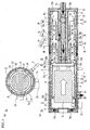
- FIG. 1 shows an engine exhaust gas heat exchanger 1 according to the present invention
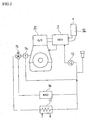
- FIG. 2 shows an example of a coolant circuit diagram of a gas engine 11 provided with the engine exhaust gas heat exchanger 1.
- the engine exhaust gas heat exchanger 1 is configured with unit exhaust gas passages 3a, 3b, 3c, which form three stages, composed of a first exhaust gas passage A and a second exhaust gas passage B provided inside an inner cylindrical pipe 21 of a heat exchanger 2.
- the engine exhaust gas heat exchanger 1 is, as shown in FIGS. 1 and 2 , provided such that exhaust gas from the engine 11 to a silencer 12 travels through a front chamber 5, an engine exhaust gas purification catalyst (hereinafter simply referred to as a catalyst) 4, and the unit exhaust gas passages 3a, 3b, 3c, inside the engine exhaust gas heat exchanger 1 and that the coolant of the engine 11 travels through the heat exchanger 2 of the engine exhaust gas heat exchanger 1 and then enters the engine 11.
- the coolant that has traveled through the engine 11 is configured to be recirculated by a pump 13. Also, the temperature of the coolant can be monitored by a thermostat 14, and the flow of the coolant can be switched toward a radiator 16 or a heat exchanger 17 by a three-way valve 15.
- the heat exchanger 2 is composed of the inner cylindrical pipe 21 and an outer cylindrical pipe 22 as well as inner covers 21a, 21b and outer covers 22a, 22b provided at the respective ends thereof, and the space therebetween is a coolant passage 20 through which the coolant travels.
- the outer cover 22b is provided with a coolant introduction pipe 23 that is in communication with the coolant passage 20 at the second end, and the outer cylindrical pipe 22 is provided with a coolant effluent pipe 24 that is in communication with the coolant passage 20 at the first end. Accordingly, the coolant is introduced into the coolant passage 20 from the coolant introduction pipe 23, travels toward the first end side from the second end side of the heat exchanger 2, and then is discharged through the coolant effluent pipe 24.
- the heat exchanger 2 is provided at the first end with an exhaust gas introduction pipe 25 that penetrates the inner cylindrical pipe 21 and the outer cylindrical pipe 22 and that is in communication with the inside of the inner cylindrical pipe 21, and provided at the second end with an exhaust gas effluent pipe 26 that penetrates the inner cylindrical pipe 21 and the outer cylindrical pipe 22 and that is in communication with the inside of the inner cylindrical pipe 21.
- exhaust gas is configured so as to be introduced into the inner cylindrical pipe 21 through the exhaust gas introduction pipe 25, travels from the front chamber 5 formed in the inner cylindrical pipe 21 through the catalyst 4 and the three-stage unit exhaust gas passages 3a, 3b, 3c, and then is discharged through the exhaust gas effluent pipe 26.
- the front chamber 5 is configured such that a tubular member 51, which is cylindrical and has a slightly smaller diameter than the inner cylindrical pipe 21 and one end of which forms a curved surface and the diameter of which gradually decreases, is provided inside the inner cylindrical pipe 21 so as to form a space S between the inner cylindrical pipe 21 and the tubular member 51.
- the first end that is on the smaller diameter side of the tubular member 51 is fixed to the inner cover 21a provided at the first end of the heat exchanger 2.
- the exhaust gas introduction pipe 25 is in communication with the inside of the tubular member 51.
- the second end of the tubular member 51 is provided with a cylindrical connecting member 52 to receive and be connected with the catalyst 4 and an exhaust gas discharge pipe 31.
- the connecting member 52 is configured such that the diameter of a cylindrical main body 52a part that is in contact with the inner circumferential surface of the inner cylindrical pipe 21 is reduced in a two-step manner so as to form an exhaust gas discharge pipe connecting part 52b and a catalyst connecting part 52c.
- the main body 52a part having the largest diameter is located between the inner cylindrical pipe 21 and the tubular member 51, and is fixed so as to maintain the space S between the inner cylindrical pipe 21 and the tubular member 51.
- the exhaust gas discharge pipe connecting part 52b receives and is connected with the exhaust gas discharge pipe 31 on the outside so as to form a space d between the inner cylindrical pipe 21 and the exhaust gas discharge pipe 31.
- the catalyst connecting part 52c receives and is connected with the catalyst 4 on the inside.
- the unit exhaust gas passage 3a is configured with the exhaust gas discharge pipe 31 that is connected with the exhaust gas discharge pipe connecting part 52b of the connecting member 52 and a connecting member 32 provided on the downstream side of the exhaust gas discharge pipe 31.
- the exhaust gas discharge pipe 31 can form the space d between the inner cylindrical pipe 21 and the exhaust gas discharge pipe 31, and is formed in a cylindrical shape having a diameter and a length that allows the catalyst 4 to be accommodated inside.
- a plurality of apertures 30 are provided at regular intervals in the longitudinal direction and in the circumferential direction.
- the exhaust gas discharge pipe 31 is blocked by a cover 31a at the downstream end.
- the exhaust gas discharge pipe 31 is fixed inside the inner cylindrical pipe 21 by ribs 31b suitably provided in positions that are between the inner circumferential surface of the inner cylindrical pipe 21 and the exhaust gas discharge pipe 31 and that do not interfere with the apertures 30.
- the ribs 31b are also provided on the inner circumferential surface of the exhaust gas discharge pipe 31, thus making it possible to retain the catalyst 4 furnished more toward the center than the exhaust gas discharge pipe 31. While the catalyst 4 is retained, a thermometer 6 is provided between the catalyst 4 and the cover 31a so as to penetrate the outer cylindrical pipe 22 and the inner cylindrical pipe 21 as well as the exhaust gas discharge pipe 31 of the heat exchanger 2. It is desirable to monitor the temperature of the catalyst 4 since the purification effect is not effectively demonstrated depending on the exhaust gas temperature, and measuring the temperature by the thermometer 6 at a position immediately after exhaust gas has traveled through the catalyst 4 makes it possible to grasp, to some extent, the purifying state of the catalyst 4.
- the diameter of the connecting member 32 further decreases, thus forming an exhaust gas discharge pipe connecting part 32b.
- the main body 32a part having the largest diameter is fixed to the inner circumferential surface of the inner cylindrical pipe 21.
- the exhaust gas discharge pipe connecting part 32b receives and is connected with on the outside an exhaust gas discharge pipe 33 that constitutes the unit exhaust gas passage 3b of the next stage so as to form a space d between the inner cylindrical pipe 21 and the exhaust gas discharge pipe 33.
- the unit exhaust gas passage 3a forms the first exhaust gas passage A in which exhaust gas that has traveled through the catalyst is blocked by the cover 31a and discharged through the apertures 30 and the second exhaust gas passage B in which exhaust gas after being discharged through the apertures 30 travels through the space d between the exhaust gas discharge pipe 31 and the inner cylindrical pipe 21 and travels to the next-stage discharge pipe 33 through the discharge pipe connecting part 32b of the connecting member 32.
- the unit exhaust gas passage 3b is configured with the exhaust gas discharge pipe 33 connected to the exhaust gas discharge pipe connecting part 32b of the connecting member 32 and a connecting member 34 provided on the downstream side of the exhaust gas discharge pipe 33.
- the exhaust gas discharge pipe 33 is formed in a cylindrical shape that makes it possible to form the space d between the inner cylindrical pipe 21 and the exhaust gas discharge pipe 33.
- a plurality of apertures 30 are provided at regular intervals in the longitudinal direction and in the circumferential direction.
- the exhaust gas discharge pipe 33 is blocked by a cover 33a at the downstream end.
- the exhaust gas discharge pipe 33 is fixed inside the inner cylindrical pipe 21 by ribs 33b suitably provided in positions on the outer circumferential surface at the downstream end, which are between the inner circumferential surface of the inner cylindrical pipe 21 and the exhaust gas discharge pipe 33 and do not interfere with the apertures 30.
- the diameter of the connecting member 34 further decreases, thus forming an exhaust gas discharge pipe connecting part 34b.
- the main body 34a part having the largest diameter is fixed to the inner circumferential surface of the inner cylindrical pipe 21.
- the exhaust gas discharge pipe connecting part 34b receives and is connected with on the outside an exhaust gas discharge pipe 35 that constitutes the unit exhaust gas passage 3c of the next stage so as to form a space d between the inner cylindrical pipe 21 and the exhaust gas discharge pipe 35.
- the unit exhaust gas passage 3b forms the first exhaust gas passage A in which exhaust gas that has traveled through the discharge pipe connecting part 32b of the connecting member 32 is blocked by the cover 33a and discharged through the apertures 30 and the second exhaust gas passage B in which exhaust gas after being discharged through the apertures 30 travels through the space d between the exhaust gas discharge pipe 33 and the inner cylindrical pipe 21 and travels to the next-stage discharge pipe 35 through the discharge pipe connecting part 34b of the connecting member 34.
- the unit exhaust gas passage 3c is configured with the exhaust gas discharge pipe 35 connected to the exhaust gas discharge pipe connecting part 34b of the connecting member 34 and the exhaust gas effluent pipe 26.
- the exhaust gas discharge pipe 35 is formed in a cylindrical shape that makes it possible to form the space d between the inner cylindrical pipe 21 and the exhaust gas discharge pipe 35.
- a plurality of apertures 30 are provided at regular intervals in the longitudinal direction and in the circumferential direction.
- the length of the exhaust gas discharge pipe 35 is adjusted such that the downstream end is blocked by the inner cover 21b on the second end side of the heat exchanger 2.
- the downstream end of the exhaust gas discharge pipe 35 is fixed to the inner cover 21b on the second end side of the heat exchanger 2.
- the unit exhaust gas passage 3c forms the first exhaust gas passage A in which exhaust gas that has traveled through the discharge pipe connecting part 34b of the connecting member 34 is blocked by the inner cover 21b and discharged through the apertures 30 and the second exhaust gas passage B in which exhaust gas after being discharged through the apertures 30 travels through the space d between the exhaust gas discharge pipe 35 and the inner cylindrical pipe 21 and discharged through the exhaust gas effluent pipe 26.
- exhaust gas from the engine travels through the exhaust gas introduction pipe 25, the exhaust gas front chamber 5, the catalyst 4 and the unit exhaust gas passages 3a, 3b, 3c, and then is discharged through the exhaust gas effluent pipe 26.
- exhaust gas is configured so as not to be discharged at once through all the apertures 30, but is configured so as to be discharged through the apertures 30 of the unit exhaust gas passage 3a and then recovered, discharged through the apertures 30 of the unit exhaust gas passage 3b of the next stage and then recovered again, and discharged through the apertures 30 of the unit exhaust gas passage 3c of the next stage.
- the discharge rate of exhaust gas discharged toward the inner cylindrical pipe 21 of the heat exchanger 2 through the apertures 30 can be maintained at a constant level without being reduced in the unit exhaust gas passages 3a, 3b, 3c. Accordingly, a decrease of the flow rate per aperture 30 is prevented, thus making it possible to maintain a specific average heat transfer coefficient (K value).
- the front chamber 5 forms the space S between the tubular member 51 and the inner cylindrical pipe 21, thus making it possible to prevent exhaust gas that enters through the exhaust gas introduction pipe 25 from being cooled by coolant via the inner cylindrical pipe 21. Accordingly, a temperature decrease of exhaust gas before flowing into the catalyst 4 is prevented, thus making it possible to activate the reaction in the catalyst 4.
- the average heat transfer coefficient (K value) is dependent on the discharge rate of exhaust gas discharged toward the inner cylindrical pipe 21 of the heat exchanger 2 through the apertures 30 (the rate of traveling through the apertures), and the average heat transfer coefficient characteristically is increased as the flow rate is increased.
- the number of the apertures 30 in an upper stage where the temperature of the engine exhaust gas temperature is high is reduced or the diameter of the apertures 30 is made small to increase the flow rate. It is thus possible to increase the average heat transfer coefficient (K value) in a place where the temperature difference between the engine exhaust gas temperature and the coolant temperature is large, thus making it possible to obtain a larger amount of heat exchange than increasing the average heat transfer coefficient (K value) in a lower stage where the temperature difference between the engine exhaust gas temperature and the coolant temperature is small.
- Exhaust gas that has traveled through the apertures 30 of the unit exhaust gas passage 3a of the first stage is heat-exchanged, discharged through the apertures 30 of the unit exhaust gas passage 3b of the second stage and further heat-exchanged therein, and then discharged through the apertures 30 of the unit exhaust gas passage 3c of the third stage. Accordingly, the temperature of exhaust gas is decreased as it travels toward lower stages even if the decrease of the flow rate when exhaust gas is discharged through the apertures 30 is prevented.
- the total areas of the apertures (the number of the apertures 30 x area per aperture) in the respective unit exhaust gas passages are configured to be different for all stages or partially different according to the heat exchangeability required of the engine exhaust gas heat exchanger, thus making it possible to obtain optimal heat exchangeability.
- the engine exhaust gas heat exchanger 1 creates a large temperature difference between the inner cylindrical pipe 21 through which coolant travels and the exhaust gas discharge pipes 31, 33, 35 through which exhaust gas is discharged.
- the inner cylindrical pipe 21 is cooled by the coolant and shrinks and the exhaust gas discharge pipes 31, 33, 35 are heated by the exhaust gas and expand. Therefore, the exhaust gas discharge pipes 31, 33, 35 become elongated relative to the inner cylindrical pipe 21.
- FIG. 1 shows that shows that the exhaust gas discharge pipes 31, 33, 35 become elongated relative to the inner cylindrical pipe 21.
- the connecting member 34 makes it possible to respond to a length change resulting from thermal expansion of the exhaust gas discharge pipe 35.
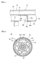
- FIG. 3 shows an engine exhaust gas heat exchanger 1a according to another embodiment of the present invention.
- the members that are identical to those in FIGS. 1 and 2 are given the same references, and descriptions thereof are omitted.
- the engine exhaust gas heat exchanger 1a is configured such that coolant enters inside the second-stage unit exhaust gas passage 3b and the third-stage unit exhaust gas passage 3c, and the second-stage unit exhaust gas passage 3b and the third-stage unit exhaust gas passage 3c are configured so as to undergo heat exchange also with the coolant that has entered inside.
- a shield 36 that separates the first-stage unit exhaust gas passage 3a and the second-stage unit exhaust gas passages 3b is provided in the position of the main body 32a part of the connecting member 32 constituting the first-stage unit exhaust gas passage 3a.
- the coolant introduction pipe 23 is provided so as to extend through the inner cover 21b and the outer cover 22b at the second end of the heat exchanger 2 to reach as far as the shield 36, and openings 23a are provided at the extending end.
- a core pipe 27 Outside the coolant introduction pipe 23 is provided a core pipe 27.
- the core pipe 27 is provided between the inner cover 21b at the second end of the heat exchanger 2 and the shield 36, and is in communication with the coolant passage 20 inside the inner cover 21b. Accordingly, coolant is introduced to the position of the second-stage unit exhaust gas passage 3b where the openings 23a of the coolant introduction pipe 23 are provided, flows into the core pipe 27, flows to the second end of the heat exchanger 2, flows into the coolant passage 20, and then is discharged through the coolant effluent pipe 24.
- the shield 36 is provided with a plurality of exhaust gas passing holes 36a arranged in a circular pattern at positions of a specific radius of curvature.
- an exhaust gas discharge pipe 37 having a dual-pipe structure composed of an inner exhaust gas discharge pipe 37a and an outer exhaust gas discharge pipe 37b is provided, and exhaust gas entering through the exhaust gas passing holes 36a of the shield 36 is introduced between the inner exhaust gas discharge pipe 37a and the outer exhaust gas discharge pipe 37b.
- the exhaust gas discharge pipe 37 is blocked by being provided with a circular cover 37c at the downstream end of the inner exhaust gas discharge pipe 37a and the outer exhaust gas discharge pipe 37b.
- a plurality of apertures 30 are provided at regular intervals in the longitudinal direction and in the circumferential direction.
- the inner exhaust gas discharge pipe 37a is provided with the apertures 30 at a 90 degree pitch in the circumferential direction
- the outer exhaust gas discharge pipe 37b is provided with the apertures 30 at a 45 degree pitch in the circumferential direction.
- the apertures 30 provided in the outer exhaust gas discharge pipe 37b discharge exhaust gas toward the inner circumferential surface of the inner cylindrical pipe 21 that has a large diameter than the outer exhaust gas discharge pipe 37b, while the apertures 30 provided in the inner exhaust gas discharge pipe 37a discharge exhaust gas toward the core pipe 27 that has a smaller diameter than the inner exhaust gas discharge pipe 37a. Therefore, configuring the number of the apertures 30 provided in the outer exhaust gas discharge pipe 37b so as to be larger than the number of the apertures 30 provided in the inner exhaust gas discharge pipe 37a by selecting different pitches for the apertures 30 in the outer exhaust gas discharge pipe 37b and the inner exhaust gas discharge pipe 37a as described above makes it possible to attain a uniform unit heat transfer area per aperture 30.
- the pitch is not particularly limited to 90 degrees or 45 degrees, and is suitably determined according to the size of the inner circumferential surface of the inner cylindrical pipe 21 toward which exhaust gas is discharged from the outer exhaust gas discharge pipe 37b as well as the outer circumferential surface of the core pipe 27 toward which exhaust gas is discharged from the inner exhaust gas discharge pipe 37a.
- a core connecting member 38 In the position of the core pipe 27 corresponding to the position of the connecting member 34 is provided a core connecting member 38.
- the core connecting member 38 is configured so as to form an inner pipe connecting part 38b by further increasing its diameter beyond a cylindrical main body 38a part that can be fixed to the outer circumferential surface of the core pipe 27.
- the exhaust gas discharge pipe connecting part 34b of the connecting member 34 receives and is connected with on the outside an outer exhaust gas discharge pipe 39b that constitutes the unit exhaust gas passage 3c of the next stage.
- the inner pipe connecting part 38b of the core connecting member 38 receives and is connected with on the inside an inner exhaust gas discharge pipe 39a that constitutes the unit exhaust gas passage 3c of the next stage.
- the unit exhaust gas passage 3b of the second stage forms the first exhaust gas passage A in which exhaust gas that has traveled through the exhaust gas passing holes 36a of the shield 36 is blocked by the cover 37c and discharged through the apertures 30 provided in both inner exhaust gas discharge pipe 37a and outer exhaust gas discharge pipe 37b and the second exhaust gas passage B in which exhaust gas after being discharged through the apertures 30 travels through the space d between the outer exhaust gas discharge pipe 37b and the inner cylindrical pipe 21 and the space d between the inner exhaust gas discharge pipe 37a and the core pipe 27 and enters the next-stage exhaust gas discharge pipe 39 through between the discharge pipe connecting part 34b of the connecting member 34 and the inner pipe connecting part 38b of the core pipe connecting member 38.
- the unit exhaust gas passage 3c is configured with the exhaust gas effluent pipe 26 and the exhaust gas discharge pipe 39 connected to the exhaust gas discharge pipe connecting part 34b of the connecting member 34 and the inner pipe connecting part 38b of the core pipe connecting member 38.
- the exhaust gas discharge pipe 39 as with the exhaust gas discharge pipe 37, has a dual-pipe structure composed of the inner exhaust gas discharge pipe 39a and the outer exhaust gas discharge pipe 39b, and is configured so as to allow exhaust gas to be discharged through the apertures 30 provided in the outer exhaust gas discharge pipe 39b and the inner exhaust gas discharge pipe 39a toward the inner cylindrical pipe 21 and the core pipe 27, respectively.
- the apertures 30 in the inner exhaust gas discharge pipe 39a are provided at a 90 degree pitch in the circumferential direction, and the apertures 30 in the outer exhaust gas discharge pipe 39b are provided at a 45 degree pitch in the circumferential direction.
- the downstream end of the inner exhaust gas discharge pipe 39a has an increased diameter to contact and is fixed to the outer exhaust gas discharge pipe 39b.
- the downstream end of the outer exhaust gas discharge pipe 39b is fixed to the inner cover 21b on the second end side of the heat exchanger 2 while being in contact therewith. Also, near the downstream end of the outer exhaust gas discharge pipe 39b, passing holes 39c that allow exhaust gas discharged from the inner exhaust gas discharge pipe 39a to travel through are provided.
- the unit exhaust gas passage 3c of the third stage forms the first exhaust gas passage A in which exhaust gas that has traveled between the inner exhaust gas discharge pipe 39a and the outer exhaust gas discharge pipe 39b through the space between the exhaust gas discharge pipe connecting part 34b of the connecting member 34 and the inner pipe connecting part 38b of the core pipe connecting member 38 is blocked at the downstream end and discharged through the apertures 30 provided in both inner exhaust gas discharge pipe 39a and outer exhaust gas discharge pipe 39b and the second exhaust gas passage B in which exhaust gas after being discharged through the apertures 30 travels through the space d between the outer exhaust gas discharge pipe 39b and the inner cylindrical pipe 21 and the space d between the inner exhaust gas discharge pipe 39a and the core pipe 27 and is discharged through the exhaust gas effluent pipe 26.
- exhaust gas is discharged through the inner exhaust gas discharge pipes 37a, 39a, thus making it possible to exchange heat on the outer circumferential surface of the core pipe 27. Therefore, this makes it possible to secure a large heat transfer area without increasing the overall length and the overall diameter of the exhaust gas heat exchanger 1.
- FIG. 6 shows other embodiments of the apertures 30 in the engine exhaust gas heat exchanger 1 of the present invention.
- the members that are identical to those in FIG. 1 are given the same references, and descriptions thereof are omitted.
- the apertures 30 has such a shape that the area through which exhaust gas travels gradually decreases from the inlet toward the outlet of the apertures 30.
- the apertures may be created in a truncated cone shape with which the diameter gradually decreases over the entire thickness direction of the exhaust gas discharge pipe 31 as shown in FIG. 6(a) , or as shown in FIG. 6(b) , the apertures may be created so as to have a truncated cone shape with which the diameter gradually decreases from the inlet side until the midsection in the thickness direction of the exhaust gas discharge pipe 31 and a cylindrical shape having the same diameter as the outlet from the midsection.
- the apertures 30 provided in the exhaust gas discharge pipes 31, 33, 35 are shaped such that the area through which exhaust gas travels gradually decreases from the inlet toward the outlet, thus making it possible to reduce the exhaust gas pressure loss at the same aperture traveling rate. Accordingly, it is possible to raise the aperture traveling rate relative to the designed allowable pressure loss value of the heat exchanger 2, and it is possible to increase the average heat transfer coefficient and increase the heat exchange amount.
- the exhaust gas discharge rate can be kept constant without a decrease in the unit exhaust gas passages 3a, 3b, 3c, and therefore, the apertures 30 having such a configuration will function effectively.
- the apertures 30 are shaped to have a diameter that gradually decreases from the inside toward the outside of the circumferential wall.
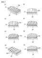
- groove processing may be performed on the inner circumferential surface of the inner cylindrical pipe 21 with which gas discharged through the apertures 30 collides.
- the inner circumferential surface of the inner cylindrical pipe 21 can disrupt the flow of exhaust gas that is blown against the inner circumferential surface, thus making it possible to increase the heat exchange amount.
- projections 21a projecting toward the inner circumferential surface side may be formed in the length direction of the inner cylindrical pipe 21 (see FIG. 7 (a) ), may be formed in the circumferential direction (see to FIG.
- this groove processing may form trough-like grooves 21b so as to have hollows on the inner circumferential surface side of the inner cylindrical pipe 21.
- dimple processing may be performed on the inner circumferential surface of the inner cylindrical pipe 21 against which gas discharged through the apertures 30 hits.
- the shape of dimples may be depressions 21c having circular hollows as provided on a golf ball.
- this dimple processing may form protrusions 21d that have a circular shape protruding toward the inner circumferential surface side of the inner cylindrical pipe 21.
- the engine exhaust gas heat exchanger 1 is configured with three unit exhaust gas passages 3a, 3b, 3c, but the number of passages is not particularly limited to three, and as long as multiple passages are provided, the number thereof may be two or four or more.
- the present invention can be used as an exhaust gas heat exchanger for various engines used in air-conditioners and cogeneration systems.
Landscapes
- Engineering & Computer Science (AREA)
- Mechanical Engineering (AREA)
- General Engineering & Computer Science (AREA)
- Physics & Mathematics (AREA)
- Thermal Sciences (AREA)
- Chemical & Material Sciences (AREA)
- Chemical Kinetics & Catalysis (AREA)
- Combustion & Propulsion (AREA)
- Geometry (AREA)
- Health & Medical Sciences (AREA)
- Toxicology (AREA)
- Exhaust Gas After Treatment (AREA)
- Heat-Exchange Devices With Radiators And Conduit Assemblies (AREA)
- Exhaust Silencers (AREA)
Claims (6)
- Un échangeur de chaleur de gaz d'échappement de moteur (1) qui un échangeur de chaleur entre le gaz d'échappement du moteur et un agent de refroidissement, et dans lequel plusieurs ouvertures (30) faisant face à un passage d'agent de refroidissement (20) sont disposées dans la direction circonférentielle et dans la direction du flux de gaz d'échappement d'un passage d'échappement pour permettre à la quantité totale de gaz d'échappement d'entrer en contact avec l'agent de refroidissement (20), ledit échangeur de chaleur de gaz d'échappement de moteur (1) comprenant un catalyseur pour la purification des gaz d'échappement (4), caractérisé en ce que ledit échangeur de chaleur de gaz d'échappement de moteur (1) comporte de nombreuses étapes d'une unité de passage d'échappement (3a, 3b, 3c) qui est configuré avec un premier passage d'échappement (A) dans lequel un plan tourné vers l'admission est bloqué, et qui a plusieurs ouvertures (30) disposées dans la direction circonférentielle et dans la direction du flux, et avec un second passage d'échappement (B) qui comporte un mur de division faisant face aux ouvertures (30) et servant aussi de passage d'agent de refroidissement (20) et une sortie (36a) qui sert aussi d'admission pour le premier passage d'échappement (A) de l'étape suivante (3b, 3c) ou de sortie pour l'échangeur de chaleur du gaz d'échappement de moteur (26),
et dans lequel la surface totale des ouvertures (30) dans chaque unité de passage d'échappement (3a, 3b, 3c) est différente pour toutes les étapes (3a, 3b, 3c) ou partiellement différente et plus on s'approche de l'étape inférieure, où le différence de température entre la température du gaz d'échappement de moteur et la température de l'agent de refroidissement est plus petite, plus le nombre des ouvertures (30) ou le diamètre des ouvertures (30) est réduit,
et dans lequel ledit catalyseur pour la purification des gaz d'échappement (4) est partiellement ou entièrement logé dans le premier passage d'échappement (A) de l'unité de la première étape du passage d'échappement (3a), et un capteur de température du gaz d'échappement (6) est placé entre le plan de sortie du catalyseur et le plan bloqué (31) du premier passage d'échappement (A). - L' échangeur de chaleur de gaz d'échappement de moteur (1) selon la revendication 1, dans lequel le passage d'agent de refroidissement (20) est placé à la fois sur le côté circonférentiel interne et sur le côté circonférentiel externe du passage d'échappement, et les ouvertures (30) faisant respectivement face aux passages d'agent de refroidissement sont placées dans le premier passage d'échappement (A).
- L'échangeur de chaleur de gaz d'échappement de moteur (1) selon la revendication 2, dans lequel les ouvertures (30) faisant face au passage d'agent de refroidissement sur le côté circonférentiel externe sont présentes en plus grand nombre que les ouvertures (30) faisant face au passage d'agent de refroidissement sur le côté circonférentiel interne.
- L'échangeur de chaleur de gaz d'échappement de moteur (1) selon la revendication 1, dans lequel la surface de chaque ouverture (30) à travers laquelle passe le gaz d'échappement est la même depuis une section intermédiaire jusqu'à la sortie.
- L'échangeur de chaleur de gaz d'échappement de moteur (1) selon la revendication 1, dans lequel un dispositif de rainurage est réalisé sur la surface du passage d'agent de refroidissement (20) en contact avec le gaz d'échappement.
- Un dispositif d'alimentation en énergie, tel qu'une pompe à chaleur entraînée par un moteur et une cogénération dans lequel un échangeur de chaleur de gaz d'échappement de moteur (1) d'une quelconque revendication 1 à 5 est utilisé dans un passage de gaz d'échappement de moteur.
Applications Claiming Priority (3)
| Application Number | Priority Date | Filing Date | Title |
|---|---|---|---|
| JP2010055575A JP2011190708A (ja) | 2010-03-12 | 2010-03-12 | エンジン排気ガス熱交換器およびこれを使用したエネルギー供給装置 |
| JP2010055573A JP5551476B2 (ja) | 2010-03-12 | 2010-03-12 | エンジン排気ガス熱交換器ならびにこれを使用したエネルギー供給装置 |
| PCT/JP2011/055633 WO2011111776A1 (fr) | 2010-03-12 | 2011-03-10 | Échangeur de chaleur de gaz d'échappement de moteur et dispositif d'alimentation en énergie l'utilisant |
Publications (3)
| Publication Number | Publication Date |
|---|---|
| EP2546491A1 EP2546491A1 (fr) | 2013-01-16 |
| EP2546491A4 EP2546491A4 (fr) | 2013-10-02 |
| EP2546491B1 true EP2546491B1 (fr) | 2016-03-09 |
Family
ID=44563574
Family Applications (1)
| Application Number | Title | Priority Date | Filing Date |
|---|---|---|---|
| EP11753434.7A Not-in-force EP2546491B1 (fr) | 2010-03-12 | 2011-03-10 | Échangeur de chaleur de gaz d'échappement de moteur et dispositif d'alimentation en énergie utilisant celui-ci |
Country Status (5)
| Country | Link |
|---|---|
| US (1) | US8904772B2 (fr) |
| EP (1) | EP2546491B1 (fr) |
| CA (1) | CA2792916A1 (fr) |
| ES (1) | ES2575583T3 (fr) |
| WO (1) | WO2011111776A1 (fr) |
Families Citing this family (6)
| Publication number | Priority date | Publication date | Assignee | Title |
|---|---|---|---|---|
| EP2746549B1 (fr) * | 2012-12-21 | 2017-09-27 | EC Power A/S | Appareil convertisseur catalytique |
| JP6251583B2 (ja) * | 2014-01-30 | 2017-12-20 | カルソニックカンセイ株式会社 | 排気熱回収器 |
| KR101724909B1 (ko) * | 2015-09-23 | 2017-04-07 | 현대자동차주식회사 | 자동차용 배기열 회수 및 egr 제어 시스템 |
| JP7169923B2 (ja) * | 2019-03-27 | 2022-11-11 | 日本碍子株式会社 | 熱交換器 |
| CN111750705B (zh) * | 2019-03-28 | 2022-04-29 | 日本碍子株式会社 | 热交换器的流路结构以及热交换器 |
| CN113250795B (zh) * | 2021-06-28 | 2021-11-26 | 宁波明讯实业有限公司 | 一种环保型汽车尾气处理系统及处理办法 |
Citations (3)
| Publication number | Priority date | Publication date | Assignee | Title |
|---|---|---|---|---|
| US3117559A (en) * | 1960-09-21 | 1964-01-14 | Fives Penhoet | Heat exchanger |
| US4694894A (en) * | 1984-09-14 | 1987-09-22 | Aisin Seiki Kabushiki Kaisha | Heat exchangers |
| US5468384A (en) * | 1992-10-20 | 1995-11-21 | Societe Anonyme Dite Societe Des Ceramiques Techniques | Module for filtering, separating, purifying gases or liquids, or for catalytic conversion |
Family Cites Families (16)
| Publication number | Priority date | Publication date | Assignee | Title |
|---|---|---|---|---|
| US3844343A (en) | 1973-02-02 | 1974-10-29 | Gen Electric | Impingement-convective cooling system |
| JPS6078920U (ja) * | 1983-11-05 | 1985-06-01 | 株式会社土屋製作所 | 廃熱回収式触媒コンバ−タ |
| US4685292A (en) * | 1985-09-09 | 1987-08-11 | Zwick Energy Research Organization, Inc. | Exhaust cooling system for internal combustion engine |
| FR2619205B1 (fr) | 1987-08-07 | 1990-08-31 | Bertin & Cie | Echangeur de chaleur a impact de jet |
| JPH01145931U (fr) | 1988-03-31 | 1989-10-06 | ||
| US5228513A (en) | 1991-05-03 | 1993-07-20 | Indugas, Inc. | Convective heat transfer by cascading jet impingement |
| US6151891A (en) * | 1998-09-22 | 2000-11-28 | Bennett; Easton | Heat exchanger for a motor vehicle exhaust |
| DE60113646T2 (de) * | 2000-01-21 | 2006-03-16 | Honda Giken Kogyo K.K. | Abgasreinigungsvorrichtung und brennkraftmaschine |
| DE10247837A1 (de) * | 2002-10-14 | 2004-04-22 | Behr Gmbh & Co. | Wärmeübertrager |
| JP2008035595A (ja) | 2006-07-27 | 2008-02-14 | Toyota Motor Corp | 熱発電装置及びその製造方法 |
| JP4281789B2 (ja) * | 2006-12-06 | 2009-06-17 | トヨタ自動車株式会社 | 排気熱回収装置 |
| JP2008175461A (ja) | 2007-01-18 | 2008-07-31 | Toyota Motor Corp | 熱交換器 |
| WO2009048090A1 (fr) | 2007-10-10 | 2009-04-16 | Yanmar Co., Ltd. | Dispositif de récupération de chaleur d'échappement de moteur et dispositif d'alimentation en énergie l'utilisant |
| JP4324216B2 (ja) * | 2007-10-10 | 2009-09-02 | ヤンマー株式会社 | エンジン排気ガス熱回収器ならびにそれを使用したエンジン駆動式ヒートポンプまたはコージェネレーション |
| JP4324219B2 (ja) * | 2007-12-26 | 2009-09-02 | ヤンマー株式会社 | エンジン排気ガス熱回収器ならびにこれを使用したエネルギー供給装置 |
| KR101125004B1 (ko) * | 2009-12-04 | 2012-03-27 | 기아자동차주식회사 | 냉각수 및 오일 통합 열교환형 배기열 회수장치 |
-
2011
- 2011-03-10 EP EP11753434.7A patent/EP2546491B1/fr not_active Not-in-force
- 2011-03-10 WO PCT/JP2011/055633 patent/WO2011111776A1/fr not_active Ceased
- 2011-03-10 ES ES11753434.7T patent/ES2575583T3/es active Active
- 2011-03-10 CA CA2792916A patent/CA2792916A1/fr not_active Abandoned
- 2011-03-10 US US13/583,774 patent/US8904772B2/en not_active Expired - Fee Related
Patent Citations (3)
| Publication number | Priority date | Publication date | Assignee | Title |
|---|---|---|---|---|
| US3117559A (en) * | 1960-09-21 | 1964-01-14 | Fives Penhoet | Heat exchanger |
| US4694894A (en) * | 1984-09-14 | 1987-09-22 | Aisin Seiki Kabushiki Kaisha | Heat exchangers |
| US5468384A (en) * | 1992-10-20 | 1995-11-21 | Societe Anonyme Dite Societe Des Ceramiques Techniques | Module for filtering, separating, purifying gases or liquids, or for catalytic conversion |
Also Published As
| Publication number | Publication date |
|---|---|
| ES2575583T3 (es) | 2016-06-29 |
| WO2011111776A1 (fr) | 2011-09-15 |
| US20130000286A1 (en) | 2013-01-03 |
| US8904772B2 (en) | 2014-12-09 |
| CA2792916A1 (fr) | 2011-09-15 |
| EP2546491A1 (fr) | 2013-01-16 |
| EP2546491A4 (fr) | 2013-10-02 |
Similar Documents
| Publication | Publication Date | Title |
|---|---|---|
| CN101809260B (zh) | 发动机排气气体热回收器以及使用它的能量供给装置 | |
| JP2010133428A (ja) | 排気ガス熱交換器 | |
| EP1957784B1 (fr) | Echangeur de chaleur a trois passes pour systeme de recirculation de gaz d'echappement | |
| US8904772B2 (en) | Engine exhaust gas heat exchanger and energy supplying device using the same | |
| JP2017032271A (ja) | 螺旋状通路を備えた向流式熱交換器 | |
| JP5967300B2 (ja) | 熱交換器 | |
| JP2005036739A (ja) | Egrクーラ | |
| JP4810511B2 (ja) | 内燃機関の排熱回収装置 | |
| CN105972617B (zh) | 热力后燃烧装置 | |
| JP4324219B2 (ja) | エンジン排気ガス熱回収器ならびにこれを使用したエネルギー供給装置 | |
| JP3783395B2 (ja) | Egrクーラ | |
| FI130318B (en) | Tube bundle heat exchanger | |
| JP2007315370A (ja) | 排気熱回収排気浄化装置 | |
| US20050103484A1 (en) | Heat exchanger | |
| KR102956223B1 (ko) | 역류 유체를 가이드하기 위한 복열 장치를 갖는 복열 장치 버너 | |
| KR101611096B1 (ko) | 배기가스 열교환기 | |
| FI117853B (fi) | Katalysaattoriyksikkö ja -järjestely | |
| CN111164356A (zh) | 壳管式热交换器 | |
| JP7311655B2 (ja) | 熱交換器 | |
| JP7511686B2 (ja) | 熱交換器 | |
| JP5551476B2 (ja) | エンジン排気ガス熱交換器ならびにこれを使用したエネルギー供給装置 | |
| CN222418682U (zh) | 换热器 | |
| JP2007085331A (ja) | 排気還流ガス冷却装置 | |
| JPH08247684A (ja) | 熱交換器 | |
| JP2025086168A (ja) | 熱交換器 |
Legal Events
| Date | Code | Title | Description |
|---|---|---|---|
| PUAI | Public reference made under article 153(3) epc to a published international application that has entered the european phase |
Free format text: ORIGINAL CODE: 0009012 |
|
| 17P | Request for examination filed |
Effective date: 20120917 |
|
| AK | Designated contracting states |
Kind code of ref document: A1 Designated state(s): AL AT BE BG CH CY CZ DE DK EE ES FI FR GB GR HR HU IE IS IT LI LT LU LV MC MK MT NL NO PL PT RO RS SE SI SK SM TR |
|
| DAX | Request for extension of the european patent (deleted) | ||
| A4 | Supplementary search report drawn up and despatched |
Effective date: 20130904 |
|
| RIC1 | Information provided on ipc code assigned before grant |
Ipc: B01D 53/86 20060101ALI20130829BHEP Ipc: F01N 5/02 20060101AFI20130829BHEP |
|
| 17Q | First examination report despatched |
Effective date: 20140527 |
|
| RIC1 | Information provided on ipc code assigned before grant |
Ipc: F28F 13/06 20060101ALI20150907BHEP Ipc: F01N 5/02 20060101AFI20150907BHEP Ipc: F28D 7/10 20060101ALI20150907BHEP Ipc: F01N 3/28 20060101ALI20150907BHEP |
|
| GRAP | Despatch of communication of intention to grant a patent |
Free format text: ORIGINAL CODE: EPIDOSNIGR1 |
|
| INTG | Intention to grant announced |
Effective date: 20151026 |
|
| GRAS | Grant fee paid |
Free format text: ORIGINAL CODE: EPIDOSNIGR3 |
|
| GRAA | (expected) grant |
Free format text: ORIGINAL CODE: 0009210 |
|
| RAP1 | Party data changed (applicant data changed or rights of an application transferred) |
Owner name: YANMAR CO., LTD. |
|
| RIN1 | Information on inventor provided before grant (corrected) |
Inventor name: MATSUURA, KOSUKE Inventor name: AZUMA, HIROSHI |
|
| AK | Designated contracting states |
Kind code of ref document: B1 Designated state(s): AL AT BE BG CH CY CZ DE DK EE ES FI FR GB GR HR HU IE IS IT LI LT LU LV MC MK MT NL NO PL PT RO RS SE SI SK SM TR |
|
| REG | Reference to a national code |
Ref country code: GB Ref legal event code: FG4D |
|
| REG | Reference to a national code |
Ref country code: AT Ref legal event code: REF Ref document number: 779706 Country of ref document: AT Kind code of ref document: T Effective date: 20160315 Ref country code: CH Ref legal event code: EP |
|
| REG | Reference to a national code |
Ref country code: FR Ref legal event code: PLFP Year of fee payment: 6 |
|
| REG | Reference to a national code |
Ref country code: IE Ref legal event code: FG4D |
|
| REG | Reference to a national code |
Ref country code: DE Ref legal event code: R096 Ref document number: 602011023855 Country of ref document: DE |
|
| REG | Reference to a national code |
Ref country code: NL Ref legal event code: FP |
|
| REG | Reference to a national code |
Ref country code: ES Ref legal event code: FG2A Ref document number: 2575583 Country of ref document: ES Kind code of ref document: T3 Effective date: 20160629 |
|
| REG | Reference to a national code |
Ref country code: LT Ref legal event code: MG4D |
|
| PG25 | Lapsed in a contracting state [announced via postgrant information from national office to epo] |
Ref country code: FI Free format text: LAPSE BECAUSE OF FAILURE TO SUBMIT A TRANSLATION OF THE DESCRIPTION OR TO PAY THE FEE WITHIN THE PRESCRIBED TIME-LIMIT Effective date: 20160309 Ref country code: GR Free format text: LAPSE BECAUSE OF FAILURE TO SUBMIT A TRANSLATION OF THE DESCRIPTION OR TO PAY THE FEE WITHIN THE PRESCRIBED TIME-LIMIT Effective date: 20160610 Ref country code: HR Free format text: LAPSE BECAUSE OF FAILURE TO SUBMIT A TRANSLATION OF THE DESCRIPTION OR TO PAY THE FEE WITHIN THE PRESCRIBED TIME-LIMIT Effective date: 20160309 Ref country code: NO Free format text: LAPSE BECAUSE OF FAILURE TO SUBMIT A TRANSLATION OF THE DESCRIPTION OR TO PAY THE FEE WITHIN THE PRESCRIBED TIME-LIMIT Effective date: 20160609 |
|
| REG | Reference to a national code |
Ref country code: AT Ref legal event code: MK05 Ref document number: 779706 Country of ref document: AT Kind code of ref document: T Effective date: 20160309 |
|
| PG25 | Lapsed in a contracting state [announced via postgrant information from national office to epo] |
Ref country code: RS Free format text: LAPSE BECAUSE OF FAILURE TO SUBMIT A TRANSLATION OF THE DESCRIPTION OR TO PAY THE FEE WITHIN THE PRESCRIBED TIME-LIMIT Effective date: 20160309 Ref country code: SE Free format text: LAPSE BECAUSE OF FAILURE TO SUBMIT A TRANSLATION OF THE DESCRIPTION OR TO PAY THE FEE WITHIN THE PRESCRIBED TIME-LIMIT Effective date: 20160309 Ref country code: LT Free format text: LAPSE BECAUSE OF FAILURE TO SUBMIT A TRANSLATION OF THE DESCRIPTION OR TO PAY THE FEE WITHIN THE PRESCRIBED TIME-LIMIT Effective date: 20160309 Ref country code: LV Free format text: LAPSE BECAUSE OF FAILURE TO SUBMIT A TRANSLATION OF THE DESCRIPTION OR TO PAY THE FEE WITHIN THE PRESCRIBED TIME-LIMIT Effective date: 20160309 Ref country code: BE Free format text: LAPSE BECAUSE OF NON-PAYMENT OF DUE FEES Effective date: 20160331 Ref country code: PL Free format text: LAPSE BECAUSE OF FAILURE TO SUBMIT A TRANSLATION OF THE DESCRIPTION OR TO PAY THE FEE WITHIN THE PRESCRIBED TIME-LIMIT Effective date: 20160309 |
|
| PG25 | Lapsed in a contracting state [announced via postgrant information from national office to epo] |
Ref country code: EE Free format text: LAPSE BECAUSE OF FAILURE TO SUBMIT A TRANSLATION OF THE DESCRIPTION OR TO PAY THE FEE WITHIN THE PRESCRIBED TIME-LIMIT Effective date: 20160309 Ref country code: IS Free format text: LAPSE BECAUSE OF FAILURE TO SUBMIT A TRANSLATION OF THE DESCRIPTION OR TO PAY THE FEE WITHIN THE PRESCRIBED TIME-LIMIT Effective date: 20160709 |
|
| REG | Reference to a national code |
Ref country code: CH Ref legal event code: PL |
|
| PG25 | Lapsed in a contracting state [announced via postgrant information from national office to epo] |
Ref country code: RO Free format text: LAPSE BECAUSE OF FAILURE TO SUBMIT A TRANSLATION OF THE DESCRIPTION OR TO PAY THE FEE WITHIN THE PRESCRIBED TIME-LIMIT Effective date: 20160309 Ref country code: SK Free format text: LAPSE BECAUSE OF FAILURE TO SUBMIT A TRANSLATION OF THE DESCRIPTION OR TO PAY THE FEE WITHIN THE PRESCRIBED TIME-LIMIT Effective date: 20160309 Ref country code: CZ Free format text: LAPSE BECAUSE OF FAILURE TO SUBMIT A TRANSLATION OF THE DESCRIPTION OR TO PAY THE FEE WITHIN THE PRESCRIBED TIME-LIMIT Effective date: 20160309 Ref country code: SM Free format text: LAPSE BECAUSE OF FAILURE TO SUBMIT A TRANSLATION OF THE DESCRIPTION OR TO PAY THE FEE WITHIN THE PRESCRIBED TIME-LIMIT Effective date: 20160309 Ref country code: PT Free format text: LAPSE BECAUSE OF FAILURE TO SUBMIT A TRANSLATION OF THE DESCRIPTION OR TO PAY THE FEE WITHIN THE PRESCRIBED TIME-LIMIT Effective date: 20160711 Ref country code: AT Free format text: LAPSE BECAUSE OF FAILURE TO SUBMIT A TRANSLATION OF THE DESCRIPTION OR TO PAY THE FEE WITHIN THE PRESCRIBED TIME-LIMIT Effective date: 20160309 |
|
| REG | Reference to a national code |
Ref country code: DE Ref legal event code: R097 Ref document number: 602011023855 Country of ref document: DE |
|
| REG | Reference to a national code |
Ref country code: IE Ref legal event code: MM4A |
|
| PG25 | Lapsed in a contracting state [announced via postgrant information from national office to epo] |
Ref country code: BE Free format text: LAPSE BECAUSE OF FAILURE TO SUBMIT A TRANSLATION OF THE DESCRIPTION OR TO PAY THE FEE WITHIN THE PRESCRIBED TIME-LIMIT Effective date: 20160309 |
|
| PLBE | No opposition filed within time limit |
Free format text: ORIGINAL CODE: 0009261 |
|
| STAA | Information on the status of an ep patent application or granted ep patent |
Free format text: STATUS: NO OPPOSITION FILED WITHIN TIME LIMIT |
|
| PG25 | Lapsed in a contracting state [announced via postgrant information from national office to epo] |
Ref country code: LI Free format text: LAPSE BECAUSE OF NON-PAYMENT OF DUE FEES Effective date: 20160331 Ref country code: DK Free format text: LAPSE BECAUSE OF FAILURE TO SUBMIT A TRANSLATION OF THE DESCRIPTION OR TO PAY THE FEE WITHIN THE PRESCRIBED TIME-LIMIT Effective date: 20160309 Ref country code: IE Free format text: LAPSE BECAUSE OF NON-PAYMENT OF DUE FEES Effective date: 20160310 Ref country code: CH Free format text: LAPSE BECAUSE OF NON-PAYMENT OF DUE FEES Effective date: 20160331 |
|
| 26N | No opposition filed |
Effective date: 20161212 |
|
| PG25 | Lapsed in a contracting state [announced via postgrant information from national office to epo] |
Ref country code: BG Free format text: LAPSE BECAUSE OF FAILURE TO SUBMIT A TRANSLATION OF THE DESCRIPTION OR TO PAY THE FEE WITHIN THE PRESCRIBED TIME-LIMIT Effective date: 20160609 |
|
| REG | Reference to a national code |
Ref country code: FR Ref legal event code: PLFP Year of fee payment: 7 |
|
| PGFP | Annual fee paid to national office [announced via postgrant information from national office to epo] |
Ref country code: NL Payment date: 20170308 Year of fee payment: 7 Ref country code: FR Payment date: 20170307 Year of fee payment: 7 |
|
| PG25 | Lapsed in a contracting state [announced via postgrant information from national office to epo] |
Ref country code: SI Free format text: LAPSE BECAUSE OF FAILURE TO SUBMIT A TRANSLATION OF THE DESCRIPTION OR TO PAY THE FEE WITHIN THE PRESCRIBED TIME-LIMIT Effective date: 20160309 |
|
| PGFP | Annual fee paid to national office [announced via postgrant information from national office to epo] |
Ref country code: GB Payment date: 20170307 Year of fee payment: 7 |
|
| PGFP | Annual fee paid to national office [announced via postgrant information from national office to epo] |
Ref country code: ES Payment date: 20170315 Year of fee payment: 7 Ref country code: IT Payment date: 20170307 Year of fee payment: 7 |
|
| PGFP | Annual fee paid to national office [announced via postgrant information from national office to epo] |
Ref country code: DE Payment date: 20170331 Year of fee payment: 7 |
|
| PG25 | Lapsed in a contracting state [announced via postgrant information from national office to epo] |
Ref country code: MT Free format text: LAPSE BECAUSE OF FAILURE TO SUBMIT A TRANSLATION OF THE DESCRIPTION OR TO PAY THE FEE WITHIN THE PRESCRIBED TIME-LIMIT Effective date: 20160309 |
|
| PG25 | Lapsed in a contracting state [announced via postgrant information from national office to epo] |
Ref country code: HU Free format text: LAPSE BECAUSE OF FAILURE TO SUBMIT A TRANSLATION OF THE DESCRIPTION OR TO PAY THE FEE WITHIN THE PRESCRIBED TIME-LIMIT; INVALID AB INITIO Effective date: 20110310 Ref country code: CY Free format text: LAPSE BECAUSE OF FAILURE TO SUBMIT A TRANSLATION OF THE DESCRIPTION OR TO PAY THE FEE WITHIN THE PRESCRIBED TIME-LIMIT Effective date: 20160309 |
|
| PG25 | Lapsed in a contracting state [announced via postgrant information from national office to epo] |
Ref country code: LU Free format text: LAPSE BECAUSE OF NON-PAYMENT OF DUE FEES Effective date: 20160310 Ref country code: TR Free format text: LAPSE BECAUSE OF FAILURE TO SUBMIT A TRANSLATION OF THE DESCRIPTION OR TO PAY THE FEE WITHIN THE PRESCRIBED TIME-LIMIT Effective date: 20160309 Ref country code: MC Free format text: LAPSE BECAUSE OF FAILURE TO SUBMIT A TRANSLATION OF THE DESCRIPTION OR TO PAY THE FEE WITHIN THE PRESCRIBED TIME-LIMIT Effective date: 20160309 Ref country code: MK Free format text: LAPSE BECAUSE OF FAILURE TO SUBMIT A TRANSLATION OF THE DESCRIPTION OR TO PAY THE FEE WITHIN THE PRESCRIBED TIME-LIMIT Effective date: 20160309 Ref country code: MT Free format text: LAPSE BECAUSE OF FAILURE TO SUBMIT A TRANSLATION OF THE DESCRIPTION OR TO PAY THE FEE WITHIN THE PRESCRIBED TIME-LIMIT Effective date: 20160331 |
|
| REG | Reference to a national code |
Ref country code: DE Ref legal event code: R119 Ref document number: 602011023855 Country of ref document: DE |
|
| PG25 | Lapsed in a contracting state [announced via postgrant information from national office to epo] |
Ref country code: AL Free format text: LAPSE BECAUSE OF FAILURE TO SUBMIT A TRANSLATION OF THE DESCRIPTION OR TO PAY THE FEE WITHIN THE PRESCRIBED TIME-LIMIT Effective date: 20160309 |
|
| REG | Reference to a national code |
Ref country code: NL Ref legal event code: MM Effective date: 20180401 |
|
| GBPC | Gb: european patent ceased through non-payment of renewal fee |
Effective date: 20180310 |
|
| PG25 | Lapsed in a contracting state [announced via postgrant information from national office to epo] |
Ref country code: NL Free format text: LAPSE BECAUSE OF NON-PAYMENT OF DUE FEES Effective date: 20180401 |
|
| PG25 | Lapsed in a contracting state [announced via postgrant information from national office to epo] |
Ref country code: DE Free format text: LAPSE BECAUSE OF NON-PAYMENT OF DUE FEES Effective date: 20181002 |
|
| PG25 | Lapsed in a contracting state [announced via postgrant information from national office to epo] |
Ref country code: IT Free format text: LAPSE BECAUSE OF NON-PAYMENT OF DUE FEES Effective date: 20180310 Ref country code: GB Free format text: LAPSE BECAUSE OF NON-PAYMENT OF DUE FEES Effective date: 20180310 |
|
| PG25 | Lapsed in a contracting state [announced via postgrant information from national office to epo] |
Ref country code: FR Free format text: LAPSE BECAUSE OF NON-PAYMENT OF DUE FEES Effective date: 20180331 |
|
| REG | Reference to a national code |
Ref country code: ES Ref legal event code: FD2A Effective date: 20190903 |
|
| PG25 | Lapsed in a contracting state [announced via postgrant information from national office to epo] |
Ref country code: ES Free format text: LAPSE BECAUSE OF NON-PAYMENT OF DUE FEES Effective date: 20180311 |