EP2546505B1 - Tuyère d'échappement de moteur à turbine à gaz et moteur à turbine à gaz associé - Google Patents
Tuyère d'échappement de moteur à turbine à gaz et moteur à turbine à gaz associé Download PDFInfo
- Publication number
- EP2546505B1 EP2546505B1 EP12174092.2A EP12174092A EP2546505B1 EP 2546505 B1 EP2546505 B1 EP 2546505B1 EP 12174092 A EP12174092 A EP 12174092A EP 2546505 B1 EP2546505 B1 EP 2546505B1
- Authority
- EP
- European Patent Office
- Prior art keywords
- flow control
- nozzle
- slats
- movable
- gas turbine
- Prior art date
- Legal status (The legal status is an assumption and is not a legal conclusion. Google has not performed a legal analysis and makes no representation as to the accuracy of the status listed.)
- Active
Links
- 230000007246 mechanism Effects 0.000 claims description 11
- 238000007789 sealing Methods 0.000 claims description 11
- 238000011144 upstream manufacturing Methods 0.000 description 8
- 230000003014 reinforcing effect Effects 0.000 description 5
- 238000002485 combustion reaction Methods 0.000 description 4
- 238000001816 cooling Methods 0.000 description 4
- 239000000446 fuel Substances 0.000 description 4
- 239000012781 shape memory material Substances 0.000 description 4
- 229910001285 shape-memory alloy Inorganic materials 0.000 description 4
- 238000005728 strengthening Methods 0.000 description 4
- 238000010438 heat treatment Methods 0.000 description 3
- 230000001141 propulsive effect Effects 0.000 description 3
- 230000007423 decrease Effects 0.000 description 2
- 238000006073 displacement reaction Methods 0.000 description 2
- 239000000463 material Substances 0.000 description 2
- 230000002093 peripheral effect Effects 0.000 description 2
- 230000002411 adverse Effects 0.000 description 1
- 230000009286 beneficial effect Effects 0.000 description 1
- 230000003247 decreasing effect Effects 0.000 description 1
- 230000000694 effects Effects 0.000 description 1
- 239000012530 fluid Substances 0.000 description 1
- 230000004048 modification Effects 0.000 description 1
- 238000012986 modification Methods 0.000 description 1
- 230000036961 partial effect Effects 0.000 description 1
- 238000005192 partition Methods 0.000 description 1
- 239000011295 pitch Substances 0.000 description 1
- 230000002829 reductive effect Effects 0.000 description 1
- 238000000926 separation method Methods 0.000 description 1
- 230000003068 static effect Effects 0.000 description 1
- 230000007704 transition Effects 0.000 description 1
Images



Classifications
-
- F—MECHANICAL ENGINEERING; LIGHTING; HEATING; WEAPONS; BLASTING
- F02—COMBUSTION ENGINES; HOT-GAS OR COMBUSTION-PRODUCT ENGINE PLANTS
- F02K—JET-PROPULSION PLANTS
- F02K1/00—Plants characterised by the form or arrangement of the jet pipe or nozzle; Jet pipes or nozzles peculiar thereto
- F02K1/46—Nozzles having means for adding air to the jet or for augmenting the mixing region between the jet and the ambient air, e.g. for silencing
-
- F—MECHANICAL ENGINEERING; LIGHTING; HEATING; WEAPONS; BLASTING
- F02—COMBUSTION ENGINES; HOT-GAS OR COMBUSTION-PRODUCT ENGINE PLANTS
- F02K—JET-PROPULSION PLANTS
- F02K1/00—Plants characterised by the form or arrangement of the jet pipe or nozzle; Jet pipes or nozzles peculiar thereto
- F02K1/002—Plants characterised by the form or arrangement of the jet pipe or nozzle; Jet pipes or nozzles peculiar thereto with means to modify the direction of thrust vector
- F02K1/006—Plants characterised by the form or arrangement of the jet pipe or nozzle; Jet pipes or nozzles peculiar thereto with means to modify the direction of thrust vector within one plane only
-
- F—MECHANICAL ENGINEERING; LIGHTING; HEATING; WEAPONS; BLASTING
- F02—COMBUSTION ENGINES; HOT-GAS OR COMBUSTION-PRODUCT ENGINE PLANTS
- F02K—JET-PROPULSION PLANTS
- F02K1/00—Plants characterised by the form or arrangement of the jet pipe or nozzle; Jet pipes or nozzles peculiar thereto
- F02K1/06—Varying effective area of jet pipe or nozzle
- F02K1/12—Varying effective area of jet pipe or nozzle by means of pivoted flaps
- F02K1/1207—Varying effective area of jet pipe or nozzle by means of pivoted flaps of one series of flaps hinged at their upstream ends on a fixed structure
-
- F—MECHANICAL ENGINEERING; LIGHTING; HEATING; WEAPONS; BLASTING
- F02—COMBUSTION ENGINES; HOT-GAS OR COMBUSTION-PRODUCT ENGINE PLANTS
- F02K—JET-PROPULSION PLANTS
- F02K1/00—Plants characterised by the form or arrangement of the jet pipe or nozzle; Jet pipes or nozzles peculiar thereto
- F02K1/38—Introducing air inside the jet
- F02K1/386—Introducing air inside the jet mixing devices in the jet pipe, e.g. for mixing primary and secondary flow
-
- F—MECHANICAL ENGINEERING; LIGHTING; HEATING; WEAPONS; BLASTING
- F02—COMBUSTION ENGINES; HOT-GAS OR COMBUSTION-PRODUCT ENGINE PLANTS
- F02K—JET-PROPULSION PLANTS
- F02K1/00—Plants characterised by the form or arrangement of the jet pipe or nozzle; Jet pipes or nozzles peculiar thereto
- F02K1/78—Other construction of jet pipes
- F02K1/80—Couplings or connections
- F02K1/805—Sealing devices therefor, e.g. for movable parts of jet pipes or nozzle flaps
-
- F—MECHANICAL ENGINEERING; LIGHTING; HEATING; WEAPONS; BLASTING
- F05—INDEXING SCHEMES RELATING TO ENGINES OR PUMPS IN VARIOUS SUBCLASSES OF CLASSES F01-F04
- F05D—INDEXING SCHEME FOR ASPECTS RELATING TO NON-POSITIVE-DISPLACEMENT MACHINES OR ENGINES, GAS-TURBINES OR JET-PROPULSION PLANTS
- F05D2300/00—Materials; Properties thereof
- F05D2300/50—Intrinsic material properties or characteristics
- F05D2300/505—Shape memory behaviour
Definitions
- This invention relates to a gas turbine engine exhaust nozzle, and in particular to a variable area exhaust nozzle.
- Gas turbine engines are widely used to power aircraft. As is well known, the engine basically provides propulsive power by generating a high velocity stream of gas which is exhausted rearwards through an exhaust nozzle. A single high velocity gas stream is produced by a turbo jet gas turbine engine. More commonly nowadays, however, two streams, a core exhaust and a bypass exhaust, are generated by a ducted fan gas turbine engine or bypass gas turbine engine.
- the optimum area of the nozzle exit of a gas turbine engine exhaust nozzle depends on a variety of factors, such as the ambient conditions of temperature and pressure, and the mass flow of exhaust gas, which depends on the operating condition of the engine. Aircraft engines spend a substantial proportion of their life at cruise, and consequently nozzle exit areas are normally optimised for cruise conditions. Over the operating cycle of the engine, this provides the optimum overall performance and fuel efficiency. However, on takeoff, when the power requirement of the engine is greater than at cruise, the optimum nozzle exit area is greater than it is at cruise, and decreases during climb. Variable area nozzles have been proposed in order to modulate the nozzle exit area during takeoff and climb.
- variable area nozzle comprises a series of tabs at the nozzle exit, alternative ones of which are displaceable radially outwardly relative to fixed tabs in order to provide an increase in the nozzle exit area.
- US 4,422,524 A discloses an aircraft jet engine variable shape, fluid flow nozzle which is adjustable to sound-suppression (take-off) and nozzle open (cruise) modes.
- take-off or sound-suppression mode a plurality of movable flaps are positioned inwardly by actuators so as to form a fluted arrangement with a plurality of webs that define the periphery of the nozzle exit.
- GB 2 153 454 A discloses a seal to reduce a gas stream in space between two mobile elements in relation to one another.
- GB 913 057 A discloses a jet propulsion nozzle in which a tubular wall member defines a gas passage having an outlet at one end and having at least one flap member which is adjustable by mechanical linkage between a first position in which it projects into the gas stream upstream of the outlet to define a first effective area of the nozzle less than the area of the outlet of the tubular member and a second position in which it is retracted and the nozzle has a second effective area greater than the first, the total peripheral extent of the flap members being a minor proportion of the total peripheral extent of the nozzle outlet and structure associated with the flap member or members restricts a substantial flow of gas round their sides.
- GB 877 010 A discloses a variable area propulsion nozzle comprising a number of bent flaps pivoted to the jet pipe at their upstream ends and movable between flat lateral guiding partitions, and controlled by a regulator.
- GB 849 502 A discloses a jet propulsion nozzle comprising a series of flaps pivoted at their upstream ends to swing towards and away from the nozzle axis and cooperate with a stationary structure, adjacent flaps being adapted to swing in opposite senses to define in a first angular setting of the flaps a silenced nozzle having a corrugated contour or having a series of angularly spaced outlet apertures and to define in a second setting of the flaps a substantially frusto-conical nozzle or a nozzle having a corrugated contour whereof the radical depth of the corrugations is small compared with the depth in the first setting.
- GB 1 368 649 A discloses a variable area propulsion nozzle for a gas turbine jet engine comprising a plurality of flaps pivotally mounted at to a support structure and to means for preventing leakage between the edges of adjacent flaps and between the flaps and the support structure.
- the flaps When applied to the fan propulsion nozzle of a gas turbine ducted fan engine, the flaps are pivotally mounted at the downstream end of the fan casing, the flaps being moved pivotally by means of actuators.
- a seal member comprising a circumferential band formed with a flexible fold is secured to the fan casing and to the forward edges of the flaps to prevent leakage therebetween.
- GB 2 374 121 A discloses a gas turbine engine exhaust nozzle comprising a plurality of tabs which extend in a generally axial direction from a downstream portion of the nozzle, and an actuation mechanism capable of moving the tabs between a first deployed position, where the tabs interact with a gas stream to reduce exhaust noise thereof, and a second non-deployed position, where the tabs are substantially aerodynamically unobtrusive.
- the actuating mechanism may comprise a temperature sensitive shape memory element, which may be in the form of a spring, a shape memory element in combination with a flexural element, or an electrostrictive element in combination with a flexural element.
- EP 1 873 386 A2 discloses a fan variable area nozzle (FVAN) that selectively rotates a synchronizing ring relative a static ring to adjust a flap assembly through a linkage to vary an annular fan exit area through which fan air is discharged.
- FVAN fan variable area nozzle
- WO 2008/045069 A1 discloses a fan variable area nozzle (FVAN) that includes a multiple of compact high power density electromechanical actuators (EMA) located within a fan nacelle. Each EMA directly pitches an associated flap or group of flaps between a converged position and a diverged position. The compactness of the EMA readily facilitates one-to-one flap mounting within the fan nacelle close to the relatively thin trailing edge thereof yet provides the power density to meet FVAN power requirements.
- FVAN fan variable area nozzle
- EMA electromechanical actuators
- EP 1 726 811 A2 discloses an axisymmetric nozzle for a gas turbine engine having divergent flaps and seals disposed about a central longitudinal axis thereof.
- the divergent flaps and seals each have an inner surface defining cooling air inlet holes at an upstream portion, cooling air exit holes at a downstream portion, and cooling air channels disposed within the divergent flap and seal, and communicating at a first end with the inlet holes and at a second end with the exit holes for conducting cooling air therethrough.
- a gas turbine engine exhaust nozzle having a nozzle exit and comprising an annular nozzle body and a plurality of slats which extend generally axially of the nozzle body and are distributed circumferentially around the nozzle exit, at least some of the slats being movable inwardly and/or outwardly with respect to the nozzle axis, radially extending flow control surfaces being provided on flow control walls which are fixed with respect to the nozzle axis, the flow control walls being disposed between adjacent ones of the movable slats, whereby respective circumferential edges of the adjacent slats are movable over the respective oppositely disposed flow control surfaces of the respective common flow control walls, and circumferential edges of the movable slats move over the flow control surfaces during movement of the slats, characterised in that, a radially inwardly facing surface of each movable slat is configured to receive a ducted fan exhaust flow
- the flow control surfaces thus prevent leakage at the circumferential edges of the movable slats, so eliminating or reducing any performance reduction resulting from such leakage.
- the flow control surfaces may extend over the full range of movement of the respective movable slat edges. However, in some embodiments, it may be desirable for the movable slats to be displaceable to positions beyond the extent of the flow control surfaces.
- Each movable slat may be movable between a nominal position and an area-adjusted position.
- the slats may be movable in one direction only from the nominal position, but in other embodiments the slats are movable in both directions from the nominal position so as to assume respective area-adjusted positions which can provide, selectively, a greater or smaller area respectively than is provided in the nominal position.
- each movable slat may be operable to assume any one of a plurality of area-adjusted positions between the nominal position and a limit area-adjusted position.
- the nominal position may correspond to an optimum nozzle exit area for a cruise operating condition of the engine.
- the nozzle exit may have a castellated configuration, as viewed axially of the nozzle.
- Cooperating means may be provided on the slats and the flow control walls for arresting movement of the slats in a limit position.
- the cooperating means may include sealing means for providing a seal between each movable slat and the respective flow control walls in the limit position of the slat.
- the cooperating means may comprise a plurality of spaced stop elements which are distributed axially with respect to the nozzle axis. The spaced stop elements thus engage each slat at different positions along the slat, to establish a desired shape of the slat in its limit position.
- the cooperating means may comprise slots in the flow control walls, which slots are engaged by respective pegs mounted on the movable slats whereby at least one slot end of each slot defines a limit position of the respective movable slat.
- a sealing element may be carried by each movable slat at its circumferential edge, the sealing element being in sliding contact with the flow control surface. In operation, the sealing element provides a seal between the slat and the flow control surface as the slat travels over the flow control surface.
- the cooperating means may comprise slots in the flow control walls which are engaged by respective pegs mounted on the movable slats, whereby at least one end of each slot defines the limit position for the respective slat.
- Each flow control surface may be provided with a plurality of axially spaced slots, in which respective pegs of the adjacent movable slat engages. The ends of the respective slots thus serve to establish the shape of the slat in its limit position.
- the cooperating means may comprise a latch mechanism, for example in the form of a latch recess in the flow control wall which is engageable by a latch element on the adjacent movable slat.
- the flow control walls may be carried by fixed slats disposed between adjacent movable slats.
- the fixed slats may have axially extending regions which are radially offset with respect to each other.
- the axial extending regions may define at least two axially extending channels disposed circumferentially side-by-side, the channels opening respectively in the radially inward and outward directions.
- the flow control walls may be carried directly by the nozzle body, and extend between adjacent movable slats.
- each two adjacent movable slats cooperate with oppositely disposed flow control surfaces of the respective flow control wall disposed between them.
- the circumferential width of the flow control wall may reduce in the direction away from the nozzle body.
- the flow control wall has a thicker region at its junction with the nozzle body, in order to strengthen the connection between the nozzle body and the flow control wall.
- An alternative strengthening measure for the connection between each flow control wall and the nozzle body is for the flow control wall to have a radial dimension at the junction with the nozzle body which is greater than the radial thickness of the nozzle body at the junction.
- At least one of the flow control surfaces of a respective flow control wall may lie in a plane which is oblique to the nozzle axis.
- Each flow control wall may have a reinforcing web which extends laterally of the flow control wall and overlaps an adjacent one of the movable slats.
- the reinforcing web may be one of a pair of reinforcing webs extending respectively to opposite sides of the flow control wall.
- the or each reinforcing web may be disposed radially inwardly or radially outwardly of the respective movable slat which it overlaps, and in some embodiments there may be two reinforcing webs on each side of each flow control wall, one disposed radially outwardly and one disposed radially inwardly of the respective movable slat.
- each flow control wall may be pivotable with respect to the nozzle body so as to lie parallel to an adjacent region of the nozzle body.
- each movable slat may be substantially rigid, and hinged to the nozzle body.
- At least some of the movable slats are hinged to the nozzle body.
- a gas turbine engine comprising an exhaust nozzle according to the first aspect of the invention.
- the gas turbine engine further comprises a nacelle, the rear part of the nacelle comprising the body of the exhaust nozzle.
- Figure 1 shows a ducted fan gas turbine engine comprising a nacelle 2 which, with an outer casing of a core engine 4, defines a bypass duct terminating at an annular fan exhaust nozzle having a nozzle exit 6.
- the rear part of the nacelle 2 comprises a body 8 of the exhaust nozzle.
- the core engine 4 has a separate combustion exhaust nozzle 10.
- Figure 1 also shows, in schematic form, support links 12 for supporting the engine on an airframe.
- air is drawn in to the engine through an air intake at the forward end, and is compressed and accelerated by a fan (not shown).
- the air from the fan is split between the core engine flow and a bypass flow.
- the core engine flow enters the core engine 4, flows through core engine compressors where it is further compressed, and into a combustor (not shown) where it is mixed with fuel. Combustion of the fuel with the compressed air generates a high energy and velocity gas stream which exits the combustor and flows downstream through turbines (not shown). As the high energy gas stream flows through the turbines it rotates turbine rotors extracting energy from the gas stream which is used to drive the fan and compressors via respective engine shafts.
- the high energy gas stream On exiting the turbines, the high energy gas stream still has a significant amount of energy and velocity and it is exhausted, as a core exhaust stream, through the combustion exhaust nozzle 10 to provide propulsive thrust.
- the remainder of the air from the fan flows within the bypass duct around the core engine 4 and exits through the fan exhaust nozzle to provide further useful propulsive thrust.
- bypass exhaust nozzle exit 6 makes specific reference to the bypass exhaust nozzle exit 6, although it will be appreciated that the features described are applicable, with appropriate modification, also to the combustion exhaust nozzle 10.
- the annular nozzle exit 6 of the bypass exhaust nozzle is bounded at its outer diameter by an array of fixed slats 14 and movable slats 16.
- the movable slats 16 are made from a shape memory alloy, or incorporate an element made from a shape memory alloy, and so can assume different configurations under different temperature conditions. Such materials, and means for controlling them, are well known in the art, and consequently will not be discussed in detail in this specification.
- Figure 1 illustrates the basic principle underlying the present invention, but specific examples will be discussed below with reference, initially, to Figures 2 to 5 .
- Figures 2 to 5 show an embodiment in which the fixed slats 14 of Figure 1 are replaced by further movable slats 18, so that the nozzle exit 6 is surrounded by a first set of slats 16 and a second set of slats 18. All of the slats 16 of the first group of slats are operable together, so that, in normal circumstances, they assume the same configuration as each other. The same is true of the second group of slats 18, which, again, normally assume the same configuration as each other. It will be appreciated from Figure 2 that, in the nominal configuration, the first group of slats 16 are positioned radially outwardly of the second group of slats 18, with respect to the engine axis X ( Figure 1 ).
- Flow control walls 20, which lie in respective substantially radial planes with respect to the engine axis X are situated between adjacent slats 16, 18.
- the exhaust exit has a castellated form at its downstream edge when viewed in the direction of the axis X.
- Such a castellated configuration has been found, in fixed area exhaust nozzles, to have a beneficial effect in reducing noise generated by the exhaust gas flow.
- the flow control walls 20 are fixed with respect to the nozzle body 8 and so, as the slats 16, 18 move between configurations, they sweep past flow control surfaces 22 constituted by the opposite side faces of the flow control walls 20.
- Figure 3 shows a reduced area configuration of the slats 16, 18.
- the first group of slats 16 have moved radially inwardly while the second group of slats 18 have remained in their nominal positions. Consequently, the slats 16, 18 are aligned circumferentially, to form a generally circular outer periphery of the nozzle exit 6. Since the flow control walls 20 are fixed to the nozzle body 8, they now project radially outwardly as fins on the external surface of the nozzle.
- These fins may adversely affect the performance of the engine, or of the aircraft as a whole, and consequently at least part of the flow control walls 20 may be hinged with respect to the nozzle body 8, so that they may be folded to lie flat against one of the respective adjacent slats 16, 18 to reduce interference with the air flow over the nacelle 2.
- Figure 4 shows the configuration of the slats 16, 18 when an increase in the area of the nozzle exit is required.
- the first group of slats 16 are in the same position as in the nominal configuration shown in Figure 2 , but the second group of slats 18 have moved radially outwardly to be aligned on the same circumference as the first group of slats 16.
- the flow control walls 20 project inwardly of the nozzle exit 6 and, again, measures may be taken to fold them flat against the inside wall of the nozzle exit 6 to minimise flow disruption.
- FIGS 2, 3 and 4 may be appropriate for, respectively, cruise, top of climb, and take off of the aircraft on which the engine is installed. It will be appreciated that, in all three configurations, the slats 16 and 18 and the flow control walls 20 cooperate to avoid or minimise any gaps between the inside and outside of the nozzle exit 6 upstream of the free edge. This avoids, or minimises, any reduction in performance resulting from flow disturbances such as vortices which are otherwise generated if leakage occurs between adjacent slats 16, 18.
- the slats 16, 18 are shown as being of equal width. However, in other embodiments, the slats 16 and 18 may have different widths in order to provide the required magnitude of area modulation in both the area increasing and area decreasing directions.
- each slat 16, 18 is movable in one radial direction only from its nominal position as shown in Figure 2 .
- the group of slats 16 is movable only radially inwardly from the nominal position to the reduced-area position shown in Figure 3
- the group of slats 18 is movable only radially outwardly from the nominal position shown in Figure 2 , first to the increased area position shown in Figure 4 , and then to the further increased area position shown in Figure 5 .
- the slats 16, 18, or at least some of them can be movable in either direction from the nominal position, as represented schematically in Figure 6 .
- the nominal position of the slats 16, 18 is indicated by a dotted line A, and it will be appreciated that the slat 16, 18 can move from the nominal configuration A in either direction to alternative configurations B, C respectively.
- FIG. 7 shows one form of such a mechanism. Adjacent slats 16, 18 move with respect to the flow control wall 20 between them, and so move across the respective flow control surfaces 22 of the wall 20.
- the flow control wall 20 is provided at each radial edge with a respective projection 24.
- the circumferential edges of the slats 16, 18 and the respective projections 24 are provided with cooperating means in the form of ledges 26, 28 which abut one another when the slats 16, 18 are in their nominal positions.
- sealing means for example in the form of a sealing element 30, may be provided on the projection 24 or the adjacent slat 16, 18 in order to prevent any leakage between the ledges 26, 28.
- each slat may be provided at its circumferential edges with wiper sealing elements 32 which make sealing contact with the respective flow control surface 22.
- Figures 7 to 9 show the cooperating means in the form of the ledges 26, 28, and the sealing means 30, at the nominal positions only of the slats 16, 18. It will be appreciated that similar arrangements may be provided for determining the end positions of the slats 16, 18 in the increased-area and reduced-area positions also.
- Figure 10 shows an alternative cooperating means for establish limit positions of the slats 16, 18.
- a slot 34 is provided in the flow control wall 20, and a peg 36 projects from the circumferential edge of the slat 16, 18.
- the peg 36 travels along the slot 34.
- the peg 36 is arrested by the respective end 38, 40 of the slot 34.
- Figure 10 shows the slats 16, 18 and the flow control wall 20 separated for clarity.
- Figure 11 shows an alternative to the slot and peg arrangement of Figure 10 , which avoids the need for the slot 34 extending radially over substantially the full extent of the flow control surface 22.
- the cooperating means defining the end position of the slat 16, 18 comprises a latch recess 40 in the flow control wall 20, and a pivoting latch element 42 at the circumferential edge of the slat 16, 18.
- the latch element 42 is biased, for example by means of a spring, in the anti-clockwise direction as shown in Figure 11 , but is acted upon by a limit stop which prevents such anti-clockwise rotation beyond the position shown in Figure 11 .
- the latch element 42 can pivot in the clockwise direction, allowing it to escape from the latch recess 40 and slide along the flow control surface 22 of the flow control wall 20.
- the latch element 42 On returning to the lower position shown in Figure 11 , the latch element 42 re-enters the latch recess 40, to prevent further movement of the slat 16, 18 in the downwards direction.
- each circumferential edge of each slat 16, 18 may be provided with a plurality of separate stop elements distributed in the axial direction.
- a plurality of separate projections 24 with ledges 28 may be distributed in the axial direction for engagement at different positions along the respective circumferential edge of the slat 16, 18.
- each position along the circumferential edge of the slat 16, 18 is individually positioned with respect to the flow control wall 20 when in its limit position.
- the profile of each slat 16, 18 can be defined to ensure that it provides a nozzle exit 6 of the appropriate configuration to optimise performance.
- a series of axially spaced slots 34 may be provided with respective pegs 36 at the circumferential edge of the slat 16, 18, each slot 34 having its ends 38, 40 positioned so as to achieve the desired profile of the slat 16, 18 in each of its limit positions.
- a series of axially spaced latch recesses 40, with corresponding latch elements 42 may be provided.
- the flow control walls 20 are adequately supported along their axial extent.
- the flow control walls 20 are supported by the nozzle body 8 only at their upstream ends, as shown in Figure 12 .
- additional measures may be required to ensure that the junctions between the flow control walls 20 and the nozzle body 8 are sufficiently robust.
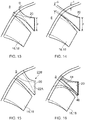
- Figure 13 One such measure is shown in Figure 13 , in which the circumferential width w of the flow control wall 20 is increased at the junction between the nozzle body 8 and the flow control wall 20. This increased width w means that the flow control wall 20 has a profile which increases in radial depth d but decreases in circumferential width w in the downstream direction.
- Figure 14 shows an alternative configuration in which the radial depth d 1 of the flow control wall 20 at its junction with the nozzle body 8 is increased, and the region of the junction extends, in the upstream direction, into the nozzle body 8.
- the nozzle body 8 is part of the nacelle 2, and so may have an increasing thickness in the upstream direction away from the edge at which the slats 16, 18 and the flow control walls 20 are provided. Consequently, the embodiment of Figure 14 provides a greater degree of support for the flow control walls 20.
- Figure 15 shows a variant of the embodiment shown in Figure 13 .
- all of the movable slats 16, 18 have a trapezoidal shape, broadening in the circumferential direction with increased axial distance from the nozzle body 8. Since the flow control walls 20 are symmetrical about respective radial planes, the slats 16, 18 on each side of each flow control wall 20 are identical.
- the flow control wall 20 is not symmetrical, but has a flow control surface 22A on one side which lies in a radial plane, and a flow control surface 22B on the other side which is oblique with respect to the engine axis X.
- the slat 16, 18 on the side of the flow control wall 20 having the radial flow control 22A is substantially rectangular (assuming that the flow control surface on the other side of the slat 16, 18 is also radial), while the slats 16, 18 between oblique flow control surfaces 22B will be trapezoidal.
- one or more additional strengthening webs 44 may be provided, extending between the flow control wall 20 and the nozzle body 8.
- the strengthening web 44 has a curved outer edge 46 which is shaped so as to minimise disruption of the gas flow over the slats 16, 18.
- the web 44 is shown on one side only of the flow control wall 20, and extends beneath (i.e. radially inwards of) the slat 16, 18.
- a corresponding web 44 may be provided on the opposite side of the flow control wall 20 extending radially inwardly of the adjacent slat 16, 18.
- strengthening webs 44 may be disposed above the respective slats 16, 18, so that the respective slats 16, 18 are disposed between them.
- the webs 44 extend along the radially inner and outer edges of the flow control walls 20. The webs 44 may serve to limit the displacement of the slats 16, 18, and to define their profile in the limit positions.
- Figure 17 shows an embodiment in which the fixed slats 14 (see Figure 1 ) between adjacent movable slats 16, 18 are profiled so that an offset region is provided between the respective flow control walls 20.
- the fixed slat 14 has axially extending regions 48, 50 which are radially offset from each other and are interconnected by a radially extending wall 52.
- the flow control walls, the axially extending regions 48, 50 and the radial wall 52 thus form axially extending channels 54, 56 which are disposed circumferentially side-by-side, and open respectively radially inwardly and radially outwardly with respect to the engine axis X.
- This profile of the fixed slat 14 provides additional stiffness to the structure, without creating a significant drag penalty.
- the area-reducing movable slat 16 is in its radially inwards limit position while the area-increasing movable slat 18 is shown in its radially outer limit position.
- the slats 16, 18 are made from, or incorporate, a shape memory material, such as a shape memory alloy, and the slats 16, 18 are provided with heating means for controlling heating of the slats 16, 18 to a temperature above the transition temperature of the material. Consequently, by control of the heating means, the respective slat 16, 18 can be caused to deform from its nominal position as shown, for example, in Figure 2 , to its radially displaced condition.
- a shape memory material such as a shape memory alloy
- FIG. 18 Alternative means for displacing the movable slat 16, 18 may be provided, for example as shown in Figure 18 , in which the slat 16, 18 is hinged at 23 in a conventional manner to the nozzle body 8, for actuation by a suitable actuating mechanism.
- Figure 18 an area-increasing slat 18 is shown, movable from a nominal position shown in full outline to an area-increased position shown in dashed outline. It will be appreciated that the same operating principle can be applied also to an area-reducing slat 16.
- the slats 16, 18 have been described as displaceable with respect to the nozzle body 8 about an axis, or an effective axis, which extends tangentially with respect to the engine axis X. Nevertheless, the principles underlying the present invention may also be applied to movable slats which are mounted on fixed slats 14 for pivoting about axially extending axes at the circumferential edges of the fixed slats 14. Any suitable actuator mechanism may be provided, as alternatives to the use of shape memory materials and hinged slats as described above. For example externally actuated morphing slats may be employed.
- the nozzle body 8 described is curved, and generally circular, although the profile of the nozzle body 8 at its junction with the slats 14, 16, 18 will be faceted in order to accommodate the slats 16, 18. It will be appreciated that the principles underlying the present invention can be applied also to non-circular exit nozzles 6, for example exhaust nozzles having rectangular or rectilinear shapes. It will be appreciated also that the principles underlying the present invention can be applied to core engine exhaust nozzles 10, which is however not part of the present invention, as well as bypass exhaust nozzles 6.
Landscapes
- Engineering & Computer Science (AREA)
- Chemical & Material Sciences (AREA)
- Combustion & Propulsion (AREA)
- Mechanical Engineering (AREA)
- General Engineering & Computer Science (AREA)
- Supercharger (AREA)
- Control Of Turbines (AREA)
Claims (15)
- Buse d'évacuation (10) de moteur de turbine à gaz possédant une sortie de buse (6), et comprenant un corps de buse (8), et une pluralité de lattes (16:18) déployées globalement dans le sens axial du corps de la buse (8) et distribuées de façon circonférentielle autour de la sortie de buse (6), au moins certaines des lattes (16:18) pouvant être déplacées vers l'intérieur et/ou vers l'extérieur relativement à un axe de la buse (X), des surfaces de régulation du flux à extension radiale (22) étant pratiquées sur des parois de régulation du flux (20) fixes relativement à l'axe de la buse (X), les parois de régulation du flux (20) étant disposées entre des lattes adjacentes des lattes mobiles (16:18), les bords circonférentiels respectifs des lattes adjacentes (16:18) pouvant être déplacées sur les surfaces de régulation du flux respectives disposées à l'opposé (22) des parois de régulation du flux communes (20) respectives, et des bords circonférentiels des lattes mobiles (16:18) se déplaçant sur les surfaces de régulation du flux (22) au cours du mouvement des lattes (16:18),
caractérisée en ce qu'une surface tournée radialement vers l'intérieur de chaque latte mobile (16:18) est configurée pour recevoir un flux d'évacuation d'une soufflante canalisée, et une surface tournée radialement vers l'extérieur de chaque latte mobile (16:18) est configurée pour recevoir un flux d'air sur une nacelle (2). - Buse d'évacuation (10) de moteur de turbine à gaz selon la revendication 1, dans laquelle les surfaces de régulation du flux (22) se prolongent sur la plage intégrale du mouvement des bords circonférentiels d'au moins certaines des lattes mobiles (16:18).
- Buse d'évacuation (10) de moteur de turbine à gaz selon la revendication 1 ou 2, dans laquelle les surfaces de régulation du flux (22) se prolongent sur une partie seulement de la plage du mouvement des bords circonférentiels d'au moins certaines des lattes mobiles (16:18).
- Buse d'évacuation (10) de moteur de turbine à gaz selon une quelconque des revendications précédentes, dans laquelle chaque latte mobile (16:18) peut être déplacée entre une position nominale et une position à surface ajustée.
- Buse d'évacuation (10) de moteur de turbine à gaz selon la revendication 4, dans laquelle chaque latte mobile (16:18) peut être déplacée d'une position nominale à des positions respectives à surface ajustée dans des directions radiales opposées depuis la position nominale.
- Buse d'évacuation (10) de moteur de turbine à gaz selon la revendication 4 ou 5, dans laquelle la position nominale de chaque latte mobile (16:18) correspond à une surface optimale de sortie de buse pour des conditions d'utilisation de croisière du moteur.
- Buse d'évacuation (10) de moteur de turbine à gaz selon la revendication 1, dans laquelle un dispositif de coopération est placé sur les lattes mobiles (16:18) et sur les parois de régulation du flux (20) pour arrêter le mouvement des lattes mobiles (16:18) sur des positions limites.
- Buse d'évacuation (10) de moteur de turbine à gaz selon la revendication 7, dans laquelle le dispositif de coopération (26, 28) comprend un mécanisme de verrouillage.
- Buse d'évacuation (10) de moteur de turbine à gaz selon la revendication 8, dans laquelle le mécanisme de verrouillage comprend, dans la paroi de régulation du flux (20), un évidement de verrouillage (40) pouvant être engagé par un élément de verrouillage (42) sur la latte (16:18) respective.
- Buse d'évacuation (10) de moteur de turbine à gaz selon une quelconque des revendications 7 à 9, dans laquelle les parois de régulation du flux (20) sont portées par le corps de buse (8), et s'étendent entre des lattes adjacentes parmi les lattes mobiles (16:18).
- Buse d'évacuation (10) de moteur de turbine à gaz selon la revendication 10, la dimension radiale de chaque paroi de régulation du flux (20), à sa jonction avec le corps de buse (8), étant supérieure à l'épaisseur radiale du corps de buse (8) à la jonction.
- Buse d'évacuation (10) de moteur de turbine à gaz selon une quelconque des revendications 7 à 11, dans laquelle au moins une partie d'au moins certaines des parois de régulation du flux (20) peuvent pivoter relativement au corps de buse (8) de façon à être parallèle à une latte (16:18) adjacente.
- Buse d'évacuation (10) de moteur de turbine à gaz selon une quelconque des revendications précédentes, dans laquelle un élément d'étanchéité (32) est pratiqué à chaque bord circonférentiel de chaque latte mobile (16:18), l'élément d'étanchéité (32) étant en contact par coulissement avec la surface de régulation du flux (22) adjacente.
- Moteur de turbine à gaz comprenant une buse d'évacuation (10) selon une quelconque des revendications 1 à 13.
- Moteur de turbine à gaz selon la revendication 14, le moteur de turbine à gaz comprenant en outre une nacelle (2), la partie postérieure de la nacelle (2) comprenant le corps (8) de la buse d'évacuation (10).
Applications Claiming Priority (1)
| Application Number | Priority Date | Filing Date | Title |
|---|---|---|---|
| GBGB1112045.8A GB201112045D0 (en) | 2011-07-14 | 2011-07-14 | A gas turbine engine exhaust nozzle |
Publications (3)
| Publication Number | Publication Date |
|---|---|
| EP2546505A2 EP2546505A2 (fr) | 2013-01-16 |
| EP2546505A3 EP2546505A3 (fr) | 2014-08-27 |
| EP2546505B1 true EP2546505B1 (fr) | 2019-10-02 |
Family
ID=44586537
Family Applications (1)
| Application Number | Title | Priority Date | Filing Date |
|---|---|---|---|
| EP12174092.2A Active EP2546505B1 (fr) | 2011-07-14 | 2012-06-28 | Tuyère d'échappement de moteur à turbine à gaz et moteur à turbine à gaz associé |
Country Status (3)
| Country | Link |
|---|---|
| US (1) | US9145846B2 (fr) |
| EP (1) | EP2546505B1 (fr) |
| GB (1) | GB201112045D0 (fr) |
Cited By (2)
| Publication number | Priority date | Publication date | Assignee | Title |
|---|---|---|---|---|
| RU2732360C1 (ru) * | 2019-09-27 | 2020-09-15 | Федеральное государственное унитарное предприятие "Центральный аэрогидродинамический институт имени профессора Н.Е. Жуковского" | Шумоглушащее сопло воздушно-реактивного двигателя |
| RU234687U1 (ru) * | 2024-11-01 | 2025-06-05 | Федеральное государственное бюджетное учреждение "Национальный исследовательский центр "Институт имени Н.Е. Жуковского" | Плоское сопло с обратным клином |
Families Citing this family (10)
| Publication number | Priority date | Publication date | Assignee | Title |
|---|---|---|---|---|
| ITRM20130473A1 (it) * | 2013-08-12 | 2013-11-11 | Unit 1 Srl | Convertiplano con nuove soluzionitecniche ed aerodinamiche atte a rendere sicuro e fruibile il mezzo anche in soluzioni di velivolo ultraleggero |
| JP6183837B2 (ja) * | 2013-08-19 | 2017-08-23 | 国立研究開発法人宇宙航空研究開発機構 | 排気ノズル |
| FR3095675B1 (fr) * | 2019-05-03 | 2021-04-09 | Safran Aircraft Engines | Mélangeur à flux séparés de turbomachine |
| CN112922862A (zh) * | 2019-12-06 | 2021-06-08 | 技嘉科技股份有限公司 | 风扇模块及包含其的散热系统 |
| FR3107559A1 (fr) * | 2020-02-24 | 2021-08-27 | Airbus Operations | Structure interne d’un conduit d’ejection primaire comportant un separateur dont la geometrie varie en fonction de la temperature |
| US12110841B2 (en) * | 2021-02-24 | 2024-10-08 | Japan Aerospace Exploration Agency | Supersonic aircraft and method of reducing sonic booms and jet noise |
| US20220325678A1 (en) * | 2021-04-08 | 2022-10-13 | Boom Technology, Inc. | Lobed mixer nozzles for supersonic and subsonic aircraft, and associated systems and methods |
| FR3127788B1 (fr) * | 2021-10-04 | 2025-03-21 | Safran Aircraft Engines | Tuyère de sortie équipée de chevrons pour propulseur aéronautique |
| US12162618B2 (en) | 2021-10-11 | 2024-12-10 | Boom Technology, Inc. | Dissimilarly shaped aircraft nozzles with tandem mixing devices, and associated systems and methods |
| GB202213335D0 (en) * | 2022-09-13 | 2022-10-26 | Rolls Royce Plc | An exhaust nozzle and a method of operating an exhaust nozzle |
Family Cites Families (19)
| Publication number | Priority date | Publication date | Assignee | Title |
|---|---|---|---|---|
| GB849502A (en) | 1957-03-01 | 1960-09-28 | Rolls Royce | Improvements in or relating to jet propulsion nozzles |
| DE1061569B (de) | 1957-11-14 | 1959-07-16 | Bmw Triebwerkbau Ges M B H | Konvergent-divergente Verstellschubduese fuer Strahltriebwerke |
| FR1177253A (fr) | 1958-07-14 | 1959-04-22 | Rolls Royce | Perfectionnements apportés aux tuyères de propulsion à réaction à section variable |
| FR1405358A (fr) * | 1964-05-27 | 1965-07-09 | Nord Aviation | Procédé et dispositif de mélange rapide de fluides notamment sur un combiné turbostatoréacteur |
| US3892358A (en) | 1971-03-17 | 1975-07-01 | Gen Electric | Nozzle seal |
| FR2242568B2 (fr) * | 1973-08-31 | 1976-10-01 | Snecma | |
| US4132068A (en) * | 1975-04-30 | 1979-01-02 | The United States Of America As Represented By The United States National Aeronautics And Space Administration | Variable area exhaust nozzle |
| US4422524A (en) | 1982-03-22 | 1983-12-27 | Lockheed Corporation | Variable shape, fluid flow nozzle for sound suppression |
| US4575006A (en) * | 1983-06-13 | 1986-03-11 | United Technologies Corporation | Nozzle flap edge seal |
| US4575099A (en) | 1984-01-27 | 1986-03-11 | General Electric Company | High excursion seal with flexible membrane to prevent gas leakage through hinge |
| US4747543A (en) * | 1987-04-14 | 1988-05-31 | United Technologies Corporation | Nozzle flap cooling liner |
| US4934600A (en) * | 1988-12-14 | 1990-06-19 | General Electric Company | Exhaust nozzle thermal distortion control device |
| US5908159A (en) * | 1997-02-24 | 1999-06-01 | The Boeing Company | Aircraft chute ejector nozzle |
| GB0105349D0 (en) | 2001-03-03 | 2001-04-18 | Rolls Royce Plc | Gas turbine engine exhaust nozzle |
| US7377099B2 (en) | 2005-05-27 | 2008-05-27 | United Technologies Corporation | System and method for cooling lateral edge regions of a divergent seal of an axisymmetric nozzle |
| FR2888211B1 (fr) * | 2005-07-06 | 2008-11-14 | Snecma Propulsion Solide Sa | Dispositif et procede de pilotage en lacets pour tuyere a section de sortie rectangulaire |
| US7721551B2 (en) | 2006-06-29 | 2010-05-25 | United Technologies Corporation | Fan variable area nozzle for a gas turbine engine fan nacelle |
| US20100000220A1 (en) | 2006-10-12 | 2010-01-07 | Zaffir Chaudhry | Fan variable area nozzle with electromechanical actuator |
| GB0820175D0 (en) | 2008-11-05 | 2008-12-10 | Rolls Royce Plc | A gas turbine engine variable area exhuast nozzle |
-
2011
- 2011-07-14 GB GBGB1112045.8A patent/GB201112045D0/en not_active Ceased
-
2012
- 2012-06-28 US US13/536,293 patent/US9145846B2/en not_active Expired - Fee Related
- 2012-06-28 EP EP12174092.2A patent/EP2546505B1/fr active Active
Non-Patent Citations (1)
| Title |
|---|
| None * |
Cited By (2)
| Publication number | Priority date | Publication date | Assignee | Title |
|---|---|---|---|---|
| RU2732360C1 (ru) * | 2019-09-27 | 2020-09-15 | Федеральное государственное унитарное предприятие "Центральный аэрогидродинамический институт имени профессора Н.Е. Жуковского" | Шумоглушащее сопло воздушно-реактивного двигателя |
| RU234687U1 (ru) * | 2024-11-01 | 2025-06-05 | Федеральное государственное бюджетное учреждение "Национальный исследовательский центр "Институт имени Н.Е. Жуковского" | Плоское сопло с обратным клином |
Also Published As
| Publication number | Publication date |
|---|---|
| EP2546505A2 (fr) | 2013-01-16 |
| US20130017065A1 (en) | 2013-01-17 |
| GB201112045D0 (en) | 2011-08-31 |
| EP2546505A3 (fr) | 2014-08-27 |
| US9145846B2 (en) | 2015-09-29 |
Similar Documents
| Publication | Publication Date | Title |
|---|---|---|
| EP2546505B1 (fr) | Tuyère d'échappement de moteur à turbine à gaz et moteur à turbine à gaz associé | |
| RU2433290C2 (ru) | Узел вентилятора на лопасти, а также турбовентиляторный газотурбинный двигатель | |
| EP2504553B1 (fr) | Assemblage de nacelle pour capot de buse de soufflante à section variable d'une turbine à gaz | |
| EP3825538B1 (fr) | Rail de support pour buse de soufflante à section variable | |
| US8430203B2 (en) | Noise reduction device for turbojet nacelle with mobile chevrons, and associated nacelle | |
| EP2333282B1 (fr) | Raidisseurs de buse de ventilateur à zone variable et mise en place | |
| EP2060770B1 (fr) | Inverseur de poussée à portes | |
| EP2420665B1 (fr) | Buse de ventilateur à zone variable | |
| CN104011361B (zh) | 具有用于低风扇压力比的风扇可变面积喷嘴的燃气涡轮发动机 | |
| EP2730773A2 (fr) | Buse d'échappement de moteur de turbine à gaz | |
| US20110120078A1 (en) | Variable area fan nozzle track | |
| EP2643557A2 (fr) | Réducteur de débit à géométrie variable et échangeur thermique intégrés | |
| EP3812570B1 (fr) | Moteur à turbine à gaz à faible rapport de pression du ventilateur | |
| WO2013106223A1 (fr) | Moteur de turbine à gaz doté d'une architecture à engrenages | |
| EP3109483B1 (fr) | Dispositif de variation asynchrone du calage des aubes de soufflante pour l'inversion de poussée d'un moteur à turbine à gaz | |
| US12320260B2 (en) | Segmented variable fan outlet guide vane with cam assembly and unique actuation mechanisms | |
| US12398648B2 (en) | Segmented variable fan outlet guide vane with cam assembly and pass through actuation mechanisms | |
| EP3441601B1 (fr) | Butée d'inverseur de poussée de moteur à turbine | |
| EP3249203B1 (fr) | Nacelle de moteur de turbine à gaz d'aéronef | |
| CN113677596B (zh) | 使用包括具有活动部的进气管唇缘的涡轮喷射引擎短舱的进气管以增大反推力的方法 | |
| US20250257699A1 (en) | Reverse thrust turbofan engine | |
| EP2918777B1 (fr) | Méthode d'optimisation d'une aube pour l'atténuation du bruit | |
| WO2013154639A2 (fr) | Turbine à gaz dotée d'une efficience énergétique améliorée |
Legal Events
| Date | Code | Title | Description |
|---|---|---|---|
| PUAI | Public reference made under article 153(3) epc to a published international application that has entered the european phase |
Free format text: ORIGINAL CODE: 0009012 |
|
| AK | Designated contracting states |
Kind code of ref document: A2 Designated state(s): AL AT BE BG CH CY CZ DE DK EE ES FI FR GB GR HR HU IE IS IT LI LT LU LV MC MK MT NL NO PL PT RO RS SE SI SK SM TR |
|
| AX | Request for extension of the european patent |
Extension state: BA ME |
|
| PUAL | Search report despatched |
Free format text: ORIGINAL CODE: 0009013 |
|
| AK | Designated contracting states |
Kind code of ref document: A3 Designated state(s): AL AT BE BG CH CY CZ DE DK EE ES FI FR GB GR HR HU IE IS IT LI LT LU LV MC MK MT NL NO PL PT RO RS SE SI SK SM TR |
|
| AX | Request for extension of the european patent |
Extension state: BA ME |
|
| RIC1 | Information provided on ipc code assigned before grant |
Ipc: F02K 1/38 20060101ALI20140718BHEP Ipc: F02K 1/46 20060101ALI20140718BHEP Ipc: F02K 1/48 20060101ALN20140718BHEP Ipc: F02K 1/12 20060101AFI20140718BHEP Ipc: F02K 1/80 20060101ALN20140718BHEP Ipc: F02K 1/00 20060101ALI20140718BHEP |
|
| 17P | Request for examination filed |
Effective date: 20150210 |
|
| RBV | Designated contracting states (corrected) |
Designated state(s): AL AT BE BG CH CY CZ DE DK EE ES FI FR GB GR HR HU IE IS IT LI LT LU LV MC MK MT NL NO PL PT RO RS SE SI SK SM TR |
|
| RAP1 | Party data changed (applicant data changed or rights of an application transferred) |
Owner name: ROLLS-ROYCE PLC |
|
| GRAP | Despatch of communication of intention to grant a patent |
Free format text: ORIGINAL CODE: EPIDOSNIGR1 |
|
| STAA | Information on the status of an ep patent application or granted ep patent |
Free format text: STATUS: GRANT OF PATENT IS INTENDED |
|
| RIC1 | Information provided on ipc code assigned before grant |
Ipc: F02K 1/80 20060101ALN20190718BHEP Ipc: F02K 1/38 20060101ALI20190718BHEP Ipc: F02K 1/48 20060101ALN20190718BHEP Ipc: F02K 1/46 20060101ALI20190718BHEP Ipc: F02K 1/12 20060101AFI20190718BHEP Ipc: F02K 1/00 20060101ALI20190718BHEP |
|
| GRAS | Grant fee paid |
Free format text: ORIGINAL CODE: EPIDOSNIGR3 |
|
| GRAA | (expected) grant |
Free format text: ORIGINAL CODE: 0009210 |
|
| STAA | Information on the status of an ep patent application or granted ep patent |
Free format text: STATUS: THE PATENT HAS BEEN GRANTED |
|
| INTG | Intention to grant announced |
Effective date: 20190807 |
|
| AK | Designated contracting states |
Kind code of ref document: B1 Designated state(s): AL AT BE BG CH CY CZ DE DK EE ES FI FR GB GR HR HU IE IS IT LI LT LU LV MC MK MT NL NO PL PT RO RS SE SI SK SM TR |
|
| REG | Reference to a national code |
Ref country code: GB Ref legal event code: FG4D |
|
| REG | Reference to a national code |
Ref country code: AT Ref legal event code: REF Ref document number: 1186429 Country of ref document: AT Kind code of ref document: T Effective date: 20191015 Ref country code: CH Ref legal event code: EP |
|
| REG | Reference to a national code |
Ref country code: DE Ref legal event code: R096 Ref document number: 602012064448 Country of ref document: DE |
|
| REG | Reference to a national code |
Ref country code: IE Ref legal event code: FG4D |
|
| REG | Reference to a national code |
Ref country code: NL Ref legal event code: MP Effective date: 20191002 |
|
| REG | Reference to a national code |
Ref country code: LT Ref legal event code: MG4D |
|
| RAP2 | Party data changed (patent owner data changed or rights of a patent transferred) |
Owner name: ROLLS-ROYCE PLC |
|
| REG | Reference to a national code |
Ref country code: AT Ref legal event code: MK05 Ref document number: 1186429 Country of ref document: AT Kind code of ref document: T Effective date: 20191002 |
|
| PG25 | Lapsed in a contracting state [announced via postgrant information from national office to epo] |
Ref country code: ES Free format text: LAPSE BECAUSE OF FAILURE TO SUBMIT A TRANSLATION OF THE DESCRIPTION OR TO PAY THE FEE WITHIN THE PRESCRIBED TIME-LIMIT Effective date: 20191002 Ref country code: LT Free format text: LAPSE BECAUSE OF FAILURE TO SUBMIT A TRANSLATION OF THE DESCRIPTION OR TO PAY THE FEE WITHIN THE PRESCRIBED TIME-LIMIT Effective date: 20191002 Ref country code: NL Free format text: LAPSE BECAUSE OF FAILURE TO SUBMIT A TRANSLATION OF THE DESCRIPTION OR TO PAY THE FEE WITHIN THE PRESCRIBED TIME-LIMIT Effective date: 20191002 Ref country code: PT Free format text: LAPSE BECAUSE OF FAILURE TO SUBMIT A TRANSLATION OF THE DESCRIPTION OR TO PAY THE FEE WITHIN THE PRESCRIBED TIME-LIMIT Effective date: 20200203 Ref country code: BG Free format text: LAPSE BECAUSE OF FAILURE TO SUBMIT A TRANSLATION OF THE DESCRIPTION OR TO PAY THE FEE WITHIN THE PRESCRIBED TIME-LIMIT Effective date: 20200102 Ref country code: FI Free format text: LAPSE BECAUSE OF FAILURE TO SUBMIT A TRANSLATION OF THE DESCRIPTION OR TO PAY THE FEE WITHIN THE PRESCRIBED TIME-LIMIT Effective date: 20191002 Ref country code: AT Free format text: LAPSE BECAUSE OF FAILURE TO SUBMIT A TRANSLATION OF THE DESCRIPTION OR TO PAY THE FEE WITHIN THE PRESCRIBED TIME-LIMIT Effective date: 20191002 Ref country code: SE Free format text: LAPSE BECAUSE OF FAILURE TO SUBMIT A TRANSLATION OF THE DESCRIPTION OR TO PAY THE FEE WITHIN THE PRESCRIBED TIME-LIMIT Effective date: 20191002 Ref country code: LV Free format text: LAPSE BECAUSE OF FAILURE TO SUBMIT A TRANSLATION OF THE DESCRIPTION OR TO PAY THE FEE WITHIN THE PRESCRIBED TIME-LIMIT Effective date: 20191002 Ref country code: GR Free format text: LAPSE BECAUSE OF FAILURE TO SUBMIT A TRANSLATION OF THE DESCRIPTION OR TO PAY THE FEE WITHIN THE PRESCRIBED TIME-LIMIT Effective date: 20200103 Ref country code: PL Free format text: LAPSE BECAUSE OF FAILURE TO SUBMIT A TRANSLATION OF THE DESCRIPTION OR TO PAY THE FEE WITHIN THE PRESCRIBED TIME-LIMIT Effective date: 20191002 Ref country code: NO Free format text: LAPSE BECAUSE OF FAILURE TO SUBMIT A TRANSLATION OF THE DESCRIPTION OR TO PAY THE FEE WITHIN THE PRESCRIBED TIME-LIMIT Effective date: 20200102 |
|
| PG25 | Lapsed in a contracting state [announced via postgrant information from national office to epo] |
Ref country code: RS Free format text: LAPSE BECAUSE OF FAILURE TO SUBMIT A TRANSLATION OF THE DESCRIPTION OR TO PAY THE FEE WITHIN THE PRESCRIBED TIME-LIMIT Effective date: 20191002 Ref country code: HR Free format text: LAPSE BECAUSE OF FAILURE TO SUBMIT A TRANSLATION OF THE DESCRIPTION OR TO PAY THE FEE WITHIN THE PRESCRIBED TIME-LIMIT Effective date: 20191002 Ref country code: CZ Free format text: LAPSE BECAUSE OF FAILURE TO SUBMIT A TRANSLATION OF THE DESCRIPTION OR TO PAY THE FEE WITHIN THE PRESCRIBED TIME-LIMIT Effective date: 20191002 Ref country code: IS Free format text: LAPSE BECAUSE OF FAILURE TO SUBMIT A TRANSLATION OF THE DESCRIPTION OR TO PAY THE FEE WITHIN THE PRESCRIBED TIME-LIMIT Effective date: 20200224 |
|
| PG25 | Lapsed in a contracting state [announced via postgrant information from national office to epo] |
Ref country code: AL Free format text: LAPSE BECAUSE OF FAILURE TO SUBMIT A TRANSLATION OF THE DESCRIPTION OR TO PAY THE FEE WITHIN THE PRESCRIBED TIME-LIMIT Effective date: 20191002 |
|
| REG | Reference to a national code |
Ref country code: DE Ref legal event code: R097 Ref document number: 602012064448 Country of ref document: DE |
|
| PG2D | Information on lapse in contracting state deleted |
Ref country code: IS |
|
| PG25 | Lapsed in a contracting state [announced via postgrant information from national office to epo] |
Ref country code: IS Free format text: LAPSE BECAUSE OF FAILURE TO SUBMIT A TRANSLATION OF THE DESCRIPTION OR TO PAY THE FEE WITHIN THE PRESCRIBED TIME-LIMIT Effective date: 20200202 Ref country code: DK Free format text: LAPSE BECAUSE OF FAILURE TO SUBMIT A TRANSLATION OF THE DESCRIPTION OR TO PAY THE FEE WITHIN THE PRESCRIBED TIME-LIMIT Effective date: 20191002 Ref country code: EE Free format text: LAPSE BECAUSE OF FAILURE TO SUBMIT A TRANSLATION OF THE DESCRIPTION OR TO PAY THE FEE WITHIN THE PRESCRIBED TIME-LIMIT Effective date: 20191002 Ref country code: RO Free format text: LAPSE BECAUSE OF FAILURE TO SUBMIT A TRANSLATION OF THE DESCRIPTION OR TO PAY THE FEE WITHIN THE PRESCRIBED TIME-LIMIT Effective date: 20191002 |
|
| PLBE | No opposition filed within time limit |
Free format text: ORIGINAL CODE: 0009261 |
|
| STAA | Information on the status of an ep patent application or granted ep patent |
Free format text: STATUS: NO OPPOSITION FILED WITHIN TIME LIMIT |
|
| PG25 | Lapsed in a contracting state [announced via postgrant information from national office to epo] |
Ref country code: SK Free format text: LAPSE BECAUSE OF FAILURE TO SUBMIT A TRANSLATION OF THE DESCRIPTION OR TO PAY THE FEE WITHIN THE PRESCRIBED TIME-LIMIT Effective date: 20191002 Ref country code: SM Free format text: LAPSE BECAUSE OF FAILURE TO SUBMIT A TRANSLATION OF THE DESCRIPTION OR TO PAY THE FEE WITHIN THE PRESCRIBED TIME-LIMIT Effective date: 20191002 Ref country code: IT Free format text: LAPSE BECAUSE OF FAILURE TO SUBMIT A TRANSLATION OF THE DESCRIPTION OR TO PAY THE FEE WITHIN THE PRESCRIBED TIME-LIMIT Effective date: 20191002 |
|
| 26N | No opposition filed |
Effective date: 20200703 |
|
| PG25 | Lapsed in a contracting state [announced via postgrant information from national office to epo] |
Ref country code: SI Free format text: LAPSE BECAUSE OF FAILURE TO SUBMIT A TRANSLATION OF THE DESCRIPTION OR TO PAY THE FEE WITHIN THE PRESCRIBED TIME-LIMIT Effective date: 20191002 |
|
| REG | Reference to a national code |
Ref country code: DE Ref legal event code: R119 Ref document number: 602012064448 Country of ref document: DE |
|
| PG25 | Lapsed in a contracting state [announced via postgrant information from national office to epo] |
Ref country code: MC Free format text: LAPSE BECAUSE OF FAILURE TO SUBMIT A TRANSLATION OF THE DESCRIPTION OR TO PAY THE FEE WITHIN THE PRESCRIBED TIME-LIMIT Effective date: 20191002 |
|
| REG | Reference to a national code |
Ref country code: CH Ref legal event code: PL |
|
| GBPC | Gb: european patent ceased through non-payment of renewal fee |
Effective date: 20200628 |
|
| PG25 | Lapsed in a contracting state [announced via postgrant information from national office to epo] |
Ref country code: LU Free format text: LAPSE BECAUSE OF NON-PAYMENT OF DUE FEES Effective date: 20200628 |
|
| REG | Reference to a national code |
Ref country code: BE Ref legal event code: MM Effective date: 20200630 |
|
| PG25 | Lapsed in a contracting state [announced via postgrant information from national office to epo] |
Ref country code: GB Free format text: LAPSE BECAUSE OF NON-PAYMENT OF DUE FEES Effective date: 20200628 Ref country code: FR Free format text: LAPSE BECAUSE OF NON-PAYMENT OF DUE FEES Effective date: 20200630 Ref country code: LI Free format text: LAPSE BECAUSE OF NON-PAYMENT OF DUE FEES Effective date: 20200630 Ref country code: IE Free format text: LAPSE BECAUSE OF NON-PAYMENT OF DUE FEES Effective date: 20200628 Ref country code: CH Free format text: LAPSE BECAUSE OF NON-PAYMENT OF DUE FEES Effective date: 20200630 |
|
| PG25 | Lapsed in a contracting state [announced via postgrant information from national office to epo] |
Ref country code: BE Free format text: LAPSE BECAUSE OF NON-PAYMENT OF DUE FEES Effective date: 20200630 Ref country code: DE Free format text: LAPSE BECAUSE OF NON-PAYMENT OF DUE FEES Effective date: 20210101 |
|
| PG25 | Lapsed in a contracting state [announced via postgrant information from national office to epo] |
Ref country code: TR Free format text: LAPSE BECAUSE OF FAILURE TO SUBMIT A TRANSLATION OF THE DESCRIPTION OR TO PAY THE FEE WITHIN THE PRESCRIBED TIME-LIMIT Effective date: 20191002 Ref country code: MT Free format text: LAPSE BECAUSE OF FAILURE TO SUBMIT A TRANSLATION OF THE DESCRIPTION OR TO PAY THE FEE WITHIN THE PRESCRIBED TIME-LIMIT Effective date: 20191002 Ref country code: CY Free format text: LAPSE BECAUSE OF FAILURE TO SUBMIT A TRANSLATION OF THE DESCRIPTION OR TO PAY THE FEE WITHIN THE PRESCRIBED TIME-LIMIT Effective date: 20191002 |
|
| PG25 | Lapsed in a contracting state [announced via postgrant information from national office to epo] |
Ref country code: MK Free format text: LAPSE BECAUSE OF FAILURE TO SUBMIT A TRANSLATION OF THE DESCRIPTION OR TO PAY THE FEE WITHIN THE PRESCRIBED TIME-LIMIT Effective date: 20191002 |