EP2546513A2 - Eolienne et roue de turbine associée - Google Patents
Eolienne et roue de turbine associée Download PDFInfo
- Publication number
- EP2546513A2 EP2546513A2 EP20120175942 EP12175942A EP2546513A2 EP 2546513 A2 EP2546513 A2 EP 2546513A2 EP 20120175942 EP20120175942 EP 20120175942 EP 12175942 A EP12175942 A EP 12175942A EP 2546513 A2 EP2546513 A2 EP 2546513A2
- Authority
- EP
- European Patent Office
- Prior art keywords
- turbine
- wind
- turbine wheel
- flow
- air
- Prior art date
- Legal status (The legal status is an assumption and is not a legal conclusion. Google has not performed a legal analysis and makes no representation as to the accuracy of the status listed.)
- Withdrawn
Links
- XLYOFNOQVPJJNP-UHFFFAOYSA-N water Substances O XLYOFNOQVPJJNP-UHFFFAOYSA-N 0.000 claims abstract description 29
- 230000001133 acceleration Effects 0.000 claims description 11
- 230000003247 decreasing effect Effects 0.000 claims description 4
- 238000010792 warming Methods 0.000 claims 1
- 238000000034 method Methods 0.000 abstract description 5
- 239000007789 gas Substances 0.000 abstract description 4
- 239000007788 liquid Substances 0.000 abstract description 3
- 238000004064 recycling Methods 0.000 abstract 1
- 239000003381 stabilizer Substances 0.000 abstract 1
- 238000006243 chemical reaction Methods 0.000 description 9
- 239000012530 fluid Substances 0.000 description 8
- 230000000694 effects Effects 0.000 description 3
- 238000004519 manufacturing process Methods 0.000 description 2
- 238000005457 optimization Methods 0.000 description 2
- 101100498160 Mus musculus Dach1 gene Proteins 0.000 description 1
- 239000003570 air Substances 0.000 description 1
- 238000000418 atomic force spectrum Methods 0.000 description 1
- 239000000969 carrier Substances 0.000 description 1
- 230000000295 complement effect Effects 0.000 description 1
- 230000005611 electricity Effects 0.000 description 1
- 230000002349 favourable effect Effects 0.000 description 1
- 238000009434 installation Methods 0.000 description 1
- 230000001788 irregular Effects 0.000 description 1
- 238000012986 modification Methods 0.000 description 1
- 230000004048 modification Effects 0.000 description 1
- 238000011084 recovery Methods 0.000 description 1
- 230000000630 rising effect Effects 0.000 description 1
- 239000007787 solid Substances 0.000 description 1
- 238000009987 spinning Methods 0.000 description 1
- 239000013589 supplement Substances 0.000 description 1
- 239000003643 water by type Substances 0.000 description 1
Images





Classifications
-
- F—MECHANICAL ENGINEERING; LIGHTING; HEATING; WEAPONS; BLASTING
- F03—MACHINES OR ENGINES FOR LIQUIDS; WIND, SPRING, OR WEIGHT MOTORS; PRODUCING MECHANICAL POWER OR A REACTIVE PROPULSIVE THRUST, NOT OTHERWISE PROVIDED FOR
- F03D—WIND MOTORS
- F03D1/00—Wind motors with rotation axis substantially parallel to the air flow entering the rotor
- F03D1/06—Rotors
- F03D1/0608—Rotors characterised by their aerodynamic shape
-
- Y—GENERAL TAGGING OF NEW TECHNOLOGICAL DEVELOPMENTS; GENERAL TAGGING OF CROSS-SECTIONAL TECHNOLOGIES SPANNING OVER SEVERAL SECTIONS OF THE IPC; TECHNICAL SUBJECTS COVERED BY FORMER USPC CROSS-REFERENCE ART COLLECTIONS [XRACs] AND DIGESTS
- Y02—TECHNOLOGIES OR APPLICATIONS FOR MITIGATION OR ADAPTATION AGAINST CLIMATE CHANGE
- Y02E—REDUCTION OF GREENHOUSE GAS [GHG] EMISSIONS, RELATED TO ENERGY GENERATION, TRANSMISSION OR DISTRIBUTION
- Y02E10/00—Energy generation through renewable energy sources
- Y02E10/70—Wind energy
- Y02E10/72—Wind turbines with rotation axis in wind direction
Definitions
- the present invention relates to a wind turbine with the features of independent claim 1.
- Wind turbines which have become known in various embodiments.
- the most well-known and almost exclusively used for large systems variant are standing on masts, axially flowed and flowed through rotors with two or three rotor blades, the rotor interacts either directly or via a reduction gear with an electric generator.
- the diameter of these rotors can be up to 90 meters or even more in so-called large-scale systems.
- there are numerous smaller plants with lower power which are mainly used for decentralized energy supply and / or to supplement other energy sources.
- a similar turbine for use in vehicles to gain energy while driving is from the DE 20 2009 013 425 U1 known.
- An additional feed hopper is to improve the flow of the turbine by steering the inflow flow.
- the DE 10 2005 049 794 A1 discloses a propeller having baffles on the surfaces of its propeller blades intended to provide improved axial deflection of the incoming fluid to the surfaces of the propeller blades and for improved axial discharge downstream of the propeller blade.
- the turbulence occurring behind the propeller area should be reduced.
- the guide structures have arcuate curvature and extend in the direction of rotation of the propeller.
- a compact wind turbine which should be particularly suitable for private users, is in the DE 10 2008 025 719 A1 proposed.
- An axially flowing air stream impinges on a drive disk with the rotation axis arranged around and perpendicular slats protruding from the drive disk, so that the air flow is discharged radially while driving the drive disk.
- the drive pulley is received in a housing having an axial inlet and a radial outlet.
- the DE 10 2008 046 209 A1 finally discloses a turbine wheel for gaseous media, in particular for a wind flow, which is fed axially centered to the impeller, where it is deflected in the region of the impeller base and then flows through the blade grid from the inside to the outside.
- the turbine runner is connected to a generator which is used to generate electricity.
- An object of the invention is to provide an impeller for a wind turbine, which is axially impinged and radially deflects the air under rotary drive of the impeller, which has an improved efficiency compared to known through an improved design of the impellers and / or guide surfaces.
- the invention proposes a wind power plant for converting flow energy transported by air into rotary mechanical and / or electrical energy, which comprises at least one turbine runner that flows essentially axially and leaves the air in approximately the radial direction.
- This turbine wheel has a rotatably mounted disk-shaped carrier with a flow-guiding structure in the form of obliquely and / or curved webs and / or channels. It is envisaged that the webs or channels each have variable or changing cross sections over their longitudinal course.
- variable cross sections of the webs, channels or the air-conducting profilings in the turbine runner may in particular resemble an airfoil profile and have an initially increasing and then decreasing thickness or thickness of the cross section in the flow direction.
- the webs the transfer of the flow energy of the fluid flowing through the impeller - the wind, water o. The like. - Partially referred to as sliding vanes.
- the terms "webs", “wings”, “glides” etc. are therefore usually to be regarded as synonyms.
- wind turbine or “wind turbine” is therefore to be understood as meaning that it may also mean hydropower plants or water turbines which operate on the same principle of flow deflection from axial flow into radial flow.
- the turbine or turbine runner of the wind turbine according to the invention has a plurality of approximately uniformly distributed over the outer region of the front surface webs - also referred to as sliding surfaces or sliding - on whose surfaces each have a curved course whose curvature in particular can correspond to the predetermined curve of a Coriolis acceleration.
- This provides a mode of energy production from the flow energy of air, gases and fluids by means of at least one turbine impeller, which follows or at least resembles the principle of Coriolis acceleration. In this way, extremely compact wind energy or water power plants can be provided, which have a high efficiency and a high energy density.
- the sailing characteristics also apply because a light vehicle equipped with a cylinder turbine can, with appropriate reduction, drive against the wind solely with the energy contained in the moving air.
- the possibility of recovering drive energy in different vehicles is used as a savings option of energy.
- the displaced by a motor vehicle medium gives its resulting from the drive kinetic energy almost exclusively to the environment (eg wind pressure and moving plants on the roadside) from.
- the airstream represents an energy form caused by the vehicle itself, which one seeks to reduce by a favorable CW value, but at the same time represents a potential for recovery, which is at least partially usable.
- the turbine wheel of the wind power plant according to the invention can optionally have a plurality of approximately uniformly distributed over the outer region of the front surface webs, sliding surfaces or wings whose cross-section each having a profiling, wherein the surfaces each have a curved course with different curvature.
- not all webs must have an identical profiling, but may possibly also be designed differently.
- embodiments are conceivable in which only every second web or sliding wing has a corresponding profiling, while each second web has a constant cross-section.
- the total curvature of the webs preferably follows approximately the course of the Coriolis acceleration.
- each web has a greater curvature on its convex outer surface than on its concave inner side, a thickness decreasing towards the lateral ends of each web relative to the central region results, giving the webs a cross section similar to the cross sections of aircraft wings or the like .
- the webs of the turbine wheel may each have hypoid or hypoid-like courses. The characteristic of these curves is that the webs, each extending from a smaller radius of the turbine wheel to its outer radius, respectively have a uniform or outwardly decreasing curvature having approximately a hypoid shape, so that the turbine wheel in a plan view resembles a gear with hypiodförmiger spur toothing.
- the webs of the turbine impeller according to the invention on their end faces facing away from the disc-shaped support one or more deflectors in the form of an annular disc, individual repeller-like deflector, flow-guiding discs o.
- the turbine wheel is assigned a flow-directing channel, which has a sectionally curved course.
- the channel may have a substantially horizontal air inlet and a substantially vertical air outlet which opens at the flow inlet of the turbine wheel arranged horizontally and rotating about a substantially vertically arranged axis.
- this channel is tuned in cross-section to the diameter of the turbine wheel and optionally has a guide for rotation against the wind direction, so that the channel mouth can always remain directed in the wind.
- a further variant of the wind power plant can provide that the turbine wheel, which is arranged horizontally on a building and rotates about an essentially vertically arranged axis, flows from below, wherein air ducts conduct warm exhaust air from the building to the turbine wheel.
- a mobile wind power plant can provide that at least one substantially vertically arranged and about a substantially horizontally disposed axis rotating turbine wheel mounted on a land, water or aircraft and is flowed by the wind and / or air currents.
- the invention comprises not only the wind turbine itself, but also the rotating turbine wheel or turbine runner of air flowed in the axial direction of such a wind turbine according to one of the previously described embodiments.
- the invention also includes such a turbine wheel, which is constructed according to one of the previously described embodiments and has been supplied with water in order to convert the kinetic energy of the water into mechanical rotational energy and / or into electrical energy.
- the present invention relates not only to a wind turbine or hydropower plant and the turbine wheel required for the energy conversion, but also to a method for generating energy from moving fluids and gases with turbines on the principle of Coriolis acceleration, which is characterized in that the flowing liquids or Gases axially on a round and disc-shaped support meet, on which, by web-like elevations, called sliding vanes, or groove-like depressions, called sliding channels, which is given by the Coriolis force curve, so that the respective medium in the sum radially and perpendicular expels to the outside and thereby accelerates the carrier tangentially in the direction determined by the curve.
- This principle is based on a rotating disk on which a body experiences an outward centrifugal force. In this case, the curve described by the Coriolis force is given, which in turn causes the disc in the axial impact of a medium in rotation.
- the process for energy production or energy conversion uses a so-called cylinder turbine with Gleiterielprofilen that combine the Coriolis force with the Bernoulli effect.
- This turbine is flowed axially, wherein the flow takes place on a windproof carrier on which are axially mounted sliding wings with a wing profile similar to the aircraft wing, which are curved at the bottom of the Coriolis acceleration curve and is more curved on the overlying top.
- the profile side lying in front in the direction of rotation is, deviating from the aircraft wing profile, formed as an edge separating the air flow, the sum of which deflects the air flow at right angles and thus cause rotation on the support about the axis of rotation.
- the predetermined curve which corresponds approximately to the course of a Coriolis acceleration, causes on the underside of the sliding wings their rotation and deflection and thus a rotation of the carrier.
- the transverse profile with the curvature stronger at the top reinforces the buoyancy according to the Bernoulli effect and thus provides a rotational acceleration of the disc of the turbine wheel.
- the spaces between the glide wings with wind deflectors against the axially impinging flow can be shielded on the cylinder turbine such that the air flow exiting between the glides is not influenced and at the same time, due to the oblique position of the wind deflectors in the direction of rotation, the cylinders Turbine experiences an additional angular momentum.
- This variant of the cylinder turbine provides that also the buoyancy zone by wind deflector for Optimization of the system can help by the deflectors are repeller-like design and can be installed while shielding disturbing turbulence in the spaces between the sliding wings.
- the environment of the cylinder turbine including the buoyancy zone can be covered by a building wall or other components, wherein it can be located in an opening which lies just in front of the inner diameter.
- This possibility provides for the installation of the turbine in building walls or other solid wall surfaces or building facades or in other suitable areas or places.
- the wall can shield the buoyancy zone, but overall hardly contributes to the optimization.
- the cylinder turbine can be set up with its axis perpendicular to the wind direction, wherein a circularly rotatable windscreen can be located above the opening, which independently turns its opening into the wind with its wind vane and thereby moves it into the cylinder. Turbine deflects.
- a rotatable wind-catching pipe can, for example, also horizontal, ie with a vertical axis of rotation, e.g. be operated on roofs of buildings or on other suitable surfaces.
- the cylinder turbine can be placed with its axis perpendicular with its opening to the earth, in order to direct a heated air flow, which arises from different causes and is delimited with films or roofs, in the opening.
- a possibility is given to install a turbine runner at the highest point of a greenhouse or another warm air-generating building, without losses resulting from the conversion of heat into kinetic energy in a fireplace.
- Another possibility is to form a double-cylinder turbine, in which two identical or different - ie in particular equal or different dimension - cylinder turbines having opposite directions of rotation to combine, by opposing their openings with one Freewheel are firmly connected, the rotationally fixed against the direction of rotation sits on a shaft and allows only one direction of rotation of the shaft, so that with oscillating currents, the windward side of the leeward side not entrains.
- two wheels are combined in such a way that they adjoin one another with their carriers or are also spaced from one another in an aligned arrangement with a common shaft, so that their openings are opposite or facing away from each other.
- Combination makes it possible to transmit oscillating or non-uniform or alternating flows from different directions in the same rotation to a shaft.
- a freewheel can be installed on the shaft, so that a fixed direction of rotation is given, even if one of the rotors rotates in an opposite direction.
- a variant of the turbine wheel which deviates significantly from the variants and designs described above can provide a so-called Coriolis double cone, which is predominantly suitable for converting the flow energy of the water.
- Coriolis double cone which is predominantly suitable for converting the flow energy of the water.
- truncated cones which are firmly connected to a common base
- groove-like recesses in cross-section equal sliding channels introduced, which follow the curve of the Coriolis acceleration, wherein the same sliding channels are introduced in mirror image on the opposite truncated cone complementary , with the purpose to achieve a similar rotation in oscillating flows and waves.
- Such a Coriolis turbine on the basis of two connected with their bases truncated cones, on the lateral surfaces in the same cross-section channels are introduced, the opposite channels follow opposite or mirror-image curves, preferably serves the conversion of flow energy flowing water into rotational kinetic energy or into mechanical energy, which can be converted into electrical energy if necessary.
- the double cone In the case of axially fixed positioning with a vertical axis to the water level, the double cone produces a rotation in the same direction both when the water wave is swinging upwards and downwards.
- the Coriolis double cone can also be placed in the same direction with a horizontal axis in a surf area near the shore with rising water wave and the returning water.
- the turbine wheel can also be designed as a so-called.
- Coriolis blade turbine which is also mainly suitable for water as a flowing medium whose energy is converted into rotational kinetic energy.
- sliding surfaces are present, which are connected at right angles to the carrier and each follow the Coriolis curves.
- the sliding surfaces, which determine the direction of rotation are arranged parallel to the axis of rotation and are pulled close to the shaft to reduce the inlet opening as possible to the diameter of the shaft, wherein the axial height of the sliding surfaces from the center to the periphery decrease or increase.
- Such a Coriolis blade turbine with curved sliding surfaces is particularly suitable for use in slow-flowing waters, wherein at the same time a localized congestion is generated, which is used to drive the turbine wheel.
- the invention also makes it possible to recover drive energy from vehicle wind induced wind with turbines according to one of the variants described above.
- the claimed turbines can be mounted on vehicles and / or ships in places that are already exposed to high wind pressure to recover the energy generated by the wind energy partially back, or to use the energy of the wind on ships by swiveling in all directions the wind and to use the windproof support surface in certain conditions like a sail.
- the practical application of the energy conversion in moving and / or wind-exposed vehicles and ships is therefore possible, as the flow is deflected at right angles and thus the space on the lee side of the turbine wheel is provided to the vehicle.
- Fig. 1 illustrates the basic structure and essential features of the present invention. Shown is a schematic perspective view of a first embodiment of a turbine runner 15 of a wind turbine 30 according to the invention, while the Fig. 2 in a detail section of a portion of the turbine runner 15 according to Fig. 1 clarified.
- a rotating shaft 11 which acts as the output shaft of the wind turbine 30
- a disk-shaped carrier 1 is rotatably connected.
- the carrier 1 has a series of uniformly spaced and an outer edge of the carrier 1 overlapping Gleiterieln 2 or webs, which according to the present invention each have a uniform or irregular curvature and on their course a profiling (see. Fig. 3 ) exhibit.
- the curvature of the webs or glides 2 is in the FIGS. 1 and 2 clearly recognizable, but not the profiling, only from the Figures 3 ff. clearly shows.
- the side facing away from the carrier 1 end edges of the webs or glides 2 are limited in the embodiment shown by a ring or wind deflector 8, which acts as a buoyancy zone 3.
- the inner opening 10 of the ring or wind deflector 8 forms the axial inflow opening of the turbine 15, through which the driving fluid, the air or the water enters the turbine runner 15 and puts it in a rotation in the direction of rotation 5 about the axis of rotation 4, wherein the driving fluid simultaneously exits at the outer periphery of the impeller 15 between the webs or vanes 2 in the radial direction.
- the axial height 9, the length of the webs 2, the buoyancy angle 3 (see. Fig. 2 ) and the diameter 10 of the turbine 15 determine their performance.
- the schematic detail view of Fig. 2 illustrates once again a possible curvature of the webs or glides 2, which have a length with an angular segment 7, which may, for example, 20 to 30 degrees.
- the outer radius 6 of the turbine 15 defines its size, while the buoyancy zone 3 has a strong influence on the performance.
- FIG. 3 shows a further embodiment of the turbine runner 15.
- the reference numerals 12 illustrate the exit direction of the driving flow, which has previously entered the turbine 15 in the axial direction through the opening 10.
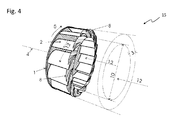
- the Fig. 4 shows a schematic perspective view of a third embodiment of the turbine runner 15.
- the buoyancy zone 3 is hereby optimized by wind deflector 8.
- This wind deflector 8 are formed by repeller-like wings on the front sides of the sliding vanes or webs 2. They should reduce disturbing turbulence in the spaces between the sliding wings 2 and shield.
- the Fig. 5 shows a schematic perspective view of an integrable in a building wall 16 turbine runner 15.
- the impeller 15 may in this case be installed in an only indicated here wall, such as. A house or building wall.
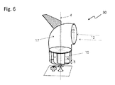
- the Fig. 6 shows a schematic perspective view of one on a building roof or other building or on flat surfaces mountable Wind turbine 30 with rotatable Windleitelement 17, which is designed as a 90 ° curved pipe socket, the outer opening 10 is horizontal and thereby deflect the wind 12 by 90 ° down towards the horizontal lying and rotating about the rotation axis 4 turbine wheel 15.
- the arranged on Windleitelement 17 flag ensures their rotation in the wind, so that the opening 10 is always directed against the wind direction 12.
- the Fig. 7 shows a schematic representation of an impinged from below impeller 15 which is mountable on a roof, which may be, for example, part of a greenhouse 25 or another building.
- the warm exhaust air 12 is directed in a horizontal direction - possibly from several sides - to the wind power plant 30 and deflected up there, so that the air can leave the impeller 15 to the side.
- FIG. 8 The schematic perspective view of Fig. 8 shows a tandem arrangement with two identical turbine wheels 15 which are coupled to a common shaft 11. Freewheels 14 can ensure that even with different flow and different wind direction 12 a same direction rotation 5 is guaranteed.
- the Fig. 9 shows a schematic representation of an alternative embodiment of a turbine runner 15, which is particularly suitable as a water turbine.
- a Coriolis turbine is formed on the basis of two truncated cones 18 and 19 connected to their base surfaces, in the lateral surfaces of which constant channels 20 are introduced in cross-section, the respective opposing channels 20 having opposite or mirror-image profiles.
- the Coriolis double cone can also be arranged with a horizontal axis in the surf area with accumulating water wave and the returning water.
- the Fig. 10 shows a schematic perspective view of a designed as a turbine blade turbine 23 water turbine, which is suitable as a so-called. Slow runner. The relatively long curved surfaces of the glides 2 make the slow flow turbine 12 seem suitable.
- the Fig. 11 shows a schematic representation of a vehicle 22 with frontally arranged turbine wheel 15 as a possible site of use of a wind turbine according to the invention 30.
- Die Fig. 12 shows a schematic representation a ship 24 with two deck mounted wind turbines 30 and turbine wheels 15 for energy conversion.
Landscapes
- Engineering & Computer Science (AREA)
- Physics & Mathematics (AREA)
- Fluid Mechanics (AREA)
- Life Sciences & Earth Sciences (AREA)
- Sustainable Development (AREA)
- Sustainable Energy (AREA)
- Chemical & Material Sciences (AREA)
- Combustion & Propulsion (AREA)
- Mechanical Engineering (AREA)
- General Engineering & Computer Science (AREA)
- Hydraulic Turbines (AREA)
- Wind Motors (AREA)
Applications Claiming Priority (1)
| Application Number | Priority Date | Filing Date | Title |
|---|---|---|---|
| DE102011107071A DE102011107071A1 (de) | 2011-07-11 | 2011-07-11 | Verfahren zur Energiegewinnung aus bewegten Flüssigkeiten und Gasen mit Turbinen nach dem Prinzip der Coriolisbeschleunigung |
Publications (2)
| Publication Number | Publication Date |
|---|---|
| EP2546513A2 true EP2546513A2 (fr) | 2013-01-16 |
| EP2546513A3 EP2546513A3 (fr) | 2015-06-03 |
Family
ID=46581752
Family Applications (1)
| Application Number | Title | Priority Date | Filing Date |
|---|---|---|---|
| EP12175942.7A Withdrawn EP2546513A3 (fr) | 2011-07-11 | 2012-07-11 | Eolienne et roue de turbine associée |
Country Status (2)
| Country | Link |
|---|---|
| EP (1) | EP2546513A3 (fr) |
| DE (2) | DE102011107071A1 (fr) |
Cited By (2)
| Publication number | Priority date | Publication date | Assignee | Title |
|---|---|---|---|---|
| DE202014103036U1 (de) | 2014-07-02 | 2014-07-15 | Elmar Ph. Putz | Abgasturbolader eines Verbrennungsmotors |
| DE202015003302U1 (de) | 2015-05-05 | 2015-06-11 | Elmar Ph. Putz | Runder Hohlkörper zum Auffangen von Wind aus allen horizontalen Richtungen -Rundfang- |
Families Citing this family (2)
| Publication number | Priority date | Publication date | Assignee | Title |
|---|---|---|---|---|
| DE102016011685B4 (de) | 2016-09-29 | 2021-01-07 | Hans Mathea | Windkraftanlage |
| RU207267U1 (ru) * | 2021-06-10 | 2021-10-21 | Роман Ефимович Либерзон | Ветроагрегат |
Citations (5)
| Publication number | Priority date | Publication date | Assignee | Title |
|---|---|---|---|---|
| DE3418946A1 (de) | 1984-05-22 | 1985-11-28 | Elmar Dipl.-Ing. Putz (FH), 8380 Landau | Reaktions-radial-turbine |
| DE102005049794A1 (de) | 2005-10-18 | 2007-04-19 | Eew Maschinenbau Gmbh | Propeller |
| DE102008025719A1 (de) | 2008-05-29 | 2009-12-03 | Klaus Fichtner | Windkraftanlage |
| DE202009013425U1 (de) | 2009-10-06 | 2009-12-17 | Putz, Elmar, Dipl.-Ing. (FH) | Zylinder-Turbine zur Rückgewinnung von Antriebsenergie |
| DE102008046209A1 (de) | 2008-09-08 | 2010-03-11 | Moser, Karl, Dipl.-Ing. (TU) | TURBINENLAUFRAD für gasförmige Medien |
Family Cites Families (10)
| Publication number | Priority date | Publication date | Assignee | Title |
|---|---|---|---|---|
| CA1266005A (fr) * | 1984-02-07 | 1990-02-20 | Louis Obidniak | Soufflerie a rotor de type a impulsions |
| US5221186A (en) * | 1991-10-23 | 1993-06-22 | Machin Thomas H | Wind turbine apparatus with fluidic rotation indicator |
| US20040042894A1 (en) * | 2001-01-17 | 2004-03-04 | J.C. Smith | Wind-driven electrical power-generating device |
| DE20308468U1 (de) * | 2003-05-30 | 2003-08-28 | Wu, Shiang-Huei, Changhua | Verbrennungsmotor-/Elektromotor-Kraftwagen mit Komplexgeneratoren |
| CA2467199A1 (fr) * | 2004-05-19 | 2005-11-19 | Bud T.J. Johnson | Eolienne |
| US7452187B2 (en) * | 2005-08-09 | 2008-11-18 | Praxair Technology, Inc. | Compressor with large diameter shrouded three dimensional impeller |
| MX2008002475A (es) * | 2005-08-22 | 2008-09-10 | Viryd Technologies Inc | Convertidor de energia fluida. |
| DE202007010614U1 (de) * | 2007-07-27 | 2007-10-18 | Dohm, Rudolf | Windkraftanlage mit einer Ummantelung der Schaufelturbinen und mit Anwendung von Vorrichtungen zur Erzeugung von Drehströmungen hinter der Anlage |
| JP4396775B2 (ja) * | 2007-11-26 | 2010-01-13 | ダイキン工業株式会社 | 遠心ファン |
| JP4778989B2 (ja) * | 2008-07-04 | 2011-09-21 | 栄作 真野 | 車両の走行支援装置 |
-
2011
- 2011-07-11 DE DE102011107071A patent/DE102011107071A1/de not_active Withdrawn
-
2012
- 2012-07-11 DE DE202012013307.1U patent/DE202012013307U1/de not_active Expired - Lifetime
- 2012-07-11 EP EP12175942.7A patent/EP2546513A3/fr not_active Withdrawn
Patent Citations (5)
| Publication number | Priority date | Publication date | Assignee | Title |
|---|---|---|---|---|
| DE3418946A1 (de) | 1984-05-22 | 1985-11-28 | Elmar Dipl.-Ing. Putz (FH), 8380 Landau | Reaktions-radial-turbine |
| DE102005049794A1 (de) | 2005-10-18 | 2007-04-19 | Eew Maschinenbau Gmbh | Propeller |
| DE102008025719A1 (de) | 2008-05-29 | 2009-12-03 | Klaus Fichtner | Windkraftanlage |
| DE102008046209A1 (de) | 2008-09-08 | 2010-03-11 | Moser, Karl, Dipl.-Ing. (TU) | TURBINENLAUFRAD für gasförmige Medien |
| DE202009013425U1 (de) | 2009-10-06 | 2009-12-17 | Putz, Elmar, Dipl.-Ing. (FH) | Zylinder-Turbine zur Rückgewinnung von Antriebsenergie |
Cited By (3)
| Publication number | Priority date | Publication date | Assignee | Title |
|---|---|---|---|---|
| DE202014103036U1 (de) | 2014-07-02 | 2014-07-15 | Elmar Ph. Putz | Abgasturbolader eines Verbrennungsmotors |
| DE102015110411A1 (de) | 2014-07-02 | 2016-01-07 | Elmar Ph. Putz | Abgasturbolader eines Verbrennungsmotors |
| DE202015003302U1 (de) | 2015-05-05 | 2015-06-11 | Elmar Ph. Putz | Runder Hohlkörper zum Auffangen von Wind aus allen horizontalen Richtungen -Rundfang- |
Also Published As
| Publication number | Publication date |
|---|---|
| EP2546513A3 (fr) | 2015-06-03 |
| DE202012013307U1 (de) | 2016-02-19 |
| DE102011107071A1 (de) | 2013-01-17 |
Similar Documents
| Publication | Publication Date | Title |
|---|---|---|
| EP2798205B1 (fr) | Turbomachine | |
| DE102011016141B4 (de) | Windturbine mit einem Düsenkörper | |
| EP2188524A2 (fr) | Installation de production d'énergie par écoulement | |
| DE19920560A1 (de) | Windkraftanlage mit Vertikalrotor | |
| DE202008010396U1 (de) | Strömungsenergieanlage | |
| WO2008052713A1 (fr) | Générateur d'éolienne pour la production d'énergie électrique à partir de l'air environnant et procédé de production d'énergie électrique à partir de l'air environnant en mouvement | |
| DE102010017343B4 (de) | Strömungsenergieanlage | |
| EP2594784A2 (fr) | Éolienne verticale et pale de rotor pour celle-ci | |
| DE202008010395U1 (de) | Strömungsenergieanlage | |
| DE3315439C2 (fr) | ||
| EP2128432B1 (fr) | Eolienne avec une entrée d'air axiale et une sortie d'air radiale | |
| EP2546513A2 (fr) | Eolienne et roue de turbine associée | |
| DE202013011686U1 (de) | Kombinierte Windanlage | |
| DE112017004377B4 (de) | Windturbinenanlage | |
| DE102008036307A1 (de) | Strömungsenergieanlage | |
| WO2013171320A1 (fr) | Moteur éolien comprenant un axe de rotation sensiblement perpendiculaire au sens du vent | |
| DE102009015669A1 (de) | Kleinwindkraftanlage | |
| EP2064444A2 (fr) | Installation d'énergie éolienne | |
| DE2444803A1 (de) | Turbine zur umwandlung der energie eines stroemenden mediums in elektrische oder mechanische energie mit hoechstem wirkungsgrad | |
| DE102016112876A1 (de) | Durchströmwindkraftanlage | |
| DE8228078U1 (de) | Vertikalachsenrotor | |
| DE29907940U1 (de) | Windkraftanlage mit Vertikalrotor | |
| AT523104B1 (de) | Stützkonstruktion mit Diffusor für Savonius-Turbinenrotor | |
| DE202010009987U1 (de) | Turbine III | |
| EP2602479A1 (fr) | Eolienne combinée |
Legal Events
| Date | Code | Title | Description |
|---|---|---|---|
| PUAI | Public reference made under article 153(3) epc to a published international application that has entered the european phase |
Free format text: ORIGINAL CODE: 0009012 |
|
| AK | Designated contracting states |
Kind code of ref document: A2 Designated state(s): AL AT BE BG CH CY CZ DE DK EE ES FI FR GB GR HR HU IE IS IT LI LT LU LV MC MK MT NL NO PL PT RO RS SE SI SK SM TR |
|
| AX | Request for extension of the european patent |
Extension state: BA ME |
|
| PUAL | Search report despatched |
Free format text: ORIGINAL CODE: 0009013 |
|
| AK | Designated contracting states |
Kind code of ref document: A3 Designated state(s): AL AT BE BG CH CY CZ DE DK EE ES FI FR GB GR HR HU IE IS IT LI LT LU LV MC MK MT NL NO PL PT RO RS SE SI SK SM TR |
|
| AX | Request for extension of the european patent |
Extension state: BA ME |
|
| RIC1 | Information provided on ipc code assigned before grant |
Ipc: F03D 1/06 20060101AFI20150429BHEP |
|
| STAA | Information on the status of an ep patent application or granted ep patent |
Free format text: STATUS: THE APPLICATION IS DEEMED TO BE WITHDRAWN |
|
| 18D | Application deemed to be withdrawn |
Effective date: 20151204 |