EP2546537A2 - Zerkleinerungsvorrichtung für Kardanverbindung, das eine Zerkleinerung mit abgerundeten Linien erreichen kann - Google Patents
Zerkleinerungsvorrichtung für Kardanverbindung, das eine Zerkleinerung mit abgerundeten Linien erreichen kann Download PDFInfo
- Publication number
- EP2546537A2 EP2546537A2 EP12176422A EP12176422A EP2546537A2 EP 2546537 A2 EP2546537 A2 EP 2546537A2 EP 12176422 A EP12176422 A EP 12176422A EP 12176422 A EP12176422 A EP 12176422A EP 2546537 A2 EP2546537 A2 EP 2546537A2
- Authority
- EP
- European Patent Office
- Prior art keywords
- crushing
- universal joint
- members
- crushing device
- assembly
- Prior art date
- Legal status (The legal status is an assumption and is not a legal conclusion. Google has not performed a legal analysis and makes no representation as to the accuracy of the status listed.)
- Granted
Links
Images



Classifications
-
- F—MECHANICAL ENGINEERING; LIGHTING; HEATING; WEAPONS; BLASTING
- F16—ENGINEERING ELEMENTS AND UNITS; GENERAL MEASURES FOR PRODUCING AND MAINTAINING EFFECTIVE FUNCTIONING OF MACHINES OR INSTALLATIONS; THERMAL INSULATION IN GENERAL
- F16D—COUPLINGS FOR TRANSMITTING ROTATION; CLUTCHES; BRAKES
- F16D3/00—Yielding couplings, i.e. with means permitting movement between the connected parts during the drive
- F16D3/16—Universal joints in which flexibility is produced by means of pivots or sliding or rolling connecting parts
- F16D3/26—Hooke's joints or other joints with an equivalent intermediate member to which each coupling part is pivotally or slidably connected
- F16D3/38—Hooke's joints or other joints with an equivalent intermediate member to which each coupling part is pivotally or slidably connected with a single intermediate member with trunnions or bearings arranged on two axes perpendicular to one another
- F16D3/40—Hooke's joints or other joints with an equivalent intermediate member to which each coupling part is pivotally or slidably connected with a single intermediate member with trunnions or bearings arranged on two axes perpendicular to one another with intermediate member provided with two pairs of outwardly-directed trunnions on intersecting axes
- F16D3/405—Apparatus for assembling or dismantling
-
- F—MECHANICAL ENGINEERING; LIGHTING; HEATING; WEAPONS; BLASTING
- F16—ENGINEERING ELEMENTS AND UNITS; GENERAL MEASURES FOR PRODUCING AND MAINTAINING EFFECTIVE FUNCTIONING OF MACHINES OR INSTALLATIONS; THERMAL INSULATION IN GENERAL
- F16D—COUPLINGS FOR TRANSMITTING ROTATION; CLUTCHES; BRAKES
- F16D3/00—Yielding couplings, i.e. with means permitting movement between the connected parts during the drive
- F16D3/16—Universal joints in which flexibility is produced by means of pivots or sliding or rolling connecting parts
- F16D3/26—Hooke's joints or other joints with an equivalent intermediate member to which each coupling part is pivotally or slidably connected
- F16D3/38—Hooke's joints or other joints with an equivalent intermediate member to which each coupling part is pivotally or slidably connected with a single intermediate member with trunnions or bearings arranged on two axes perpendicular to one another
- F16D3/382—Hooke's joints or other joints with an equivalent intermediate member to which each coupling part is pivotally or slidably connected with a single intermediate member with trunnions or bearings arranged on two axes perpendicular to one another constructional details of other than the intermediate member
- F16D3/385—Bearing cup; Bearing construction; Bearing seal; Mounting of bearing on the intermediate member
-
- F—MECHANICAL ENGINEERING; LIGHTING; HEATING; WEAPONS; BLASTING
- F16—ENGINEERING ELEMENTS AND UNITS; GENERAL MEASURES FOR PRODUCING AND MAINTAINING EFFECTIVE FUNCTIONING OF MACHINES OR INSTALLATIONS; THERMAL INSULATION IN GENERAL
- F16D—COUPLINGS FOR TRANSMITTING ROTATION; CLUTCHES; BRAKES
- F16D3/00—Yielding couplings, i.e. with means permitting movement between the connected parts during the drive
- F16D3/16—Universal joints in which flexibility is produced by means of pivots or sliding or rolling connecting parts
- F16D3/26—Hooke's joints or other joints with an equivalent intermediate member to which each coupling part is pivotally or slidably connected
- F16D3/38—Hooke's joints or other joints with an equivalent intermediate member to which each coupling part is pivotally or slidably connected with a single intermediate member with trunnions or bearings arranged on two axes perpendicular to one another
- F16D3/40—Hooke's joints or other joints with an equivalent intermediate member to which each coupling part is pivotally or slidably connected with a single intermediate member with trunnions or bearings arranged on two axes perpendicular to one another with intermediate member provided with two pairs of outwardly-directed trunnions on intersecting axes
- F16D3/41—Hooke's joints or other joints with an equivalent intermediate member to which each coupling part is pivotally or slidably connected with a single intermediate member with trunnions or bearings arranged on two axes perpendicular to one another with intermediate member provided with two pairs of outwardly-directed trunnions on intersecting axes with ball or roller bearings
-
- F—MECHANICAL ENGINEERING; LIGHTING; HEATING; WEAPONS; BLASTING
- F16—ENGINEERING ELEMENTS AND UNITS; GENERAL MEASURES FOR PRODUCING AND MAINTAINING EFFECTIVE FUNCTIONING OF MACHINES OR INSTALLATIONS; THERMAL INSULATION IN GENERAL
- F16C—SHAFTS; FLEXIBLE SHAFTS; ELEMENTS OR CRANKSHAFT MECHANISMS; ROTARY BODIES OTHER THAN GEARING ELEMENTS; BEARINGS
- F16C35/00—Rigid support of bearing units; Housings, e.g. caps, covers
- F16C35/04—Rigid support of bearing units; Housings, e.g. caps, covers in the case of ball or roller bearings
- F16C35/06—Mounting or dismounting of ball or roller bearings; Fixing them onto shaft or in housing
- F16C35/067—Fixing them in a housing
-
- F—MECHANICAL ENGINEERING; LIGHTING; HEATING; WEAPONS; BLASTING
- F16—ENGINEERING ELEMENTS AND UNITS; GENERAL MEASURES FOR PRODUCING AND MAINTAINING EFFECTIVE FUNCTIONING OF MACHINES OR INSTALLATIONS; THERMAL INSULATION IN GENERAL
- F16D—COUPLINGS FOR TRANSMITTING ROTATION; CLUTCHES; BRAKES
- F16D2300/00—Special features for couplings or clutches
- F16D2300/12—Mounting or assembling
Definitions
- the invention relates to assembly of cardan joints located on cardan shafts that transmit the rotation motion and torque on motorised vehicles.
- the invention relates in particular to an assembly method developed for assembly process of cardan joints that provides linking and fixing of the ujoint cross piece located in the centre, in form of a plus, comprising special type of universal joint bearings on its arms and of the yoke halfs connected with the universal joint bearings on reciprocal arms of this piece, and a device according to this method.
- Cardan joints are special designs useful for achievement of angular motion between shafts that transmit torque and rotation motion. While cardan joints are used mainly in sectors such as automotive, machinery production, they have had a highly dense rate of usage in a great number of other fields for a long time as well. Due to their having a broad range of usage and history of their essential design dating back to very ancient times, many studies have been carried out on cardan joints, different assembly and production methods have been devised.
- the ujoint cross Before the material is stripped and stacked on the universal joint bearing, the ujoint cross can be centred accurately between the arms of yoke half with the help of a guide bars sliding into this device.
- the centred ujoint cross can be assembled in ideal tightness in a way without a gap by device which strips and draws the material.
- the burrs formed by the method can set a harsh resistance against the dislocation force, they lose the resistance shown in the direction of dislocation of the universal joint bearings, and break off when a certain stress value is exceeded.
- the burrs that fixing the universal joint bearings may also break of and lead to elimination of support forces on the universal joint bearings
- Present invention relates to an assembly method meeting the requirements disclosed above, eliminating all the disadvantages, bringing some additional advantages and, developed assembly technique and regarding decive for linking of the ujoint cross piece in form of a plus located in centre of cardan joint to the yoke halfs by using universal joint bearings .
- a further purpose of the invention is, while maintaining the advantages in the prior art by means of the assembly method revealed by the art, elimination of problems of material stripping and tools' becoming dull.
- balls made from steel and similar hard and resistant materials that can also be found as commercially available from different materials on the market have been placed in these regions.
- another purpose of the invention is successful installation of these balls as fixed or make them easily replaceable in possible deformation cases, by installation of a cover to the front thereof which can be fixed by means of a variety of connectors.
- a further purpose of the invention is provision of deformation across circumference of the hole via rollers that can be inserted instead of said balls.
- Balls or rollers can be inserted in desired number to be at least two units symmetrically around the device which is the subject of the invention. While the process of crushing can be carried out via an device having as many balls as desired deformation marks over hole circumference, creation of new deformation marks can also be achieved via spinning of the device at desired angle on the axis of application after it performs crushing one time. Since increase of the number of deformation marks formed by means of the crushing device at one time will increase the total force required for sufficient deformation, forming crush deformation by spinning the device with less number of balls can yield more effective results.
- device can also be used by installing only as many balls or rollers as the number of crushing form desired during the operation by leaving the other slots empty. In this way, crushing process can be applied with the same device according to desired number of crushing forms by installing at least 2 crushing balls or rollers.
- Another purpose of the invention is to achieve, with the device which is the subject of the invention, crushing of material on the axis of the hole by application of a force around the hole via surfaces that are not sharp, without stripping material from surface pressed, contrary to the prior art.
- the crushed material advances, by jamming, by making expansion towards the gap inside the hole.
- this crushing process in sufficient power and distance, it compacts the universal joint bearing in its existing position by deforming towards the circumference of the yoke holes. Thanks to deformation of the material stacked in front of the universan joint bearing by being crushed instead of being stripped, holding strength increase is provided.
- a further purpose of the invention is that as a result of the escape force applied over the universal joint bearing, in addition to a risk's not occurring such as slack of universal joint bearing by breaking off of the material stacked after a certain value, a certain portion of compaction force continues until the universal joint bearing completely comes out, since the universal joint bearing can not break the constructed deformation surface even if it climbs over the surface of it.
- the invention is a crushing device used for assembly of cardan joints located on cardan shafts transmitting the rotation motion and torque on motorised vehicles, ensuring connection of universal joint bearing located on arms of the ujoint cross located in the centre, of these universal joint bearing on reciprocal arms of said ujoint cross to this yoke half via mounting hole found in yoke half, and is formed on a body, wherein comprising
- said crushing members are hard members in circular form such as balls, tubes, etc with resistant structure, not having the property of stripping. Said crushing members are positioned in a way to be in parallel with one another on said body.
- At least one retaining cover used for fixing said crushing members to the body, and facilitating replacement of said crushing members in case of a probable deformation.
- the invention relates to a method relating to assembly of a crushing device used for assembly of cardan joints located on cardan shafts transmitting the rotation motion and torque on motorised vehicles, ensuring connection of universal joint bearing located on arms of the ujoint cross located in the centre, of these universal joint bearing on reciprocal arms of said ujoint cross to this yoke half via mounting hole found in yoke half, and is formed on a body and performing respectively the operations of
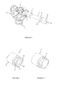
- FIG. 5 and 6 a perspective view of crushing device (4) comprising crushing member (42) is given.
- the crushing member (42) relating to the assembly method which is the subject of the invention comprises a body (41), circular crushing members (42) located on the slots (43) created on said body, a retaining cover (44) that provides fixing of these crushing members (42) onto said body (41). By means of this cover (44), easy replacement of circular crushing members (42) is provided in probable deformation cases.
- Said circular crushing members (42) are at least two in number, in a way to be axially symmetrical to one another and on the same plane. Therefore, the number of the slots (43) formed on the body (41) of the device (4) is at least two as well. Number of the slots (43) formed on the device' body (41) can be increased and crushing members (42) can be placed on some of the slots (43) thereof. Crushing operation can be performed by placing only certain crushing members (42) as well.
- Said circular crushing members (42) have been selected preferably as balls for this application of the invention, they can be any material having a roller or any other circular form strong enough in structure to be capable of carrying out crushing process. While dimensions/sizes of said crushing members (42) can vary according to desired crushing form, crushing members (42) of different sizes can be used on the same body (41).
- the crushing device (4) which is the subject of the invention, as seen in Figure 4 and Figure 5 , is used for assembling ujoint cross (1) piece to a yoke half (2).
- Said ujoint cross (1) has 4 arms (12), these arms (12) insert into the (11) gap inside the mounting hole (21) found in yoke half (2) and into which universal joint bearing (11) is inserted.
- Diameter of the circle which will tangent to the exterior all the crushing members (42) on crushing device (4) must be greater than the diameter of the universal jont bearing mounting hole (21) which will be crushed with said device (4).
- fixing of the universal joint bearing (11) can be achieved by means of the crushing forms (46) formed by crushing of the material in amount of the difference between from the mounting hole wall (210) and crushing members (42) extensions toward the upper surface of the universal joint bearing (11).
- the difference between diameter of the tangent slightly touching exterior of crushing elements (42) and the diameter of the universal joint bearing mounting hole (21) which will be crushed with these members, or diameters of crushing members (42) can be increased, and crushing members (42) crush more material from the mounting hole wall (210) can also be achieved.
- Figure 3 a cross-sectional view relating to assembly operation , on reciprocal arms (22) of the same yoke half done by using the assembly device (5) being used in the prior art and the assembly device (4) which is the subject of the invention is given. While the assembly method in left half of Figure 3 is applied via the stripping device (5) in the prior art, it comprises invention assembly method and device (4) are contained in its right half.
- Reciprocal arms (12) of the ujoint cross (1) are inserted into universal joint bearing mounting holes (21) located on the arms (22) of yoke half (2). Subsequently, universal joint bearings (11) are seated in to the mounting holes (21) in a way contacting interior surface of said universal joint bearing assembly hole (21). Said universal joint bearings (11) are pushed into mounting hole (21) in the direction of M indicated in Figure 2 by means of centring guide bar (3). Thus, said ujoint cross (1) is centred between the arms (22) of yoke half (2).
- crushing device (4) having circular crushing members (42) working on guide shaft (3) applies pressure to mounting hole upper surface (210) found in yoke half (2).
- hole (21) area on universal joint bearing (11) is expanded by crushing.
- Notches and crushing forms (46) formed with this method block exitway of universal joint bearings (11) and does pre-loading onto universal joint bearings (11) in order to provide the ujoint cross (1) to rotate without gap.
- Crushed material advances, upon jamming, expanding towards the gap inside the hole (21).
- this crushing process is applied with sufficient force and distance, it provides compaction of the universal joint bearing (11) in its present position via deformation of the material around the hole (21) towards circumference of the universal joint bearings (11).
Landscapes
- Engineering & Computer Science (AREA)
- General Engineering & Computer Science (AREA)
- Mechanical Engineering (AREA)
- Pivots And Pivotal Connections (AREA)
- Shafts, Cranks, Connecting Bars, And Related Bearings (AREA)
- Crushing And Pulverization Processes (AREA)
- Mounting Of Bearings Or Others (AREA)
Priority Applications (1)
| Application Number | Priority Date | Filing Date | Title |
|---|---|---|---|
| PL12176422T PL2546537T3 (pl) | 2011-07-13 | 2012-07-13 | Wygniatające urządzenie do przegubu Cardana, którym można osiągnąć wygniatanie o zaokrąglonych liniach |
Applications Claiming Priority (1)
| Application Number | Priority Date | Filing Date | Title |
|---|---|---|---|
| TR2011/06952A TR201106952A2 (tr) | 2011-07-13 | 2011-07-13 | Yuvarlatılmış hatlar ile ezme yapabilen kardan mafsalı ezme aparatı. |
Publications (3)
| Publication Number | Publication Date |
|---|---|
| EP2546537A2 true EP2546537A2 (de) | 2013-01-16 |
| EP2546537A3 EP2546537A3 (de) | 2013-10-30 |
| EP2546537B1 EP2546537B1 (de) | 2016-10-12 |
Family
ID=46514196
Family Applications (1)
| Application Number | Title | Priority Date | Filing Date |
|---|---|---|---|
| EP12176422.9A Active EP2546537B1 (de) | 2011-07-13 | 2012-07-13 | Zerkleinerungsvorrichtung für Kardanverbindung, das eine Zerkleinerung mit abgerundeten Linien erreichen kann |
Country Status (4)
| Country | Link |
|---|---|
| EP (1) | EP2546537B1 (de) |
| ES (1) | ES2603156T3 (de) |
| PL (1) | PL2546537T3 (de) |
| TR (1) | TR201106952A2 (de) |
Citations (4)
| Publication number | Priority date | Publication date | Assignee | Title |
|---|---|---|---|---|
| US3217399A (en) | 1963-12-19 | 1965-11-16 | Schaeffler Ohg Industriewerk | Universal joint assembly method and apparatus |
| US3230617A (en) | 1963-08-27 | 1966-01-25 | Schaeffler Ohg Industriewerk | Method and apparatus for assembling universal joints |
| US4162568A (en) | 1976-10-07 | 1979-07-31 | Industriewerk Schaeffler Ohg | Apparatus for universal joint assembly |
| US4704782A (en) | 1985-10-19 | 1987-11-10 | Ina Walzlager Schaeffler Kg | Universal joint assembly method and apparatus |
Family Cites Families (3)
| Publication number | Priority date | Publication date | Assignee | Title |
|---|---|---|---|---|
| JPS55129623A (en) * | 1979-03-26 | 1980-10-07 | Toyota Motor Corp | Fixing method of bearing cup for universal joint |
| JPH05118343A (ja) * | 1991-10-23 | 1993-05-14 | Atsugi Unisia Corp | 自在継手の軸受固定方法 |
| JPH05296256A (ja) * | 1992-04-13 | 1993-11-09 | Unisia Jecs Corp | 自在継手の組立方法ならびに自在継手 |
-
2011
- 2011-07-13 TR TR2011/06952A patent/TR201106952A2/xx unknown
-
2012
- 2012-07-13 PL PL12176422T patent/PL2546537T3/pl unknown
- 2012-07-13 EP EP12176422.9A patent/EP2546537B1/de active Active
- 2012-07-13 ES ES12176422.9T patent/ES2603156T3/es active Active
Patent Citations (4)
| Publication number | Priority date | Publication date | Assignee | Title |
|---|---|---|---|---|
| US3230617A (en) | 1963-08-27 | 1966-01-25 | Schaeffler Ohg Industriewerk | Method and apparatus for assembling universal joints |
| US3217399A (en) | 1963-12-19 | 1965-11-16 | Schaeffler Ohg Industriewerk | Universal joint assembly method and apparatus |
| US4162568A (en) | 1976-10-07 | 1979-07-31 | Industriewerk Schaeffler Ohg | Apparatus for universal joint assembly |
| US4704782A (en) | 1985-10-19 | 1987-11-10 | Ina Walzlager Schaeffler Kg | Universal joint assembly method and apparatus |
Also Published As
| Publication number | Publication date |
|---|---|
| EP2546537B1 (de) | 2016-10-12 |
| EP2546537A3 (de) | 2013-10-30 |
| ES2603156T3 (es) | 2017-02-23 |
| TR201106952A2 (tr) | 2012-08-22 |
| PL2546537T3 (pl) | 2017-04-28 |
Similar Documents
| Publication | Publication Date | Title |
|---|---|---|
| US8646181B2 (en) | Shaft-hub component and method for manufacturing a component of this type | |
| DE102018200865B4 (de) | Rotor für eine elektrische Maschine | |
| KR101727822B1 (ko) | 로터 구조 | |
| CN101008416B (zh) | 卡环锁定夹子和方法 | |
| DE102012204491A1 (de) | Bohrwerkzeug | |
| EP2213894A1 (de) | Wälzlagerkäfig | |
| KR20180042261A (ko) | 선회 베어링 | |
| DE102011101621A1 (de) | Schleifringeinheit | |
| EP3026275B1 (de) | Geteilte kugelgelenkhülse | |
| WO2004011172A1 (de) | Abstreifeinrichtung | |
| JP6514506B2 (ja) | スラストころ軸受の保持器、およびその製造方法 | |
| DE112011105225T5 (de) | Kupplungsausrücklagervorrichtung | |
| EP2546537B1 (de) | Zerkleinerungsvorrichtung für Kardanverbindung, das eine Zerkleinerung mit abgerundeten Linien erreichen kann | |
| WO2014029390A1 (de) | Lager, insbesondere pendelkörperlager | |
| JP4534166B2 (ja) | 車輪保持体にある車輪軸受モジュール | |
| WO2017008796A1 (de) | Magnetisches geberpolrad für einen elektromotor | |
| US8347507B2 (en) | Method for assembling roller bearing | |
| US8371012B2 (en) | Drill press cutter | |
| CN105745460B (zh) | 轴承装置和轴承装置的制造方法 | |
| GB1563935A (en) | Cage | |
| EP1036622B1 (de) | Vorrichtung zum Bruchtrennen eines Bauteiles in zwischen Bauteilbegrenzungen und einer Durchbrechung vorgesehenen Querschnitten, insbesondere einer geteilten Lageranordnung | |
| EP2923096B1 (de) | Lagerschale mit ausrichtungsprojektionsmerkmal | |
| EP2730794A2 (de) | Zentrierballstruktur zum Selbstzentrieren doppelter Kardangelenke | |
| JP2009185983A (ja) | 金属保持器 | |
| EP3770453B1 (de) | Wälzlagerkäfig |
Legal Events
| Date | Code | Title | Description |
|---|---|---|---|
| PUAI | Public reference made under article 153(3) epc to a published international application that has entered the european phase |
Free format text: ORIGINAL CODE: 0009012 |
|
| AK | Designated contracting states |
Kind code of ref document: A2 Designated state(s): AL AT BE BG CH CY CZ DE DK EE ES FI FR GB GR HR HU IE IS IT LI LT LU LV MC MK MT NL NO PL PT RO RS SE SI SK SM TR |
|
| AX | Request for extension of the european patent |
Extension state: BA ME |
|
| PUAL | Search report despatched |
Free format text: ORIGINAL CODE: 0009013 |
|
| AK | Designated contracting states |
Kind code of ref document: A3 Designated state(s): AL AT BE BG CH CY CZ DE DK EE ES FI FR GB GR HR HU IE IS IT LI LT LU LV MC MK MT NL NO PL PT RO RS SE SI SK SM TR |
|
| AX | Request for extension of the european patent |
Extension state: BA ME |
|
| RIC1 | Information provided on ipc code assigned before grant |
Ipc: F16D 3/40 20060101AFI20130923BHEP |
|
| 17P | Request for examination filed |
Effective date: 20140319 |
|
| 17Q | First examination report despatched |
Effective date: 20150305 |
|
| RAP1 | Party data changed (applicant data changed or rights of an application transferred) |
Owner name: TIRSAN KARDAN SANAYI VE TICARET ANONIM SIRKETI |
|
| GRAP | Despatch of communication of intention to grant a patent |
Free format text: ORIGINAL CODE: EPIDOSNIGR1 |
|
| INTG | Intention to grant announced |
Effective date: 20160714 |
|
| GRAS | Grant fee paid |
Free format text: ORIGINAL CODE: EPIDOSNIGR3 |
|
| GRAA | (expected) grant |
Free format text: ORIGINAL CODE: 0009210 |
|
| AK | Designated contracting states |
Kind code of ref document: B1 Designated state(s): AL AT BE BG CH CY CZ DE DK EE ES FI FR GB GR HR HU IE IS IT LI LT LU LV MC MK MT NL NO PL PT RO RS SE SI SK SM TR |
|
| REG | Reference to a national code |
Ref country code: GB Ref legal event code: FG4D |
|
| REG | Reference to a national code |
Ref country code: CH Ref legal event code: EP |
|
| REG | Reference to a national code |
Ref country code: AT Ref legal event code: REF Ref document number: 836814 Country of ref document: AT Kind code of ref document: T Effective date: 20161015 |
|
| REG | Reference to a national code |
Ref country code: IE Ref legal event code: FG4D |
|
| REG | Reference to a national code |
Ref country code: NL Ref legal event code: FP |
|
| REG | Reference to a national code |
Ref country code: DE Ref legal event code: R096 Ref document number: 602012023961 Country of ref document: DE |
|
| REG | Reference to a national code |
Ref country code: SE Ref legal event code: TRGR |
|
| REG | Reference to a national code |
Ref country code: LT Ref legal event code: MG4D |
|
| REG | Reference to a national code |
Ref country code: ES Ref legal event code: FG2A Ref document number: 2603156 Country of ref document: ES Kind code of ref document: T3 Effective date: 20170223 |
|
| PG25 | Lapsed in a contracting state [announced via postgrant information from national office to epo] |
Ref country code: LV Free format text: LAPSE BECAUSE OF FAILURE TO SUBMIT A TRANSLATION OF THE DESCRIPTION OR TO PAY THE FEE WITHIN THE PRESCRIBED TIME-LIMIT Effective date: 20161012 |
|
| REG | Reference to a national code |
Ref country code: AT Ref legal event code: MK05 Ref document number: 836814 Country of ref document: AT Kind code of ref document: T Effective date: 20161012 |
|
| PG25 | Lapsed in a contracting state [announced via postgrant information from national office to epo] |
Ref country code: GR Free format text: LAPSE BECAUSE OF FAILURE TO SUBMIT A TRANSLATION OF THE DESCRIPTION OR TO PAY THE FEE WITHIN THE PRESCRIBED TIME-LIMIT Effective date: 20170113 Ref country code: LT Free format text: LAPSE BECAUSE OF FAILURE TO SUBMIT A TRANSLATION OF THE DESCRIPTION OR TO PAY THE FEE WITHIN THE PRESCRIBED TIME-LIMIT Effective date: 20161012 Ref country code: NO Free format text: LAPSE BECAUSE OF FAILURE TO SUBMIT A TRANSLATION OF THE DESCRIPTION OR TO PAY THE FEE WITHIN THE PRESCRIBED TIME-LIMIT Effective date: 20170112 |
|
| PG25 | Lapsed in a contracting state [announced via postgrant information from national office to epo] |
Ref country code: AT Free format text: LAPSE BECAUSE OF FAILURE TO SUBMIT A TRANSLATION OF THE DESCRIPTION OR TO PAY THE FEE WITHIN THE PRESCRIBED TIME-LIMIT Effective date: 20161012 Ref country code: IS Free format text: LAPSE BECAUSE OF FAILURE TO SUBMIT A TRANSLATION OF THE DESCRIPTION OR TO PAY THE FEE WITHIN THE PRESCRIBED TIME-LIMIT Effective date: 20170212 Ref country code: BE Free format text: LAPSE BECAUSE OF FAILURE TO SUBMIT A TRANSLATION OF THE DESCRIPTION OR TO PAY THE FEE WITHIN THE PRESCRIBED TIME-LIMIT Effective date: 20161012 Ref country code: FI Free format text: LAPSE BECAUSE OF FAILURE TO SUBMIT A TRANSLATION OF THE DESCRIPTION OR TO PAY THE FEE WITHIN THE PRESCRIBED TIME-LIMIT Effective date: 20161012 Ref country code: RS Free format text: LAPSE BECAUSE OF FAILURE TO SUBMIT A TRANSLATION OF THE DESCRIPTION OR TO PAY THE FEE WITHIN THE PRESCRIBED TIME-LIMIT Effective date: 20161012 Ref country code: HR Free format text: LAPSE BECAUSE OF FAILURE TO SUBMIT A TRANSLATION OF THE DESCRIPTION OR TO PAY THE FEE WITHIN THE PRESCRIBED TIME-LIMIT Effective date: 20161012 Ref country code: PT Free format text: LAPSE BECAUSE OF FAILURE TO SUBMIT A TRANSLATION OF THE DESCRIPTION OR TO PAY THE FEE WITHIN THE PRESCRIBED TIME-LIMIT Effective date: 20170213 |
|
| REG | Reference to a national code |
Ref country code: DE Ref legal event code: R097 Ref document number: 602012023961 Country of ref document: DE |
|
| PG25 | Lapsed in a contracting state [announced via postgrant information from national office to epo] |
Ref country code: RO Free format text: LAPSE BECAUSE OF FAILURE TO SUBMIT A TRANSLATION OF THE DESCRIPTION OR TO PAY THE FEE WITHIN THE PRESCRIBED TIME-LIMIT Effective date: 20161012 Ref country code: EE Free format text: LAPSE BECAUSE OF FAILURE TO SUBMIT A TRANSLATION OF THE DESCRIPTION OR TO PAY THE FEE WITHIN THE PRESCRIBED TIME-LIMIT Effective date: 20161012 Ref country code: SK Free format text: LAPSE BECAUSE OF FAILURE TO SUBMIT A TRANSLATION OF THE DESCRIPTION OR TO PAY THE FEE WITHIN THE PRESCRIBED TIME-LIMIT Effective date: 20161012 Ref country code: DK Free format text: LAPSE BECAUSE OF FAILURE TO SUBMIT A TRANSLATION OF THE DESCRIPTION OR TO PAY THE FEE WITHIN THE PRESCRIBED TIME-LIMIT Effective date: 20161012 Ref country code: CZ Free format text: LAPSE BECAUSE OF FAILURE TO SUBMIT A TRANSLATION OF THE DESCRIPTION OR TO PAY THE FEE WITHIN THE PRESCRIBED TIME-LIMIT Effective date: 20161012 |
|
| REG | Reference to a national code |
Ref country code: FR Ref legal event code: PLFP Year of fee payment: 6 |
|
| PLBE | No opposition filed within time limit |
Free format text: ORIGINAL CODE: 0009261 |
|
| STAA | Information on the status of an ep patent application or granted ep patent |
Free format text: STATUS: NO OPPOSITION FILED WITHIN TIME LIMIT |
|
| PG25 | Lapsed in a contracting state [announced via postgrant information from national office to epo] |
Ref country code: BG Free format text: LAPSE BECAUSE OF FAILURE TO SUBMIT A TRANSLATION OF THE DESCRIPTION OR TO PAY THE FEE WITHIN THE PRESCRIBED TIME-LIMIT Effective date: 20170112 Ref country code: SM Free format text: LAPSE BECAUSE OF FAILURE TO SUBMIT A TRANSLATION OF THE DESCRIPTION OR TO PAY THE FEE WITHIN THE PRESCRIBED TIME-LIMIT Effective date: 20161012 |
|
| 26N | No opposition filed |
Effective date: 20170713 |
|
| PG25 | Lapsed in a contracting state [announced via postgrant information from national office to epo] |
Ref country code: SI Free format text: LAPSE BECAUSE OF FAILURE TO SUBMIT A TRANSLATION OF THE DESCRIPTION OR TO PAY THE FEE WITHIN THE PRESCRIBED TIME-LIMIT Effective date: 20161012 |
|
| REG | Reference to a national code |
Ref country code: CH Ref legal event code: PL |
|
| REG | Reference to a national code |
Ref country code: IE Ref legal event code: MM4A |
|
| PG25 | Lapsed in a contracting state [announced via postgrant information from national office to epo] |
Ref country code: IE Free format text: LAPSE BECAUSE OF NON-PAYMENT OF DUE FEES Effective date: 20170713 Ref country code: LI Free format text: LAPSE BECAUSE OF NON-PAYMENT OF DUE FEES Effective date: 20170731 Ref country code: CH Free format text: LAPSE BECAUSE OF NON-PAYMENT OF DUE FEES Effective date: 20170731 |
|
| PG25 | Lapsed in a contracting state [announced via postgrant information from national office to epo] |
Ref country code: LU Free format text: LAPSE BECAUSE OF NON-PAYMENT OF DUE FEES Effective date: 20170713 |
|
| REG | Reference to a national code |
Ref country code: FR Ref legal event code: PLFP Year of fee payment: 7 |
|
| PGFP | Annual fee paid to national office [announced via postgrant information from national office to epo] |
Ref country code: PL Payment date: 20180626 Year of fee payment: 7 |
|
| PG25 | Lapsed in a contracting state [announced via postgrant information from national office to epo] |
Ref country code: MT Free format text: LAPSE BECAUSE OF NON-PAYMENT OF DUE FEES Effective date: 20170713 |
|
| PGFP | Annual fee paid to national office [announced via postgrant information from national office to epo] |
Ref country code: DE Payment date: 20180710 Year of fee payment: 7 Ref country code: FR Payment date: 20180731 Year of fee payment: 7 Ref country code: IT Payment date: 20180713 Year of fee payment: 7 Ref country code: ES Payment date: 20180830 Year of fee payment: 7 Ref country code: NL Payment date: 20180712 Year of fee payment: 7 |
|
| PGFP | Annual fee paid to national office [announced via postgrant information from national office to epo] |
Ref country code: GB Payment date: 20180718 Year of fee payment: 7 Ref country code: SE Payment date: 20180716 Year of fee payment: 7 |
|
| PG25 | Lapsed in a contracting state [announced via postgrant information from national office to epo] |
Ref country code: HU Free format text: LAPSE BECAUSE OF FAILURE TO SUBMIT A TRANSLATION OF THE DESCRIPTION OR TO PAY THE FEE WITHIN THE PRESCRIBED TIME-LIMIT; INVALID AB INITIO Effective date: 20120713 Ref country code: MC Free format text: LAPSE BECAUSE OF FAILURE TO SUBMIT A TRANSLATION OF THE DESCRIPTION OR TO PAY THE FEE WITHIN THE PRESCRIBED TIME-LIMIT Effective date: 20161012 |
|
| PG25 | Lapsed in a contracting state [announced via postgrant information from national office to epo] |
Ref country code: CY Free format text: LAPSE BECAUSE OF NON-PAYMENT OF DUE FEES Effective date: 20161012 |
|
| PG25 | Lapsed in a contracting state [announced via postgrant information from national office to epo] |
Ref country code: MK Free format text: LAPSE BECAUSE OF FAILURE TO SUBMIT A TRANSLATION OF THE DESCRIPTION OR TO PAY THE FEE WITHIN THE PRESCRIBED TIME-LIMIT Effective date: 20161012 |
|
| REG | Reference to a national code |
Ref country code: DE Ref legal event code: R119 Ref document number: 602012023961 Country of ref document: DE |
|
| REG | Reference to a national code |
Ref country code: SE Ref legal event code: EUG |
|
| GBPC | Gb: european patent ceased through non-payment of renewal fee |
Effective date: 20190713 |
|
| PG25 | Lapsed in a contracting state [announced via postgrant information from national office to epo] |
Ref country code: GB Free format text: LAPSE BECAUSE OF NON-PAYMENT OF DUE FEES Effective date: 20190713 Ref country code: NL Free format text: LAPSE BECAUSE OF NON-PAYMENT OF DUE FEES Effective date: 20190801 Ref country code: DE Free format text: LAPSE BECAUSE OF NON-PAYMENT OF DUE FEES Effective date: 20200201 Ref country code: SE Free format text: LAPSE BECAUSE OF NON-PAYMENT OF DUE FEES Effective date: 20190714 |
|
| REG | Reference to a national code |
Ref country code: NL Ref legal event code: MM Effective date: 20190801 |
|
| PG25 | Lapsed in a contracting state [announced via postgrant information from national office to epo] |
Ref country code: FR Free format text: LAPSE BECAUSE OF NON-PAYMENT OF DUE FEES Effective date: 20190731 |
|
| PG25 | Lapsed in a contracting state [announced via postgrant information from national office to epo] |
Ref country code: AL Free format text: LAPSE BECAUSE OF FAILURE TO SUBMIT A TRANSLATION OF THE DESCRIPTION OR TO PAY THE FEE WITHIN THE PRESCRIBED TIME-LIMIT Effective date: 20161012 |
|
| PG25 | Lapsed in a contracting state [announced via postgrant information from national office to epo] |
Ref country code: IT Free format text: LAPSE BECAUSE OF NON-PAYMENT OF DUE FEES Effective date: 20190713 |
|
| REG | Reference to a national code |
Ref country code: ES Ref legal event code: FD2A Effective date: 20201126 |
|
| PG25 | Lapsed in a contracting state [announced via postgrant information from national office to epo] |
Ref country code: ES Free format text: LAPSE BECAUSE OF NON-PAYMENT OF DUE FEES Effective date: 20190714 |
|
| PG25 | Lapsed in a contracting state [announced via postgrant information from national office to epo] |
Ref country code: PL Free format text: LAPSE BECAUSE OF NON-PAYMENT OF DUE FEES Effective date: 20190713 |
|
| PGFP | Annual fee paid to national office [announced via postgrant information from national office to epo] |
Ref country code: TR Payment date: 20250709 Year of fee payment: 14 |