EP2546559A1 - Soupape-navette de non-retour soudable à haute température et à haute pression - Google Patents
Soupape-navette de non-retour soudable à haute température et à haute pression Download PDFInfo
- Publication number
- EP2546559A1 EP2546559A1 EP11752800A EP11752800A EP2546559A1 EP 2546559 A1 EP2546559 A1 EP 2546559A1 EP 11752800 A EP11752800 A EP 11752800A EP 11752800 A EP11752800 A EP 11752800A EP 2546559 A1 EP2546559 A1 EP 2546559A1
- Authority
- EP
- European Patent Office
- Prior art keywords
- valve
- upper cover
- manhole
- sleeve
- circular ring
- Prior art date
- Legal status (The legal status is an assumption and is not a legal conclusion. Google has not performed a legal analysis and makes no representation as to the accuracy of the status listed.)
- Granted
Links
- 238000003466 welding Methods 0.000 claims abstract description 4
- 230000004323 axial length Effects 0.000 claims description 2
- 238000009825 accumulation Methods 0.000 abstract description 3
- 238000012423 maintenance Methods 0.000 description 3
- 238000005299 abrasion Methods 0.000 description 1
- 230000009286 beneficial effect Effects 0.000 description 1
- 238000005265 energy consumption Methods 0.000 description 1
- 230000001747 exhibiting effect Effects 0.000 description 1
- 239000012530 fluid Substances 0.000 description 1
- 238000007665 sagging Methods 0.000 description 1
- 238000007789 sealing Methods 0.000 description 1
Images
Classifications
-
- F—MECHANICAL ENGINEERING; LIGHTING; HEATING; WEAPONS; BLASTING
- F16—ENGINEERING ELEMENTS AND UNITS; GENERAL MEASURES FOR PRODUCING AND MAINTAINING EFFECTIVE FUNCTIONING OF MACHINES OR INSTALLATIONS; THERMAL INSULATION IN GENERAL
- F16K—VALVES; TAPS; COCKS; ACTUATING-FLOATS; DEVICES FOR VENTING OR AERATING
- F16K15/00—Check valves
- F16K15/02—Check valves with guided rigid valve members
- F16K15/06—Check valves with guided rigid valve members with guided stems
- F16K15/063—Check valves with guided rigid valve members with guided stems the valve being loaded by a spring
-
- F—MECHANICAL ENGINEERING; LIGHTING; HEATING; WEAPONS; BLASTING
- F16—ENGINEERING ELEMENTS AND UNITS; GENERAL MEASURES FOR PRODUCING AND MAINTAINING EFFECTIVE FUNCTIONING OF MACHINES OR INSTALLATIONS; THERMAL INSULATION IN GENERAL
- F16K—VALVES; TAPS; COCKS; ACTUATING-FLOATS; DEVICES FOR VENTING OR AERATING
- F16K27/00—Construction of housing; Use of materials therefor
- F16K27/02—Construction of housing; Use of materials therefor of lift valves
- F16K27/0209—Check valves or pivoted valves
Definitions
- the present invention relates to a check valve on the high-temperature and high-pressure medium passageway, and in particular to a welded type check valve.
- the existing welded type check valves are swing check valves; closing and opening of the valve flap is a movement centering the lug and cutting the main flow channel.
- the manhole cannot be separated from the main flow channel, thereby resulting in a stagnation zone, swirl, block of filth and concentration of temperature stress, and therefore increase in flow resistance and energy consumption; the lug is displaced due to abrasion and the valve flap strikes the valve seat to cause vibration; leakage of special mediums such as high-temperature and high-pressure fluids will results in safety accident.
- the check valve cannot be mounted at any angle and can only be applied to limited environment.
- the objective of the present invention is to provide a shuttle-typed high temperature and high-pressure welded type check valve which can be conveniently assembled or disassembled, whose components precisely and firmly are positioned therein, and which has the advantages of small flow resistance, incapability of filth accumulation and being mountable at any angle.
- the present invention is carried out in such a manner:
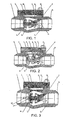
- a shuttle-typed high-temperature and high-pressure welded type check valve of the present invention is provided, wherein a valve seat 6 and a valve sleeve 2 are provided in a valve chamber between two axial ports of a valve body 1; the rear end of the valve sleeve 2 is connected with a circular ring 16 by a support 20; the circular ring 16 is in movable engagement or in thread connection with an inner circle of a flow channel of the valve body port; the front end surface of the valve sleeve 2 is provided with an annular groove; the valve sleeve 2 has a center hole which is in movable engagement with a valve shaft 5 of a valve flap 3; in the annular groove a spring 4 is nested on the valve sleeve and the valve shaft and connected with the valve flap; the valve body is provided with a manhole 10, whose axis is perpendicular to the axial direction of the valve body; a step provided in the manhole is connected with an upper cover 11, whose the lower
- the front end of the circular ring 16 is connected with the front end step of the flow channel and the rear end of the circular ring is connected with an elastic locking ring 9 in the groove of the flow channel.
- a square block or a cylindrical block 7 is connected with the upper cover 11 and the lower end of the block is connected with the valve sleeve 2; a locking nut or pin 8 is passed through the upper cover, the square block or the cylindrical block to connect with the valve sleeve 2.
- One port of the valve chamber is provided with a front support 17 which is integral with the port or is connected with the port via the threads of a circular ring 15 whose end surface is configured as a valve seat; the center hole of the front support is coaxial with the valve body and the valve flap 3 has a front shaft 19 in movable engagement with the center hole of the front support.
- the manhole 10 is circular or square and has an axial length equal to the length from the valve seat 6 to the circular ring 16.
- the present invention has a simple structure.
- the manhole is provided with an upper cover which is completely aligned with the curve face of the main flow channel to separate the chamber of the manhole from the main flow channel, thereby reducing flow resistance and swirl, accumulation of filth and preventing leaking.
- the check valve can be mounted at any angle with the components therein being precisely positioned, and can be conveniently assembled or disassembled; the valve flap and the valve seat can be removed and combined in a free space such that the check valve is safe and reliable in use.
- the two axial ports of the valve body 1 respectively have a circle of welding bevel 14.
- a valve seat 6 for engaging with a valve flap 3 in a sealing manner is provided at one end of the valve chamber and another end of the valve chamber is provided with a valve sleeve 2 which is connected with a circular ring 16 via a support 20; the front end of the circular ring 16 is positioned by a step on the flow channel and the rear end thereof is connected with an elastic locking ring 15 in the groove of the flow channel.
- An annular groove 18 is provided at the front end of the valve sleeve 2 and the valve shaft 5 is engaged with the center hole of the valve sleeve 2 and has a spring 4 thereon.
- a step on the manhole 10 is connected with an upper cover 11 whose underside forms a portion of a symmetrical flow channel of the valve chamber.
- Axial positioning of the valve sleeve is achieved by the elastic locking ring 15 and a step on the inner hole of the flow channel; the circular ring 16 of the valve sleeve is in movable engagement with the inner circle of the flow channel to achieve radial positioning of the valve sleeve; the valve flap can be removed from the manhole for maintenance and can be conveniently disassembled or assembled.
- the elastic locking ring has enough section to bear shear of the axial pushing force and is suitable for valves of middle and small caliber.
- the circular ring 15 of the front support 17 is in thread engagement with the inner circle of the flow channel of the valve body; the valve seat 6 is located on the circular ring 15 of the front support 17; the valve flap has a front shaft 19 in movable engagement with the center hole of the front support; other structures are the same as in the first embodiment.
- the front support 17 can prevent the valve flap from sagging due to weight and has excellent coaxiality, which is beneficial for axial movement of the valve seat and the valve flap during opening or closing.
- the front support is suitable for valves of middle and large caliber. The valve flap, valve seat and front support can be removed for the purpose of maintenance.
- the short edge of a rectangular block 7 is parallel with the axis of the valve body and its long edge is perpendicular to the axis of the valve body, and its lower end is embedded into the rectangular hole of the conical body of the valve sleeve, the hole bottom surface being parallel with the axis of the valve body; the upper end of the block is embedded into the rectangular hole of the upper cover, the hole top surface being parallel with the axis of the valve body.
- the upper cover, the rectangular block and the conical body of the valve sleeve are coupled by the positioning pin or bolt, thereby exhibiting better integrity and rigidity.
- valve sleeve The axial positioning of the valve sleeve is achieved by the rectangular block; the circular ring 16 of the valve sleeve is in movable engagement with the inner circle of the flow channel of the valve body to achieve radial positioning.
- the valve flap and the rectangular block can be removed for maintenance in a free space and are suitable for valves of middle and small caliber.
Landscapes
- Engineering & Computer Science (AREA)
- General Engineering & Computer Science (AREA)
- Mechanical Engineering (AREA)
- Check Valves (AREA)
- Valve Housings (AREA)
- Details Of Valves (AREA)
Applications Claiming Priority (2)
| Application Number | Priority Date | Filing Date | Title |
|---|---|---|---|
| CN2010101233570A CN101776168B (zh) | 2010-03-12 | 2010-03-12 | 梭式高温高压焊接止回阀 |
| PCT/CN2011/000403 WO2011110057A1 (fr) | 2010-03-12 | 2011-03-14 | Soupape-navette de non-retour soudable à haute température et à haute pression |
Publications (3)
| Publication Number | Publication Date |
|---|---|
| EP2546559A1 true EP2546559A1 (fr) | 2013-01-16 |
| EP2546559A4 EP2546559A4 (fr) | 2015-08-12 |
| EP2546559B1 EP2546559B1 (fr) | 2017-05-03 |
Family
ID=42512708
Family Applications (1)
| Application Number | Title | Priority Date | Filing Date |
|---|---|---|---|
| EP11752800.0A Not-in-force EP2546559B1 (fr) | 2010-03-12 | 2011-03-14 | Soupape-navette de non-retour soudable à haute température et à haute pression |
Country Status (3)
| Country | Link |
|---|---|
| EP (1) | EP2546559B1 (fr) |
| CN (1) | CN101776168B (fr) |
| WO (1) | WO2011110057A1 (fr) |
Cited By (2)
| Publication number | Priority date | Publication date | Assignee | Title |
|---|---|---|---|---|
| CN109958799A (zh) * | 2017-12-25 | 2019-07-02 | 重庆昂宇自控仪表有限公司 | 一种轴流式止回阀 |
| US11976747B2 (en) | 2019-03-20 | 2024-05-07 | Danfoss A/S | Compressor unit with a damped axial check valve for a discharge outlet |
Families Citing this family (4)
| Publication number | Priority date | Publication date | Assignee | Title |
|---|---|---|---|---|
| CN101776168B (zh) * | 2010-03-12 | 2011-11-23 | 曾祥炜 | 梭式高温高压焊接止回阀 |
| CN105864469B (zh) * | 2016-04-26 | 2019-02-05 | 苏州纽威阀门股份有限公司 | 一种可在线更换内件的轴流式止回阀 |
| CN110043699A (zh) * | 2018-01-16 | 2019-07-23 | 宝山钢铁股份有限公司 | 超高压单向阀装置 |
| CN111594646A (zh) * | 2020-06-04 | 2020-08-28 | 温州华强法兰有限公司 | 具有双向定位结构的对夹式止回阀 |
Family Cites Families (12)
| Publication number | Priority date | Publication date | Assignee | Title |
|---|---|---|---|---|
| US3106220A (en) * | 1961-09-13 | 1963-10-08 | Atwood & Morrill Co Inc | Check valve, with dashpot |
| US3995658A (en) * | 1974-06-12 | 1976-12-07 | Societe Des Clapets T.J., Socla | Non-return valve |
| US4281680A (en) * | 1979-08-17 | 1981-08-04 | Grove Valve And Regulator Company | Swing check valve construction |
| US4930539A (en) * | 1983-09-22 | 1990-06-05 | 501 Ocean B.V. | Anti-fluttering check valve |
| DE4302666A1 (de) * | 1993-01-30 | 1994-08-04 | Abb Management Ag | Schnellschlussklappe |
| DE19640782A1 (de) * | 1996-10-02 | 1998-04-09 | Bosch Gmbh Robert | Ventil und Verfahren zur Herstellung eines Ventiles |
| DE19854308A1 (de) * | 1998-11-25 | 2000-05-31 | Bosch Gmbh Robert | Ventil |
| CN101220878B (zh) * | 2007-12-14 | 2010-12-22 | 曾祥炜 | 梭式微阻止回阀 |
| CN101220876B (zh) * | 2007-12-14 | 2014-01-15 | 曾祥炜 | 梭式止回阀 |
| CN101614292B (zh) * | 2009-07-21 | 2011-05-18 | 武汉大禹阀门制造有限公司 | 倒流防止器 |
| CN201687996U (zh) * | 2010-03-12 | 2010-12-29 | 曾祥炜 | 梭式高温高压焊接止回阀 |
| CN101776168B (zh) * | 2010-03-12 | 2011-11-23 | 曾祥炜 | 梭式高温高压焊接止回阀 |
-
2010
- 2010-03-12 CN CN2010101233570A patent/CN101776168B/zh not_active Expired - Fee Related
-
2011
- 2011-03-14 WO PCT/CN2011/000403 patent/WO2011110057A1/fr not_active Ceased
- 2011-03-14 EP EP11752800.0A patent/EP2546559B1/fr not_active Not-in-force
Non-Patent Citations (1)
| Title |
|---|
| See references of WO2011110057A1 * |
Cited By (3)
| Publication number | Priority date | Publication date | Assignee | Title |
|---|---|---|---|---|
| CN109958799A (zh) * | 2017-12-25 | 2019-07-02 | 重庆昂宇自控仪表有限公司 | 一种轴流式止回阀 |
| US11976747B2 (en) | 2019-03-20 | 2024-05-07 | Danfoss A/S | Compressor unit with a damped axial check valve for a discharge outlet |
| US12467555B2 (en) | 2019-03-20 | 2025-11-11 | Danfoss A/S | Check valve damping |
Also Published As
| Publication number | Publication date |
|---|---|
| WO2011110057A1 (fr) | 2011-09-15 |
| CN101776168B (zh) | 2011-11-23 |
| EP2546559A4 (fr) | 2015-08-12 |
| EP2546559B1 (fr) | 2017-05-03 |
| CN101776168A (zh) | 2010-07-14 |
Similar Documents
| Publication | Publication Date | Title |
|---|---|---|
| EP2546559A1 (fr) | Soupape-navette de non-retour soudable à haute température et à haute pression | |
| CN206592212U (zh) | 一种活门封油结构及具有其的飞机发动机放油装置 | |
| CN103062419A (zh) | 锻钢制冷阀门 | |
| US20150276065A1 (en) | Cage valve | |
| CN110657258B (zh) | 一种旋塞阀的改进方法及结构 | |
| CN102787871A (zh) | 一种汽轮机主汽阀门 | |
| CN203442472U (zh) | 主蒸汽疏水阀 | |
| CN202691089U (zh) | 柱塞针式节流阀 | |
| CN205423845U (zh) | 一种节流式截止阀 | |
| CN104315155A (zh) | 一种截止阀内旁通结构的改进方法 | |
| EP2817546B1 (fr) | Les surfaces de contact oblique dans un ensemble de soupape | |
| CN102563091A (zh) | 超高压检测截止阀 | |
| CN206398122U (zh) | 一种新型多级降噪v型球阀 | |
| CN203836298U (zh) | 水表接管闸阀 | |
| CN119222338A (zh) | 一种流体控制用截止阀及其工作方法 | |
| CN204004754U (zh) | 低泄漏密封固定球阀 | |
| CN202834138U (zh) | 带平衡孔的平行式闸板阀 | |
| CN202371180U (zh) | 超高压检测截止阀 | |
| CN201723752U (zh) | 多级流量阀 | |
| CN102661396A (zh) | 新型截止阀阀芯连接套机构 | |
| CN202901300U (zh) | 一种抗冲刷截止阀 | |
| CN103398188B (zh) | 一种全通道自密封蝶式球形阀 | |
| CN202768880U (zh) | 一种硬靠背塑胶蝶阀 | |
| CN203258117U (zh) | 两片式立式止回阀 | |
| CN105465401A (zh) | 易于更换阀座的球阀 |
Legal Events
| Date | Code | Title | Description |
|---|---|---|---|
| PUAI | Public reference made under article 153(3) epc to a published international application that has entered the european phase |
Free format text: ORIGINAL CODE: 0009012 |
|
| 17P | Request for examination filed |
Effective date: 20120927 |
|
| AK | Designated contracting states |
Kind code of ref document: A1 Designated state(s): AL AT BE BG CH CY CZ DE DK EE ES FI FR GB GR HR HU IE IS IT LI LT LU LV MC MK MT NL NO PL PT RO RS SE SI SK SM TR |
|
| DAX | Request for extension of the european patent (deleted) | ||
| RAP1 | Party data changed (applicant data changed or rights of an application transferred) |
Owner name: ZENG, XIANGWEI |
|
| RA4 | Supplementary search report drawn up and despatched (corrected) |
Effective date: 20150714 |
|
| RIC1 | Information provided on ipc code assigned before grant |
Ipc: F16K 27/12 20060101ALI20150708BHEP Ipc: F16K 15/06 20060101AFI20150708BHEP Ipc: F16K 27/10 20060101ALI20150708BHEP |
|
| 17Q | First examination report despatched |
Effective date: 20160331 |
|
| GRAP | Despatch of communication of intention to grant a patent |
Free format text: ORIGINAL CODE: EPIDOSNIGR1 |
|
| INTG | Intention to grant announced |
Effective date: 20161110 |
|
| RIN1 | Information on inventor provided before grant (corrected) |
Inventor name: ZENG, XIANGWEI |
|
| RIN1 | Information on inventor provided before grant (corrected) |
Inventor name: ZENG, XIANGWEI |
|
| GRAS | Grant fee paid |
Free format text: ORIGINAL CODE: EPIDOSNIGR3 |
|
| GRAA | (expected) grant |
Free format text: ORIGINAL CODE: 0009210 |
|
| AK | Designated contracting states |
Kind code of ref document: B1 Designated state(s): AL AT BE BG CH CY CZ DE DK EE ES FI FR GB GR HR HU IE IS IT LI LT LU LV MC MK MT NL NO PL PT RO RS SE SI SK SM TR |
|
| REG | Reference to a national code |
Ref country code: GB Ref legal event code: FG4D |
|
| REG | Reference to a national code |
Ref country code: AT Ref legal event code: REF Ref document number: 890369 Country of ref document: AT Kind code of ref document: T Effective date: 20170515 Ref country code: CH Ref legal event code: EP |
|
| REG | Reference to a national code |
Ref country code: IE Ref legal event code: FG4D |
|
| REG | Reference to a national code |
Ref country code: DE Ref legal event code: R096 Ref document number: 602011037583 Country of ref document: DE |
|
| REG | Reference to a national code |
Ref country code: NL Ref legal event code: MP Effective date: 20170503 |
|
| REG | Reference to a national code |
Ref country code: AT Ref legal event code: MK05 Ref document number: 890369 Country of ref document: AT Kind code of ref document: T Effective date: 20170503 |
|
| REG | Reference to a national code |
Ref country code: LT Ref legal event code: MG4D |
|
| PG25 | Lapsed in a contracting state [announced via postgrant information from national office to epo] |
Ref country code: GR Free format text: LAPSE BECAUSE OF FAILURE TO SUBMIT A TRANSLATION OF THE DESCRIPTION OR TO PAY THE FEE WITHIN THE PRESCRIBED TIME-LIMIT Effective date: 20170804 Ref country code: ES Free format text: LAPSE BECAUSE OF FAILURE TO SUBMIT A TRANSLATION OF THE DESCRIPTION OR TO PAY THE FEE WITHIN THE PRESCRIBED TIME-LIMIT Effective date: 20170503 Ref country code: NO Free format text: LAPSE BECAUSE OF FAILURE TO SUBMIT A TRANSLATION OF THE DESCRIPTION OR TO PAY THE FEE WITHIN THE PRESCRIBED TIME-LIMIT Effective date: 20170803 Ref country code: AT Free format text: LAPSE BECAUSE OF FAILURE TO SUBMIT A TRANSLATION OF THE DESCRIPTION OR TO PAY THE FEE WITHIN THE PRESCRIBED TIME-LIMIT Effective date: 20170503 Ref country code: LT Free format text: LAPSE BECAUSE OF FAILURE TO SUBMIT A TRANSLATION OF THE DESCRIPTION OR TO PAY THE FEE WITHIN THE PRESCRIBED TIME-LIMIT Effective date: 20170503 Ref country code: FI Free format text: LAPSE BECAUSE OF FAILURE TO SUBMIT A TRANSLATION OF THE DESCRIPTION OR TO PAY THE FEE WITHIN THE PRESCRIBED TIME-LIMIT Effective date: 20170503 Ref country code: HR Free format text: LAPSE BECAUSE OF FAILURE TO SUBMIT A TRANSLATION OF THE DESCRIPTION OR TO PAY THE FEE WITHIN THE PRESCRIBED TIME-LIMIT Effective date: 20170503 |
|
| PG25 | Lapsed in a contracting state [announced via postgrant information from national office to epo] |
Ref country code: LV Free format text: LAPSE BECAUSE OF FAILURE TO SUBMIT A TRANSLATION OF THE DESCRIPTION OR TO PAY THE FEE WITHIN THE PRESCRIBED TIME-LIMIT Effective date: 20170503 Ref country code: IS Free format text: LAPSE BECAUSE OF FAILURE TO SUBMIT A TRANSLATION OF THE DESCRIPTION OR TO PAY THE FEE WITHIN THE PRESCRIBED TIME-LIMIT Effective date: 20170903 Ref country code: PL Free format text: LAPSE BECAUSE OF FAILURE TO SUBMIT A TRANSLATION OF THE DESCRIPTION OR TO PAY THE FEE WITHIN THE PRESCRIBED TIME-LIMIT Effective date: 20170503 Ref country code: BG Free format text: LAPSE BECAUSE OF FAILURE TO SUBMIT A TRANSLATION OF THE DESCRIPTION OR TO PAY THE FEE WITHIN THE PRESCRIBED TIME-LIMIT Effective date: 20170803 Ref country code: NL Free format text: LAPSE BECAUSE OF FAILURE TO SUBMIT A TRANSLATION OF THE DESCRIPTION OR TO PAY THE FEE WITHIN THE PRESCRIBED TIME-LIMIT Effective date: 20170503 Ref country code: RS Free format text: LAPSE BECAUSE OF FAILURE TO SUBMIT A TRANSLATION OF THE DESCRIPTION OR TO PAY THE FEE WITHIN THE PRESCRIBED TIME-LIMIT Effective date: 20170503 Ref country code: SE Free format text: LAPSE BECAUSE OF FAILURE TO SUBMIT A TRANSLATION OF THE DESCRIPTION OR TO PAY THE FEE WITHIN THE PRESCRIBED TIME-LIMIT Effective date: 20170503 |
|
| PG25 | Lapsed in a contracting state [announced via postgrant information from national office to epo] |
Ref country code: CZ Free format text: LAPSE BECAUSE OF FAILURE TO SUBMIT A TRANSLATION OF THE DESCRIPTION OR TO PAY THE FEE WITHIN THE PRESCRIBED TIME-LIMIT Effective date: 20170503 Ref country code: SK Free format text: LAPSE BECAUSE OF FAILURE TO SUBMIT A TRANSLATION OF THE DESCRIPTION OR TO PAY THE FEE WITHIN THE PRESCRIBED TIME-LIMIT Effective date: 20170503 Ref country code: RO Free format text: LAPSE BECAUSE OF FAILURE TO SUBMIT A TRANSLATION OF THE DESCRIPTION OR TO PAY THE FEE WITHIN THE PRESCRIBED TIME-LIMIT Effective date: 20170503 Ref country code: EE Free format text: LAPSE BECAUSE OF FAILURE TO SUBMIT A TRANSLATION OF THE DESCRIPTION OR TO PAY THE FEE WITHIN THE PRESCRIBED TIME-LIMIT Effective date: 20170503 Ref country code: DK Free format text: LAPSE BECAUSE OF FAILURE TO SUBMIT A TRANSLATION OF THE DESCRIPTION OR TO PAY THE FEE WITHIN THE PRESCRIBED TIME-LIMIT Effective date: 20170503 |
|
| REG | Reference to a national code |
Ref country code: DE Ref legal event code: R097 Ref document number: 602011037583 Country of ref document: DE |
|
| PG25 | Lapsed in a contracting state [announced via postgrant information from national office to epo] |
Ref country code: SM Free format text: LAPSE BECAUSE OF FAILURE TO SUBMIT A TRANSLATION OF THE DESCRIPTION OR TO PAY THE FEE WITHIN THE PRESCRIBED TIME-LIMIT Effective date: 20170503 |
|
| PLBE | No opposition filed within time limit |
Free format text: ORIGINAL CODE: 0009261 |
|
| STAA | Information on the status of an ep patent application or granted ep patent |
Free format text: STATUS: NO OPPOSITION FILED WITHIN TIME LIMIT |
|
| REG | Reference to a national code |
Ref country code: FR Ref legal event code: PLFP Year of fee payment: 8 |
|
| 26N | No opposition filed |
Effective date: 20180206 |
|
| PG25 | Lapsed in a contracting state [announced via postgrant information from national office to epo] |
Ref country code: SI Free format text: LAPSE BECAUSE OF FAILURE TO SUBMIT A TRANSLATION OF THE DESCRIPTION OR TO PAY THE FEE WITHIN THE PRESCRIBED TIME-LIMIT Effective date: 20170503 |
|
| REG | Reference to a national code |
Ref country code: CH Ref legal event code: PL |
|
| GBPC | Gb: european patent ceased through non-payment of renewal fee |
Effective date: 20180314 |
|
| PG25 | Lapsed in a contracting state [announced via postgrant information from national office to epo] |
Ref country code: MC Free format text: LAPSE BECAUSE OF FAILURE TO SUBMIT A TRANSLATION OF THE DESCRIPTION OR TO PAY THE FEE WITHIN THE PRESCRIBED TIME-LIMIT Effective date: 20170503 |
|
| REG | Reference to a national code |
Ref country code: BE Ref legal event code: MM Effective date: 20180331 |
|
| REG | Reference to a national code |
Ref country code: IE Ref legal event code: MM4A |
|
| PG25 | Lapsed in a contracting state [announced via postgrant information from national office to epo] |
Ref country code: LU Free format text: LAPSE BECAUSE OF NON-PAYMENT OF DUE FEES Effective date: 20180314 |
|
| PG25 | Lapsed in a contracting state [announced via postgrant information from national office to epo] |
Ref country code: IE Free format text: LAPSE BECAUSE OF NON-PAYMENT OF DUE FEES Effective date: 20180314 |
|
| PG25 | Lapsed in a contracting state [announced via postgrant information from national office to epo] |
Ref country code: LI Free format text: LAPSE BECAUSE OF NON-PAYMENT OF DUE FEES Effective date: 20180331 Ref country code: CH Free format text: LAPSE BECAUSE OF NON-PAYMENT OF DUE FEES Effective date: 20180331 Ref country code: GB Free format text: LAPSE BECAUSE OF NON-PAYMENT OF DUE FEES Effective date: 20180314 Ref country code: BE Free format text: LAPSE BECAUSE OF NON-PAYMENT OF DUE FEES Effective date: 20180331 |
|
| PG25 | Lapsed in a contracting state [announced via postgrant information from national office to epo] |
Ref country code: MT Free format text: LAPSE BECAUSE OF NON-PAYMENT OF DUE FEES Effective date: 20180314 |
|
| PG25 | Lapsed in a contracting state [announced via postgrant information from national office to epo] |
Ref country code: TR Free format text: LAPSE BECAUSE OF FAILURE TO SUBMIT A TRANSLATION OF THE DESCRIPTION OR TO PAY THE FEE WITHIN THE PRESCRIBED TIME-LIMIT Effective date: 20170503 |
|
| PG25 | Lapsed in a contracting state [announced via postgrant information from national office to epo] |
Ref country code: PT Free format text: LAPSE BECAUSE OF FAILURE TO SUBMIT A TRANSLATION OF THE DESCRIPTION OR TO PAY THE FEE WITHIN THE PRESCRIBED TIME-LIMIT Effective date: 20170503 Ref country code: HU Free format text: LAPSE BECAUSE OF FAILURE TO SUBMIT A TRANSLATION OF THE DESCRIPTION OR TO PAY THE FEE WITHIN THE PRESCRIBED TIME-LIMIT; INVALID AB INITIO Effective date: 20110314 |
|
| PG25 | Lapsed in a contracting state [announced via postgrant information from national office to epo] |
Ref country code: MK Free format text: LAPSE BECAUSE OF NON-PAYMENT OF DUE FEES Effective date: 20170503 Ref country code: CY Free format text: LAPSE BECAUSE OF FAILURE TO SUBMIT A TRANSLATION OF THE DESCRIPTION OR TO PAY THE FEE WITHIN THE PRESCRIBED TIME-LIMIT Effective date: 20170503 |
|
| PG25 | Lapsed in a contracting state [announced via postgrant information from national office to epo] |
Ref country code: AL Free format text: LAPSE BECAUSE OF FAILURE TO SUBMIT A TRANSLATION OF THE DESCRIPTION OR TO PAY THE FEE WITHIN THE PRESCRIBED TIME-LIMIT Effective date: 20170503 |
|
| PGFP | Annual fee paid to national office [announced via postgrant information from national office to epo] |
Ref country code: FR Payment date: 20220330 Year of fee payment: 12 |
|
| PGFP | Annual fee paid to national office [announced via postgrant information from national office to epo] |
Ref country code: IT Payment date: 20220329 Year of fee payment: 12 Ref country code: DE Payment date: 20220406 Year of fee payment: 12 |
|
| REG | Reference to a national code |
Ref country code: DE Ref legal event code: R119 Ref document number: 602011037583 Country of ref document: DE |
|
| PG25 | Lapsed in a contracting state [announced via postgrant information from national office to epo] |
Ref country code: FR Free format text: LAPSE BECAUSE OF NON-PAYMENT OF DUE FEES Effective date: 20230331 Ref country code: DE Free format text: LAPSE BECAUSE OF NON-PAYMENT OF DUE FEES Effective date: 20231003 |
|
| PG25 | Lapsed in a contracting state [announced via postgrant information from national office to epo] |
Ref country code: IT Free format text: LAPSE BECAUSE OF NON-PAYMENT OF DUE FEES Effective date: 20230314 |