EP2546580A2 - Système de ventilation pour l'aération et/ou la purge d'un bâtiment à plusieurs étages contenant plusieurs pièces - Google Patents
Système de ventilation pour l'aération et/ou la purge d'un bâtiment à plusieurs étages contenant plusieurs pièces Download PDFInfo
- Publication number
- EP2546580A2 EP2546580A2 EP12176000A EP12176000A EP2546580A2 EP 2546580 A2 EP2546580 A2 EP 2546580A2 EP 12176000 A EP12176000 A EP 12176000A EP 12176000 A EP12176000 A EP 12176000A EP 2546580 A2 EP2546580 A2 EP 2546580A2
- Authority
- EP
- European Patent Office
- Prior art keywords
- channel
- building
- ventilation
- exhaust
- outside air
- Prior art date
- Legal status (The legal status is an assumption and is not a legal conclusion. Google has not performed a legal analysis and makes no representation as to the accuracy of the status listed.)
- Granted
Links
Images



Classifications
-
- F—MECHANICAL ENGINEERING; LIGHTING; HEATING; WEAPONS; BLASTING
- F24—HEATING; RANGES; VENTILATING
- F24F—AIR-CONDITIONING; AIR-HUMIDIFICATION; VENTILATION; USE OF AIR CURRENTS FOR SCREENING
- F24F12/00—Use of energy recovery systems in air conditioning, ventilation or screening
- F24F12/001—Use of energy recovery systems in air conditioning, ventilation or screening with heat-exchange between supplied and exhausted air
- F24F12/006—Use of energy recovery systems in air conditioning, ventilation or screening with heat-exchange between supplied and exhausted air using an air-to-air heat exchanger
-
- F—MECHANICAL ENGINEERING; LIGHTING; HEATING; WEAPONS; BLASTING
- F24—HEATING; RANGES; VENTILATING
- F24F—AIR-CONDITIONING; AIR-HUMIDIFICATION; VENTILATION; USE OF AIR CURRENTS FOR SCREENING
- F24F12/00—Use of energy recovery systems in air conditioning, ventilation or screening
- F24F12/001—Use of energy recovery systems in air conditioning, ventilation or screening with heat-exchange between supplied and exhausted air
- F24F2012/007—Use of energy recovery systems in air conditioning, ventilation or screening with heat-exchange between supplied and exhausted air using a by-pass for bypassing the heat-exchanger
-
- Y—GENERAL TAGGING OF NEW TECHNOLOGICAL DEVELOPMENTS; GENERAL TAGGING OF CROSS-SECTIONAL TECHNOLOGIES SPANNING OVER SEVERAL SECTIONS OF THE IPC; TECHNICAL SUBJECTS COVERED BY FORMER USPC CROSS-REFERENCE ART COLLECTIONS [XRACs] AND DIGESTS
- Y02—TECHNOLOGIES OR APPLICATIONS FOR MITIGATION OR ADAPTATION AGAINST CLIMATE CHANGE
- Y02B—CLIMATE CHANGE MITIGATION TECHNOLOGIES RELATED TO BUILDINGS, e.g. HOUSING, HOUSE APPLIANCES OR RELATED END-USER APPLICATIONS
- Y02B30/00—Energy efficient heating, ventilation or air conditioning [HVAC]
- Y02B30/56—Heat recovery units
Definitions
- the invention relates to a ventilation system for ventilation of a, in particular multi-storey, multi-room building, with at least two decentralized ventilation units, each room is assigned a decentralized ventilation unit and wherein each ventilation unit connected to the room to be ventilated room side Zu Kunststoffauslass and Having a connected to the room to be ventilated room-side exhaust outlet.
- decentralized ventilation units are used in particular for ventilation of rooms in office buildings or hotels. In contrast to a central ventilation system, there is no need for a sewer system, which must be routed through all floors in particular. Decentralized ventilation units can also be switched on and off easily if, for example, a hotel room is not occupied. Usually, the decentralized ventilation units are used close to facades, so that outside air can be sucked in and exhaust air can be blown out into the environment.
- the supply air fan On the leeward side, the supply air fan must supply outside air in the form of supply air into the room. Therefore, the supply air fan operates on the leeward side against the prevailing negative pressure, so that here too a high fan power connected with a corresponding noise is required.
- the object of the invention is to avoid the aforementioned disadvantages and to provide a ventilation system that ensures efficient ventilation even at high wind loads.
- the ventilation unit has an outside air inlet and an exhaust air outlet, wherein the outside air inlet connected via an outside air duct with the environment of the building and / or the exhaust air outlet is connected via an exhaust duct with the environment of the building, each channel either as a is formed by the building extending channel or alternatively is designed as a at least a part of the building, in particular as a run around the building in the manner of an annular channel, guided channel whose one channel end in the facade area of one side of the building and the other end of the channel in the facade area of another, preferably the opposite side of the building ends.
- each channel extends from one side of the facade to the opposite side of the facade.
- the ventilation devices of two opposite and separated from each other by the hall spaces are preferably connected to a common channel.
- several rooms can be connected to one channel.
- the training offers as an annular channel.
- the annular channel is preferably guided around the outside of the building. Then either the outside air inlets or the exhaust air outlets of the individual ventilation units are connected to the circumferential ring channel.
- the advantages of the invention can be used in any wind direction.
- the ring channel can also be integrated into an intermediate facade for visual reasons.
- a ventilation device can be connected either only to a continuous outside air channel or only to a continuous exhaust air channel or else to a continuous outside air channel and to a continuous exhaust air channel.
- At least one channel can in each case have a non-return flap in the region of at least one channel end, preferably in the region of both channel ends. This allows the channel in question to be closed or opened in the wind, depending on the closing direction of the respective non-return flap.
- a non-return flap is provided in the channel formed as an outer air duct in the region of both channel ends, which allow air from the environment to enter the outer air duct but not allow air to escape from the outer air duct into the environment.
- the non-return flap is pivoted on the windward side due to the wind load in its open position, so that air can enter the outside air duct.
- the check valve on the lee side is in contrast in the closed position.
- a non-return valve may be provided in the channel formed as a discharge air channel in the region of both channel ends, the air from the exhaust air channel leak into the environment but do not allow air from the environment to enter the exhaust air duct.
- the relevant check valve In the area of the windward side, the relevant check valve is in the closed position. In contrast, the leeward check valve is in its open position, so that exhaust air can flow out of the channel.
- one volume flow limiter can be provided in the region of at least one channel end, preferably in the area of both channel ends.
- each ventilation device is assigned directly to a flow restrictor.
- each ventilation device is assigned directly to a flow restrictor.
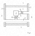
- Fig. 1 a ventilation system for ventilation of a room 1 is shown.
- the space 1 is delimited by two facade areas 2, wherein on both sides of the room 1 further not shown rooms 1 can adjoin.
- a decentralized ventilation unit 3 For ventilation in the room 1, a decentralized ventilation unit 3 is provided.
- the decentralized ventilation device 3 has a not shown, connected to the room to be ventilated 1 or in this room-side Zu Kunststoffauslass 4 and a not shown, connected to the room to be ventilated room-side exhaust outlet 5 5.
- an outside air inlet 6 and an exhaust air outlet 7 is provided, wherein the exhaust air outlet 7 is connected via an exhaust air duct 8 with the environment 9 of the building.
- the exhaust air duct 8 is formed as a channel extending through the building, one end of the channel ends in the facade area 2 of one side of the building and the other end of the channel in the facade area 2 of the opposite side of the building.
- the outside air inlet 6 of the decentralized ventilation device 3 is guided directly through the adjacent facade area 2 into the environment 9. Both in the area of the outside air inlet 6 and in the area of the exhaust air outlet 7, a volume flow limiter 10 is provided in each case.
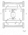
- Fig. 2 an alternative variant is shown.
- the outside air inlet 6 is connected via an outside air duct 11 to the environment 9 of the building, the outside air duct 11 is formed as a channel extending through the building, one channel end in the facade area 2 of one side of the building and the other end of the channel ends in the facade area 2 of the opposite side of the building.
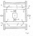
- Fig. 3 illustrates an extended embodiment Fig. 2
- each one check valve 12 is provided with an associated stop 13.
- a wind load 14 hits the right side of the façade.
- the windward check valve 12 is opened in the outer air passage 11, while the leeward check valve 12 is in its closed position.
- the outside air which flows in the direction of the arrow 15, "accumulates" in the outside air duct 11.
- the windward check valve 12 in the exhaust duct 8 is in the illustrated embodiment in the closed position and thus abuts against its stop 13.
- the leeward check valve 12 is in its open position, so that the exhaust air can flow out of the exhaust air duct 8 in the direction of the arrow 16.
- the non-return valve 12 in the exhaust air duct 8 ensures that no air is forced into the exhaust air duct 8.
- the negative pressure supports the blowing out of the exhaust air.
- the maximum pressure increase, which has to promote the provided in the ventilation unit 3 exhaust fan 31 is the direct path from the ventilation unit 3 via the exhaust air duct 8 on the leeward facade area 2 via the check valve 12.
- the exhaust air is blown only on the windward facade area 2, if the Pressure loss is lower over this route.
- Fig. 5 the opposite case is shown.
- the windward check valve 12 is opened in the outer air passage 11, while the leeward check valve 12 abuts against its stop 13.
- the windward check valve 12 is located at its stop 13, while the leeward check valve 12 is in its open position.
- each usage unit consists of two rooms 1.
- the air flows from the room-side Zu Kunststoffauslass 4 of the respective decentralized ventilation unit 3 in the direction of arrow 17 to the corresponding room-side exhaust outlet. 5
- Fig. 6 can be seen, only the exhaust air duct 8 is guided through the building here.
- the outside air duct 11 is not passed through the building. Instead open the outside air inlets 6 of the ventilation units 3 in the rooms 1, which adjoin a common facade area 2, ie lie on one side of the building, in a common outside air duct 11.
- Each outside air duct 11 terminates in the adjacent facade area 2.
- In the facade area is in the Outside air duct 11 next to the non-return valve 12 is still an unillustrated flow restrictor 10 is provided.
- a flow restrictor 10 may be upstream.
- the exhaust air outlets 7 are connected via an exhaust air duct 8 with the environment 9 of the building.
- the exhaust air duct 8 is formed as a channel extending through the building, one end of the channel ends in the facade area 2 of one side of the building and the other end of the channel in the facade area 2 on the other side of the building.
- a check valve 12 is provided in the region of each channel end, i. in the area of each façade area 2 .
- a volume flow limiter 10 is provided in each case.
- the volumetric flow limiter 10 arranged in the outside air duct 11 delimits the quantity flowing over the outside air duct 11 to the set value.
- Each Zuluftventilator 23 only has to overcome the pressure of the subsequent sewer network in the room 1.
- the non-return flap 12 on the leeward side prevents in the outside air duct 11 a sucking out of the air via the outside air duct 11.
- Each supply air fan 23 of the ventilation devices 3 on the leeward side must overcome the here prevailing facade-side negative pressure and the pressure loss via the outside air duct 11. The use of volume flow constant supply air fans 23 is useful in this embodiment.
- Fig. 7 are also the outside air inlets 6 connected via an outside air duct 11 with the environment 9 of the building.
- the outside air duct 11 is formed as a channel extending through the building, one end of the channel terminating in the façade area 2 of one side of the building and the other end of the channel in the façade area 2 on the opposite side of the building.
- a non-return flap 12 with an associated stop 13 is provided in the region of each channel end, ie in the region of each facade region 2.
- a volume flow limiter 10 is provided in the area of each outside air inlet 6.
- Fig. 7 may with respect to the exhaust air on the explanations to the embodiment according to Fig. 6 to get expelled.
- a check valve 12 is provided in each of the two facade areas 2.
- the volume flow limiters 10 are arranged in the region of each outside air inlet 6 of a ventilation device 3.
- the check valve 12 on the leeward side prevents air from being sucked out of the outside air duct 11.
- On the windward side of the flow restrictor 10 limits the flow to the value that is needed to supply the rooms 1.
- Each ventilation unit 3 conveys the set volume flow.
- the amount of air that is not skimmed in the windward space 2 flows to the leeward side of the building and is there via the corresponding ventilation unit 3 in the associated leeward space 1. Since the maximum volume flow that can flow through the outside air duct 11, in the in Fig. 7 illustrated embodiment corresponds to 4 times the volume flow of a room 1, the outside air duct 11 must be designed accordingly.
- the supply air fans 23 When wind pressure is impending on a façade area 2, the supply air fans 23 only have to overcome the pressure loss which builds up behind the volume flow limiter 10 as far as the ventilation device 3. If no wind blows, the supply air fans 23 must additionally overcome the resistance of the outside air duct 11 accordingly. At this operating point, the relevant supply air fan 23 is preferably set.
- the use of volume flow constant supply air fans 23 is in the embodiment after Fig. 7 not required, since the constant volume flow is ensured by the flow restrictor 10. By switching off a ventilation device 3, the remaining area of the outside air duct 11 is not affected.
- the outside air fans 23 be designed constant volume flow, so that they overcome the negative pressure on the lee side of the building at an occurring wind load 14.
- the relevant outside air fan 23 must increase its speed independently.
- all channels, ie all exhaust air ducts 8 and outer air ducts 11 are equipped with at least one silencer, which reduces the noise of the volumetric flow limiter 10.
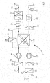
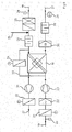
- FIG. 8 and 9 is exemplified a decentralized exhaust air / supply air ventilation unit 3 shown with heat recovery.
- the ventilation device 3 has a heat exchanger 18, which is flowed through by the outside air and the exhaust air in countercurrent.
- an optional outside temperature sensor 20 As seen in the flow direction 19 in front of the heat exchanger 18, an optional outside temperature sensor 20, a motor-operated closure flap 21, a fine dust filter 22 and a supply air fan 23 are provided in the supply air branch.
- a silencer 24, an air heater 25 and an optional supply air temperature sensor 26 connects.
- a VOC sensor 28 As seen in the flow direction 27, a VOC sensor 28, a silencer 29 and a coarse dust filter 30 adjoin the heat exchanger 18 in the exhaust air branch. Behind the heat exchanger 18, an exhaust fan 31 and a motorized shutter 32 is provided.
- a bypass 33 with a motor-operated bypass flap 34 is provided in the Zu Kunststoffzweig to lead outside air, bypassing the heat exchanger 18 can.
- Fig. 9 illustrated embodiment is located in the Zu Kunststoffzweig still a Sekundär Kunststoffeinmischung 35.
- Secondary air is room air, which is not discharged into the environment 9, but to be fed back to the room 2.
- Such a secondary air fan may be dispensed with if the secondary air interference 35 is seen upstream of the supply air fan 23, as seen in the flow direction. for example, between the particulate filter 22 and the supply air fan 23 takes place.
- the filter 22 which is for example an F7 filter, may also be arranged outside the ventilation device 3.
- the filter 22 is arranged in front of the ventilation device 3 in the outside air duct 11.
- an air heater 25 is shown in the outside air duct 11, an air heater 25 is shown. This can of course also be an air cooler.
- the decentralized ventilation device 3 may, for example, also be a pure exhaust air ventilation device, a pure supply air ventilation device or an exhaust air / supply air ventilation device without heat recovery.
- the alternative embodiment in which the outside air duct (11) and / or the exhaust air outlet (7) in each case as a trained around at least a part of the building, in particular as a run around the building in the manner of an annular channel, channel is (are).
- Such a configuration is particularly suitable for buildings with round floor plans.
Landscapes
- Engineering & Computer Science (AREA)
- Chemical & Material Sciences (AREA)
- Combustion & Propulsion (AREA)
- Mechanical Engineering (AREA)
- General Engineering & Computer Science (AREA)
- Ventilation (AREA)
- Building Environments (AREA)
- Duct Arrangements (AREA)
Applications Claiming Priority (1)
| Application Number | Priority Date | Filing Date | Title |
|---|---|---|---|
| DE202011050699U DE202011050699U1 (de) | 2011-07-12 | 2011-07-12 | Lüftungssystem zur Be- und/oder Entlüftung eines, insbesondere mehrgeschossigen, mehrere Räume aufweisenden Gebäudes |
Publications (3)
| Publication Number | Publication Date |
|---|---|
| EP2546580A2 true EP2546580A2 (fr) | 2013-01-16 |
| EP2546580A3 EP2546580A3 (fr) | 2013-11-27 |
| EP2546580B1 EP2546580B1 (fr) | 2017-03-15 |
Family
ID=44860034
Family Applications (1)
| Application Number | Title | Priority Date | Filing Date |
|---|---|---|---|
| EP12176000.3A Not-in-force EP2546580B1 (fr) | 2011-07-12 | 2012-07-11 | Système de ventilation pour l'aération et/ou la purge d'un bâtiment à plusieurs étages contenant plusieurs pièces |
Country Status (2)
| Country | Link |
|---|---|
| EP (1) | EP2546580B1 (fr) |
| DE (1) | DE202011050699U1 (fr) |
Family Cites Families (5)
| Publication number | Priority date | Publication date | Assignee | Title |
|---|---|---|---|---|
| DE4135130C2 (de) * | 1991-10-24 | 1996-07-11 | Schako Metallwarenfabrik | Be- und Entlüftungssystem für Wohnräume in Wohnungen |
| DE4202838A1 (de) * | 1992-01-29 | 1993-08-05 | Horn Wolfgang | Verfahren und einrichtung zum schutz von bauwerken gegen eindringen gefaehrlicher gase, insbesondere von radon aus dem baugrund |
| DE10010832C1 (de) * | 2000-03-09 | 2001-11-22 | Krantz Tkt Gmbh | Vorrichtung zur Temperierung und/oder Belüftung eines Raumes |
| DE20115688U1 (de) * | 2001-09-24 | 2001-12-06 | Gebrüder Trox, GmbH, 47506 Neukirchen-Vluyn | Belüftungssystem zur Raumbelüftung |
| DE10139927A1 (de) * | 2001-08-14 | 2003-02-27 | Conit Lufttechnik Gmbh | Gebäude mit einer Be- und Entlüftungsanlage und Verfahren zur Sanierung derartiger Wohngebäude |
-
2011
- 2011-07-12 DE DE202011050699U patent/DE202011050699U1/de not_active Expired - Lifetime
-
2012
- 2012-07-11 EP EP12176000.3A patent/EP2546580B1/fr not_active Not-in-force
Non-Patent Citations (1)
| Title |
|---|
| None |
Also Published As
| Publication number | Publication date |
|---|---|
| EP2546580A3 (fr) | 2013-11-27 |
| EP2546580B1 (fr) | 2017-03-15 |
| DE202011050699U1 (de) | 2011-09-26 |
Similar Documents
| Publication | Publication Date | Title |
|---|---|---|
| EP1132690B1 (fr) | Dispositif permettant de tempérer et/ou de ventiler une pièce | |
| EP2594725A2 (fr) | Fenêtre | |
| WO2010026049A1 (fr) | Véhicule ferroviaire pouvant être commuté entre un mode hiver et un mode été | |
| EP3120085B1 (fr) | Dispositif de ventilation | |
| DE3224277A1 (de) | Verfahren und waermerueckgewinnungssystem zum regenerativen waermeaustausch | |
| EP2194329B1 (fr) | Appareil de ventilation ainsi que procédé de fonctionnement de l'appareil de ventilation | |
| DE3040739A1 (de) | Anordnung zur abluftwaermerueckgewinnung | |
| EP4232758B1 (fr) | Dispositif d'aération | |
| EP2546580B1 (fr) | Système de ventilation pour l'aération et/ou la purge d'un bâtiment à plusieurs étages contenant plusieurs pièces | |
| DE102011000525A1 (de) | Verfahren zum Betreiben einer Lüftungsanlage mit einer Mischkammer | |
| DE1604296B2 (fr) | ||
| DE60318074T2 (de) | Zentraler staubsauger und seine zentrale einheit | |
| DE20209031U1 (de) | Belüftungssystem zur Raumbe- und -entlüftung | |
| DE102011002605B4 (de) | Dezentrale Raumlüftungsvorrichtung mit Wärmerückgewinnung | |
| WO2018068879A1 (fr) | Aérateur de grands locaux et salles | |
| DE202013102473U1 (de) | Raumlufttechnisches (RLT) Gerät für eine zentrale RLT Anlage | |
| DE202010004933U1 (de) | Wand-Wärmetauscher | |
| DE112020007598T5 (de) | Intelligente Klimaanlage | |
| EP2985545A1 (fr) | Installation dotée d'échangeurs de chaleur à plaques pour déshumidification d'un flux d'air | |
| EP1496318B1 (fr) | Dispositif de sortie d'air pour les plafonds | |
| EP2184557B1 (fr) | Système d'aération | |
| WO1995018944A1 (fr) | Appareil de climatisation a ventilateur redondant | |
| DE202015102781U1 (de) | Lüftungseinrichtung für Reinräume | |
| DE202008016732U1 (de) | Raumlufttechnisches Gerät | |
| DE102024138004A1 (de) | Lüftungsanlage, insbesondere zum Lüften eines Gebäudes, mit verbessertem Brandschutz, Lüftungsgerät und Verschlusseinrichtung für eine solche, sowie Vorrichtung zum Nutzen von Wärme umfassend eine solche Lüftungsanlage |
Legal Events
| Date | Code | Title | Description |
|---|---|---|---|
| PUAI | Public reference made under article 153(3) epc to a published international application that has entered the european phase |
Free format text: ORIGINAL CODE: 0009012 |
|
| AK | Designated contracting states |
Kind code of ref document: A2 Designated state(s): AL AT BE BG CH CY CZ DE DK EE ES FI FR GB GR HR HU IE IS IT LI LT LU LV MC MK MT NL NO PL PT RO RS SE SI SK SM TR |
|
| AX | Request for extension of the european patent |
Extension state: BA ME |
|
| PUAL | Search report despatched |
Free format text: ORIGINAL CODE: 0009013 |
|
| AK | Designated contracting states |
Kind code of ref document: A3 Designated state(s): AL AT BE BG CH CY CZ DE DK EE ES FI FR GB GR HR HU IE IS IT LI LT LU LV MC MK MT NL NO PL PT RO RS SE SI SK SM TR |
|
| AX | Request for extension of the european patent |
Extension state: BA ME |
|
| RIC1 | Information provided on ipc code assigned before grant |
Ipc: F24F 12/00 20060101AFI20131022BHEP |
|
| 17P | Request for examination filed |
Effective date: 20140514 |
|
| RBV | Designated contracting states (corrected) |
Designated state(s): AL AT BE BG CH CY CZ DE DK EE ES FI FR GB GR HR HU IE IS IT LI LT LU LV MC MK MT NL NO PL PT RO RS SE SI SK SM TR |
|
| 17Q | First examination report despatched |
Effective date: 20151007 |
|
| GRAP | Despatch of communication of intention to grant a patent |
Free format text: ORIGINAL CODE: EPIDOSNIGR1 |
|
| INTG | Intention to grant announced |
Effective date: 20161010 |
|
| GRAS | Grant fee paid |
Free format text: ORIGINAL CODE: EPIDOSNIGR3 |
|
| GRAA | (expected) grant |
Free format text: ORIGINAL CODE: 0009210 |
|
| AK | Designated contracting states |
Kind code of ref document: B1 Designated state(s): AL AT BE BG CH CY CZ DE DK EE ES FI FR GB GR HR HU IE IS IT LI LT LU LV MC MK MT NL NO PL PT RO RS SE SI SK SM TR |
|
| REG | Reference to a national code |
Ref country code: CH Ref legal event code: EP Ref country code: GB Ref legal event code: FG4D Free format text: NOT ENGLISH |
|
| REG | Reference to a national code |
Ref country code: IE Ref legal event code: FG4D Free format text: LANGUAGE OF EP DOCUMENT: GERMAN |
|
| REG | Reference to a national code |
Ref country code: AT Ref legal event code: REF Ref document number: 875989 Country of ref document: AT Kind code of ref document: T Effective date: 20170415 |
|
| REG | Reference to a national code |
Ref country code: DE Ref legal event code: R096 Ref document number: 502012009765 Country of ref document: DE |
|
| REG | Reference to a national code |
Ref country code: NL Ref legal event code: FP |
|
| REG | Reference to a national code |
Ref country code: FR Ref legal event code: PLFP Year of fee payment: 6 |
|
| REG | Reference to a national code |
Ref country code: LT Ref legal event code: MG4D |
|
| PG25 | Lapsed in a contracting state [announced via postgrant information from national office to epo] |
Ref country code: NO Free format text: LAPSE BECAUSE OF FAILURE TO SUBMIT A TRANSLATION OF THE DESCRIPTION OR TO PAY THE FEE WITHIN THE PRESCRIBED TIME-LIMIT Effective date: 20170615 Ref country code: GR Free format text: LAPSE BECAUSE OF FAILURE TO SUBMIT A TRANSLATION OF THE DESCRIPTION OR TO PAY THE FEE WITHIN THE PRESCRIBED TIME-LIMIT Effective date: 20170616 Ref country code: HR Free format text: LAPSE BECAUSE OF FAILURE TO SUBMIT A TRANSLATION OF THE DESCRIPTION OR TO PAY THE FEE WITHIN THE PRESCRIBED TIME-LIMIT Effective date: 20170315 Ref country code: FI Free format text: LAPSE BECAUSE OF FAILURE TO SUBMIT A TRANSLATION OF THE DESCRIPTION OR TO PAY THE FEE WITHIN THE PRESCRIBED TIME-LIMIT Effective date: 20170315 Ref country code: LT Free format text: LAPSE BECAUSE OF FAILURE TO SUBMIT A TRANSLATION OF THE DESCRIPTION OR TO PAY THE FEE WITHIN THE PRESCRIBED TIME-LIMIT Effective date: 20170315 |
|
| PG25 | Lapsed in a contracting state [announced via postgrant information from national office to epo] |
Ref country code: RS Free format text: LAPSE BECAUSE OF FAILURE TO SUBMIT A TRANSLATION OF THE DESCRIPTION OR TO PAY THE FEE WITHIN THE PRESCRIBED TIME-LIMIT Effective date: 20170315 Ref country code: BG Free format text: LAPSE BECAUSE OF FAILURE TO SUBMIT A TRANSLATION OF THE DESCRIPTION OR TO PAY THE FEE WITHIN THE PRESCRIBED TIME-LIMIT Effective date: 20170615 Ref country code: SE Free format text: LAPSE BECAUSE OF FAILURE TO SUBMIT A TRANSLATION OF THE DESCRIPTION OR TO PAY THE FEE WITHIN THE PRESCRIBED TIME-LIMIT Effective date: 20170315 Ref country code: LV Free format text: LAPSE BECAUSE OF FAILURE TO SUBMIT A TRANSLATION OF THE DESCRIPTION OR TO PAY THE FEE WITHIN THE PRESCRIBED TIME-LIMIT Effective date: 20170315 |
|
| PGFP | Annual fee paid to national office [announced via postgrant information from national office to epo] |
Ref country code: LU Payment date: 20170720 Year of fee payment: 6 |
|
| PGFP | Annual fee paid to national office [announced via postgrant information from national office to epo] |
Ref country code: NL Payment date: 20170720 Year of fee payment: 6 |
|
| PG25 | Lapsed in a contracting state [announced via postgrant information from national office to epo] |
Ref country code: RO Free format text: LAPSE BECAUSE OF FAILURE TO SUBMIT A TRANSLATION OF THE DESCRIPTION OR TO PAY THE FEE WITHIN THE PRESCRIBED TIME-LIMIT Effective date: 20170315 Ref country code: ES Free format text: LAPSE BECAUSE OF FAILURE TO SUBMIT A TRANSLATION OF THE DESCRIPTION OR TO PAY THE FEE WITHIN THE PRESCRIBED TIME-LIMIT Effective date: 20170315 Ref country code: CZ Free format text: LAPSE BECAUSE OF FAILURE TO SUBMIT A TRANSLATION OF THE DESCRIPTION OR TO PAY THE FEE WITHIN THE PRESCRIBED TIME-LIMIT Effective date: 20170315 Ref country code: IT Free format text: LAPSE BECAUSE OF FAILURE TO SUBMIT A TRANSLATION OF THE DESCRIPTION OR TO PAY THE FEE WITHIN THE PRESCRIBED TIME-LIMIT Effective date: 20170315 Ref country code: EE Free format text: LAPSE BECAUSE OF FAILURE TO SUBMIT A TRANSLATION OF THE DESCRIPTION OR TO PAY THE FEE WITHIN THE PRESCRIBED TIME-LIMIT Effective date: 20170315 Ref country code: SK Free format text: LAPSE BECAUSE OF FAILURE TO SUBMIT A TRANSLATION OF THE DESCRIPTION OR TO PAY THE FEE WITHIN THE PRESCRIBED TIME-LIMIT Effective date: 20170315 |
|
| PGFP | Annual fee paid to national office [announced via postgrant information from national office to epo] |
Ref country code: FR Payment date: 20170720 Year of fee payment: 6 Ref country code: DE Payment date: 20170707 Year of fee payment: 6 Ref country code: GB Payment date: 20170724 Year of fee payment: 6 |
|
| PG25 | Lapsed in a contracting state [announced via postgrant information from national office to epo] |
Ref country code: PL Free format text: LAPSE BECAUSE OF FAILURE TO SUBMIT A TRANSLATION OF THE DESCRIPTION OR TO PAY THE FEE WITHIN THE PRESCRIBED TIME-LIMIT Effective date: 20170315 Ref country code: IS Free format text: LAPSE BECAUSE OF FAILURE TO SUBMIT A TRANSLATION OF THE DESCRIPTION OR TO PAY THE FEE WITHIN THE PRESCRIBED TIME-LIMIT Effective date: 20170715 Ref country code: SM Free format text: LAPSE BECAUSE OF FAILURE TO SUBMIT A TRANSLATION OF THE DESCRIPTION OR TO PAY THE FEE WITHIN THE PRESCRIBED TIME-LIMIT Effective date: 20170315 Ref country code: PT Free format text: LAPSE BECAUSE OF FAILURE TO SUBMIT A TRANSLATION OF THE DESCRIPTION OR TO PAY THE FEE WITHIN THE PRESCRIBED TIME-LIMIT Effective date: 20170717 |
|
| PGFP | Annual fee paid to national office [announced via postgrant information from national office to epo] |
Ref country code: BE Payment date: 20170720 Year of fee payment: 6 |
|
| REG | Reference to a national code |
Ref country code: DE Ref legal event code: R097 Ref document number: 502012009765 Country of ref document: DE |
|
| PLBE | No opposition filed within time limit |
Free format text: ORIGINAL CODE: 0009261 |
|
| STAA | Information on the status of an ep patent application or granted ep patent |
Free format text: STATUS: NO OPPOSITION FILED WITHIN TIME LIMIT |
|
| PG25 | Lapsed in a contracting state [announced via postgrant information from national office to epo] |
Ref country code: DK Free format text: LAPSE BECAUSE OF FAILURE TO SUBMIT A TRANSLATION OF THE DESCRIPTION OR TO PAY THE FEE WITHIN THE PRESCRIBED TIME-LIMIT Effective date: 20170315 |
|
| 26N | No opposition filed |
Effective date: 20171218 |
|
| PG25 | Lapsed in a contracting state [announced via postgrant information from national office to epo] |
Ref country code: SI Free format text: LAPSE BECAUSE OF FAILURE TO SUBMIT A TRANSLATION OF THE DESCRIPTION OR TO PAY THE FEE WITHIN THE PRESCRIBED TIME-LIMIT Effective date: 20170315 |
|
| REG | Reference to a national code |
Ref country code: CH Ref legal event code: PL |
|
| REG | Reference to a national code |
Ref country code: IE Ref legal event code: MM4A |
|
| PG25 | Lapsed in a contracting state [announced via postgrant information from national office to epo] |
Ref country code: LI Free format text: LAPSE BECAUSE OF NON-PAYMENT OF DUE FEES Effective date: 20170731 Ref country code: IE Free format text: LAPSE BECAUSE OF NON-PAYMENT OF DUE FEES Effective date: 20170711 Ref country code: CH Free format text: LAPSE BECAUSE OF NON-PAYMENT OF DUE FEES Effective date: 20170731 |
|
| REG | Reference to a national code |
Ref country code: AT Ref legal event code: MM01 Ref document number: 875989 Country of ref document: AT Kind code of ref document: T Effective date: 20170711 |
|
| PG25 | Lapsed in a contracting state [announced via postgrant information from national office to epo] |
Ref country code: MT Free format text: LAPSE BECAUSE OF FAILURE TO SUBMIT A TRANSLATION OF THE DESCRIPTION OR TO PAY THE FEE WITHIN THE PRESCRIBED TIME-LIMIT Effective date: 20170315 |
|
| PG25 | Lapsed in a contracting state [announced via postgrant information from national office to epo] |
Ref country code: AT Free format text: LAPSE BECAUSE OF NON-PAYMENT OF DUE FEES Effective date: 20170711 |
|
| REG | Reference to a national code |
Ref country code: DE Ref legal event code: R119 Ref document number: 502012009765 Country of ref document: DE |
|
| REG | Reference to a national code |
Ref country code: NL Ref legal event code: MM Effective date: 20180801 |
|
| GBPC | Gb: european patent ceased through non-payment of renewal fee |
Effective date: 20180711 |
|
| PG25 | Lapsed in a contracting state [announced via postgrant information from national office to epo] |
Ref country code: LU Free format text: LAPSE BECAUSE OF NON-PAYMENT OF DUE FEES Effective date: 20180711 |
|
| REG | Reference to a national code |
Ref country code: BE Ref legal event code: MM Effective date: 20180731 |
|
| PG25 | Lapsed in a contracting state [announced via postgrant information from national office to epo] |
Ref country code: GB Free format text: LAPSE BECAUSE OF NON-PAYMENT OF DUE FEES Effective date: 20180711 Ref country code: DE Free format text: LAPSE BECAUSE OF NON-PAYMENT OF DUE FEES Effective date: 20190201 Ref country code: FR Free format text: LAPSE BECAUSE OF NON-PAYMENT OF DUE FEES Effective date: 20180731 |
|
| PG25 | Lapsed in a contracting state [announced via postgrant information from national office to epo] |
Ref country code: NL Free format text: LAPSE BECAUSE OF NON-PAYMENT OF DUE FEES Effective date: 20180801 Ref country code: BE Free format text: LAPSE BECAUSE OF NON-PAYMENT OF DUE FEES Effective date: 20180731 |
|
| PG25 | Lapsed in a contracting state [announced via postgrant information from national office to epo] |
Ref country code: MC Free format text: LAPSE BECAUSE OF FAILURE TO SUBMIT A TRANSLATION OF THE DESCRIPTION OR TO PAY THE FEE WITHIN THE PRESCRIBED TIME-LIMIT Effective date: 20170315 Ref country code: HU Free format text: LAPSE BECAUSE OF FAILURE TO SUBMIT A TRANSLATION OF THE DESCRIPTION OR TO PAY THE FEE WITHIN THE PRESCRIBED TIME-LIMIT; INVALID AB INITIO Effective date: 20120711 |
|
| PG25 | Lapsed in a contracting state [announced via postgrant information from national office to epo] |
Ref country code: CY Free format text: LAPSE BECAUSE OF NON-PAYMENT OF DUE FEES Effective date: 20170315 |
|
| PG25 | Lapsed in a contracting state [announced via postgrant information from national office to epo] |
Ref country code: MK Free format text: LAPSE BECAUSE OF FAILURE TO SUBMIT A TRANSLATION OF THE DESCRIPTION OR TO PAY THE FEE WITHIN THE PRESCRIBED TIME-LIMIT Effective date: 20170315 |
|
| PG25 | Lapsed in a contracting state [announced via postgrant information from national office to epo] |
Ref country code: TR Free format text: LAPSE BECAUSE OF FAILURE TO SUBMIT A TRANSLATION OF THE DESCRIPTION OR TO PAY THE FEE WITHIN THE PRESCRIBED TIME-LIMIT Effective date: 20170315 |
|
| PG25 | Lapsed in a contracting state [announced via postgrant information from national office to epo] |
Ref country code: AL Free format text: LAPSE BECAUSE OF FAILURE TO SUBMIT A TRANSLATION OF THE DESCRIPTION OR TO PAY THE FEE WITHIN THE PRESCRIBED TIME-LIMIT Effective date: 20170315 |