EP2546582A2 - Installation solaire - Google Patents
Installation solaire Download PDFInfo
- Publication number
- EP2546582A2 EP2546582A2 EP12004919A EP12004919A EP2546582A2 EP 2546582 A2 EP2546582 A2 EP 2546582A2 EP 12004919 A EP12004919 A EP 12004919A EP 12004919 A EP12004919 A EP 12004919A EP 2546582 A2 EP2546582 A2 EP 2546582A2
- Authority
- EP
- European Patent Office
- Prior art keywords
- solar
- inlet
- solar module
- modules
- module
- Prior art date
- Legal status (The legal status is an assumption and is not a legal conclusion. Google has not performed a legal analysis and makes no representation as to the accuracy of the status listed.)
- Withdrawn
Links
- 238000009434 installation Methods 0.000 claims description 3
- 239000002826 coolant Substances 0.000 description 10
- 238000001816 cooling Methods 0.000 description 5
- 238000000034 method Methods 0.000 description 3
- 239000003507 refrigerant Substances 0.000 description 1
Images
Classifications
-
- H—ELECTRICITY
- H02—GENERATION; CONVERSION OR DISTRIBUTION OF ELECTRIC POWER
- H02S—GENERATION OF ELECTRIC POWER BY CONVERSION OF INFRARED RADIATION, VISIBLE LIGHT OR ULTRAVIOLET LIGHT, e.g. USING PHOTOVOLTAIC [PV] MODULES
- H02S40/00—Components or accessories in combination with PV modules, not provided for in groups H02S10/00 - H02S30/00
- H02S40/40—Thermal components
- H02S40/44—Means to utilise heat energy, e.g. hybrid systems producing warm water and electricity at the same time
-
- F—MECHANICAL ENGINEERING; LIGHTING; HEATING; WEAPONS; BLASTING
- F24—HEATING; RANGES; VENTILATING
- F24S—SOLAR HEAT COLLECTORS; SOLAR HEAT SYSTEMS
- F24S10/00—Solar heat collectors using working fluids
- F24S10/70—Solar heat collectors using working fluids the working fluids being conveyed through tubular absorbing conduits
- F24S10/75—Solar heat collectors using working fluids the working fluids being conveyed through tubular absorbing conduits with enlarged surfaces, e.g. with protrusions or corrugations
- F24S10/755—Solar heat collectors using working fluids the working fluids being conveyed through tubular absorbing conduits with enlarged surfaces, e.g. with protrusions or corrugations the conduits being otherwise bent, e.g. zig-zag
-
- F—MECHANICAL ENGINEERING; LIGHTING; HEATING; WEAPONS; BLASTING
- F24—HEATING; RANGES; VENTILATING
- F24S—SOLAR HEAT COLLECTORS; SOLAR HEAT SYSTEMS
- F24S80/00—Details, accessories or component parts of solar heat collectors not provided for in groups F24S10/00-F24S70/00
- F24S80/30—Arrangements for connecting the fluid circuits of solar collectors with each other or with other components, e.g. pipe connections; Fluid distributing means, e.g. headers
-
- Y—GENERAL TAGGING OF NEW TECHNOLOGICAL DEVELOPMENTS; GENERAL TAGGING OF CROSS-SECTIONAL TECHNOLOGIES SPANNING OVER SEVERAL SECTIONS OF THE IPC; TECHNICAL SUBJECTS COVERED BY FORMER USPC CROSS-REFERENCE ART COLLECTIONS [XRACs] AND DIGESTS
- Y02—TECHNOLOGIES OR APPLICATIONS FOR MITIGATION OR ADAPTATION AGAINST CLIMATE CHANGE
- Y02E—REDUCTION OF GREENHOUSE GAS [GHG] EMISSIONS, RELATED TO ENERGY GENERATION, TRANSMISSION OR DISTRIBUTION
- Y02E10/00—Energy generation through renewable energy sources
- Y02E10/40—Solar thermal energy, e.g. solar towers
- Y02E10/44—Heat exchange systems
-
- Y—GENERAL TAGGING OF NEW TECHNOLOGICAL DEVELOPMENTS; GENERAL TAGGING OF CROSS-SECTIONAL TECHNOLOGIES SPANNING OVER SEVERAL SECTIONS OF THE IPC; TECHNICAL SUBJECTS COVERED BY FORMER USPC CROSS-REFERENCE ART COLLECTIONS [XRACs] AND DIGESTS
- Y02—TECHNOLOGIES OR APPLICATIONS FOR MITIGATION OR ADAPTATION AGAINST CLIMATE CHANGE
- Y02E—REDUCTION OF GREENHOUSE GAS [GHG] EMISSIONS, RELATED TO ENERGY GENERATION, TRANSMISSION OR DISTRIBUTION
- Y02E10/00—Energy generation through renewable energy sources
- Y02E10/50—Photovoltaic [PV] energy
-
- Y—GENERAL TAGGING OF NEW TECHNOLOGICAL DEVELOPMENTS; GENERAL TAGGING OF CROSS-SECTIONAL TECHNOLOGIES SPANNING OVER SEVERAL SECTIONS OF THE IPC; TECHNICAL SUBJECTS COVERED BY FORMER USPC CROSS-REFERENCE ART COLLECTIONS [XRACs] AND DIGESTS
- Y02—TECHNOLOGIES OR APPLICATIONS FOR MITIGATION OR ADAPTATION AGAINST CLIMATE CHANGE
- Y02E—REDUCTION OF GREENHOUSE GAS [GHG] EMISSIONS, RELATED TO ENERGY GENERATION, TRANSMISSION OR DISTRIBUTION
- Y02E10/00—Energy generation through renewable energy sources
- Y02E10/60—Thermal-PV hybrids
Definitions
- the present invention relates to a solar system with a plurality of solar modules, each solar module having an associated heat exchanger structure and each solar module comprises at least one inlet for the heat transfer medium on the input side of the heat exchanger structure and at least one outlet for heat transfer medium on the output side and the solar modules by a common circuit the heat transfer medium are supplied.
- the solar modules used for such solar systems usually have a rectangular shape with dimensions of about 1 m x 1.65 m. According to the available roof area, this is covered with a large number of these solar modules.
- Such solar systems require inlets and outlets for the heat transfer medium to and from the individual solar modules.
- pipelines are distributed over the roof area, to which the respective inflow and outflow of each solar module is connected, resulting in a large number of connection points.
- all modules should be charged with the same temperature of the cooling medium, whereby it is necessary to connect the individual solar modules in parallel to the coolant supply and the coolant return.
- the present invention is based on the object to provide a solar system with multiple solar modules, in which a uniform supply of the individual solar modules is guaranteed with cooling medium, however, the cost of installation of the pipes is kept low.
- a solar system with the features of claim 1.
- Such a solar system is constructed of solar modules, each solar module has both on the input side and on the output side in each case both an inlet and a drain.
- the inlet on the outlet side is connected to the inlet on the inlet side of the adjacent solar module, and the outlet on the outlet side is connected to the outlet on the inlet side of the adjacent solar module.
- the sequence on the input side of the first solar module of the interconnected solar modules and the inlet on the output side of the last solar module of the connected solar modules are closed with a plug.
- the inlets and outlets of the individual solar modules are fluidly connected by means of plug connections.
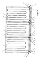
- the solar system like the FIG. 1 shows is composed of three solar modules 1.
- Each solar module 1 has a heat exchanger structure 2, which is shown only schematically as meandering tube.
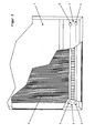
- Each solar module 1 has, as well as the FIG. 2 shows in an enlarged view, both on the input side 3 and on the output side 4 each have an inlet 5, 8 and a respective outlet 7, 6.
- the middle solar module 1 of the solar system FIG. 1 is connected with plug-in connection lines, for example hose connections 9, on its input side 3 with the output side 4 and correspondingly on its output side 4 with the input side 3 of the following solar module 1, in each case so that the inlets 8, 5 and the processes 6, 7 are connected.
- plug-in connection lines for example hose connections 9, on its input side 3 with the output side 4 and correspondingly on its output side 4 with the input side 3 of the following solar module 1, in each case so that the inlets 8, 5 and the processes 6, 7 are connected.
- the inlet 5 On the input side of the first solar module 1, the inlet 5 is connected to an inlet line 10 of a cooling medium supply, while the outlet 7 is closed on the inlet side of this first module with a dummy plug 11. Accordingly, on the output side 4 of the last solar module 1 of FIG. 1 shown on the right side of the assembly, the drain 6 is connected to a drain line which returns the refrigerant to the central cooling medium supply. On this output side 4 of the last solar module 1, the inlet 8 is correspondingly closed with a dummy plug 11.
- the solar system of FIG. 1 can be extended by further solar modules 1, which are incorporated between the first and the last module 1 with corresponding hose connections 9 in the arrangement.
- a solar system offers the advantage that the individual modules can be connected to each other with very short hose connections, without the need for additional inlet and outlet lines must be provided to connect the individual modules with the central cooling medium supply.
- Each solar module 1 is provided with the four terminals 5, 6, 7 and 8; only at the first and the last solar module 1 of the solar modules arranged one behind the other, the outlet 7 and the inlet 8 must be closed by a blanking plug 11.
Landscapes
- Engineering & Computer Science (AREA)
- Chemical & Material Sciences (AREA)
- Physics & Mathematics (AREA)
- Life Sciences & Earth Sciences (AREA)
- Sustainable Development (AREA)
- Sustainable Energy (AREA)
- Thermal Sciences (AREA)
- Combustion & Propulsion (AREA)
- Mechanical Engineering (AREA)
- General Engineering & Computer Science (AREA)
- Dispersion Chemistry (AREA)
- Photovoltaic Devices (AREA)
Applications Claiming Priority (1)
| Application Number | Priority Date | Filing Date | Title |
|---|---|---|---|
| DE202011103319U DE202011103319U1 (de) | 2011-07-12 | 2011-07-12 | "Solaranlage" |
Publications (2)
| Publication Number | Publication Date |
|---|---|
| EP2546582A2 true EP2546582A2 (fr) | 2013-01-16 |
| EP2546582A3 EP2546582A3 (fr) | 2016-10-19 |
Family
ID=45372985
Family Applications (1)
| Application Number | Title | Priority Date | Filing Date |
|---|---|---|---|
| EP12004919.2A Withdrawn EP2546582A3 (fr) | 2011-07-12 | 2012-07-02 | Installation solaire |
Country Status (2)
| Country | Link |
|---|---|
| EP (1) | EP2546582A3 (fr) |
| DE (1) | DE202011103319U1 (fr) |
Family Cites Families (6)
| Publication number | Priority date | Publication date | Assignee | Title |
|---|---|---|---|---|
| US4252103A (en) * | 1978-07-17 | 1981-02-24 | Advanced Energy Technology | Frame structure for a solar heating panel |
| AT373996B (de) * | 1980-03-14 | 1984-03-12 | Baierl Leopold | Sonnenkollektor |
| DE4241687C2 (de) * | 1992-12-10 | 1995-04-13 | Friedrich Mueller | Sonnenkollektor mit innenliegenden Verteilerleitungen |
| DE29912457U1 (de) * | 1999-07-21 | 1999-12-30 | Solarprojekt Energiesysteme GmbH, 88250 Weingarten | Thermischer Sonnenkollektor sowie Absorber für einen thermischen Sonnenkollektor |
| DE202006016294U1 (de) * | 2006-10-21 | 2008-02-28 | Consolar Solare Energiesysteme Gmbh | Solarkollektor mit kombiniertem Luftwärmeentzug |
| US20110146669A1 (en) * | 2009-12-23 | 2011-06-23 | Orion Energy Systems, Inc. | Solar thermal panel |
-
2011
- 2011-07-12 DE DE202011103319U patent/DE202011103319U1/de not_active Expired - Lifetime
-
2012
- 2012-07-02 EP EP12004919.2A patent/EP2546582A3/fr not_active Withdrawn
Non-Patent Citations (1)
| Title |
|---|
| None |
Also Published As
| Publication number | Publication date |
|---|---|
| EP2546582A3 (fr) | 2016-10-19 |
| DE202011103319U1 (de) | 2011-11-23 |
Similar Documents
| Publication | Publication Date | Title |
|---|---|---|
| DE112017000020B4 (de) | Neuartiges Schmier- und Kühlsystem für ein Getriebe einer Windkraftanlage | |
| EP2017561A2 (fr) | Accumulateur thermique | |
| DE102012012544A1 (de) | Verfahren zur Beheizung von Fußböden | |
| DE102014213671A1 (de) | Zellverbinder mit einer Temperierungsvorrichtung, Batteriezelle, Batteriemodul und Kraftfahrzeug | |
| EP3270066A1 (fr) | Procédé de fonctionnement d'un système d'alimentation en énergie pourvu d'un accumulateur de chaleur latente, système d'alimentation en énergie permettant de mettre en oeuvre le procédé et champ de collecteur pour un système d'alimentation en énergie | |
| CH701134A2 (de) | Vorrichtung zur Wärmeregelung. | |
| DE102011100526A1 (de) | Leistungselektronische Anordnung mit Flüssigkeitskühlung | |
| DE102013221573A1 (de) | Thermoelektrischer Generator | |
| EP0647818B1 (fr) | Système de chauffage décentralisé dans lequel usage est fait de techniques de conduites d'écoulement multiples | |
| EP2546582A2 (fr) | Installation solaire | |
| DE102011106022A1 (de) | Warmwassererzeugungs-, Speicher- und Abgabevorrichtung | |
| DE212013000132U1 (de) | Kesselanlagen-System sowie Komponenten und Bauteile dieses Systems | |
| DE20103062U1 (de) | Verteilerstation für eine Heizungs- und Wasserversorgungsanlage | |
| DE102014000901A1 (de) | Solaranlage | |
| DE102014007598A1 (de) | Verfahren und Anordnung zur Reduzierung von Rücklauftemperaturniveaus in Heizungsanlagen mit beliebig vielen Heizkreisen | |
| DE2556772A1 (de) | Verfahren und vorrichtung zur wirtschaftlichen ausnutzung der abwaerme von waermekraftwerken | |
| DE102009007186A1 (de) | Plattenwärmetauscher | |
| DE102019207638A1 (de) | Wärmeübertragervorrichtung mit mehreren Wärmeübertragern mit jeweiligen Verteil- und Sammelabschnitten sowie Kälteanlage und Kraftfahrzeug mit Kälteanlage | |
| DE102011100543A1 (de) | Leistungselektronische Anordnung mit Flüssigkeitskühlung | |
| AT513841B1 (de) | Verfahren zur Beheizung von Gebäuden | |
| DE102012011567A1 (de) | Heiz- und/oder Kühlanlage | |
| EP2553354A1 (fr) | Système d'expansion du circuit caloporteur d'une centrale solaire thermique | |
| EP4366481A1 (fr) | Module de refroidissement de bâti pour bâti de support | |
| WO2001011198A1 (fr) | Centrale, en particulier centrale industrielle | |
| DE102009024966B4 (de) | Vorrichtung zur Übertragung der mittels einer Wärmepumpe gewonnenen Energie auf andere Baugruppen und Baugruppe bestehend aus mehreren solchen Vorrichtungen |
Legal Events
| Date | Code | Title | Description |
|---|---|---|---|
| PUAI | Public reference made under article 153(3) epc to a published international application that has entered the european phase |
Free format text: ORIGINAL CODE: 0009012 |
|
| AK | Designated contracting states |
Kind code of ref document: A2 Designated state(s): AL AT BE BG CH CY CZ DE DK EE ES FI FR GB GR HR HU IE IS IT LI LT LU LV MC MK MT NL NO PL PT RO RS SE SI SK SM TR |
|
| AX | Request for extension of the european patent |
Extension state: BA ME |
|
| PUAL | Search report despatched |
Free format text: ORIGINAL CODE: 0009013 |
|
| AK | Designated contracting states |
Kind code of ref document: A3 Designated state(s): AL AT BE BG CH CY CZ DE DK EE ES FI FR GB GR HR HU IE IS IT LI LT LU LV MC MK MT NL NO PL PT RO RS SE SI SK SM TR |
|
| AX | Request for extension of the european patent |
Extension state: BA ME |
|
| RIC1 | Information provided on ipc code assigned before grant |
Ipc: F24J 2/46 20060101AFI20160909BHEP Ipc: F24J 2/26 20060101ALI20160909BHEP |
|
| STAA | Information on the status of an ep patent application or granted ep patent |
Free format text: STATUS: THE APPLICATION IS DEEMED TO BE WITHDRAWN |
|
| 18D | Application deemed to be withdrawn |
Effective date: 20170420 |