EP2546596A2 - Composant d'échangeur de chaleur pour procédés thermiques - Google Patents
Composant d'échangeur de chaleur pour procédés thermiques Download PDFInfo
- Publication number
- EP2546596A2 EP2546596A2 EP12172003A EP12172003A EP2546596A2 EP 2546596 A2 EP2546596 A2 EP 2546596A2 EP 12172003 A EP12172003 A EP 12172003A EP 12172003 A EP12172003 A EP 12172003A EP 2546596 A2 EP2546596 A2 EP 2546596A2
- Authority
- EP
- European Patent Office
- Prior art keywords
- heat exchanger
- elements
- encapsulation
- exchanger component
- medium
- Prior art date
- Legal status (The legal status is an assumption and is not a legal conclusion. Google has not performed a legal analysis and makes no representation as to the accuracy of the status listed.)
- Withdrawn
Links
Images



Classifications
-
- F—MECHANICAL ENGINEERING; LIGHTING; HEATING; WEAPONS; BLASTING
- F28—HEAT EXCHANGE IN GENERAL
- F28F—DETAILS OF HEAT-EXCHANGE AND HEAT-TRANSFER APPARATUS, OF GENERAL APPLICATION
- F28F21/00—Constructions of heat-exchange apparatus characterised by the selection of particular materials
- F28F21/06—Constructions of heat-exchange apparatus characterised by the selection of particular materials of plastics material
- F28F21/067—Details
-
- F—MECHANICAL ENGINEERING; LIGHTING; HEATING; WEAPONS; BLASTING
- F28—HEAT EXCHANGE IN GENERAL
- F28F—DETAILS OF HEAT-EXCHANGE AND HEAT-TRANSFER APPARATUS, OF GENERAL APPLICATION
- F28F2255/00—Heat exchanger elements made of materials having special features or resulting from particular manufacturing processes
- F28F2255/14—Heat exchanger elements made of materials having special features or resulting from particular manufacturing processes molded
- F28F2255/146—Heat exchanger elements made of materials having special features or resulting from particular manufacturing processes molded overmolded
Definitions
- the invention relates to a heat exchanger component for conducting a liquid and / or gaseous operating medium according to the preamble of claim 1.
- the invention is based on a heat exchanger component for the pressure-tight conduction of a liquid and / or gaseous operating medium, with at least two elements which in the assembled state form at least one cavity, which is provided for a flow of the working medium, wherein at least the two elements at least partially from a Plastic are formed, which is provided for a pressure-tight encapsulation.
- the heat exchanger component has at least one encapsulation, which connects at least the two elements pressure-tight together.
- a lightweight heat exchanger component can be provided, which can also be easily processed, whereby a low-cost heat exchanger component is provided, which is provided for a line of a resource medium in a heating system.
- the at least two elements can be connected to each other in a particularly simple and secure manner.
- a "heat exchanger component” should be understood to mean, in particular, a component which is intended to effect a heat transfer from one liquid and / or gaseous operating medium to another liquid and / or gaseous operating medium in a thermal process and thereby fluidically the at least two operating mediums separate, as in particular in a building heating system in conjunction with at least one resource medium intended for heating and / or cooling a building.
- a "medium medium” is to be understood in particular a liquid and / or gaseous medium, which is intended for heat transfer, such as in particular in the heating system directly heated medium, which is preferably an exhaust gas of a fuel heater, and / or an indirectly heated medium , which is preferably heated by a heat exchanger from the directly heated medium, such as in particular a liquid medium.
- the operating medium passed through the heat exchanger component can in principle be chemically active.
- a “cavity” should also be understood as meaning a channel for conducting the medium of the medium, which has at least one defined inflow opening and at least one defined outflow opening, wherein the inflow opening and the outflow opening are connected to one another through the cavity which is provided for the flow of the medium ,
- a "joined state” should be understood in particular a state in which the at least two elements are joined together with at least one surface provided for this purpose, wherein the at least two elements are preferably firmly connected together in the assembled state.
- a “coating” is to be understood in particular a type of connection of the at least two elements, which is at least partially mounted in an injection molding process.
- pressure-tight is to be understood in particular that the at least two elements are so tightly interconnected by the encapsulation that a leakage, especially to the outside, at a provided for building heating systems test pressure, for example, in the range of 3 bar to 10 bar can, or is negligible in other thermal processes.
- the at least two elements and the encapsulation are made of the same plastic.
- the encapsulation can be made particularly simple.
- the term "identical plastic” should be understood as meaning in particular a plastic which is the same in its chemical composition. In principle, however, it is also conceivable to form the elements and / or the encapsulation from different plastics provided for the cohesive connection.
- the plastic is preferably designed as a high-temperature plastic, in particular as a PPS.
- a high-temperature-resistant plastic can be found for the heat exchanger component, due to which the heat exchanger component is particularly resilient.
- other high-temperature resistant plastics such as in particular corrosion-resistant High temperature plastics, to be used.
- PPS polyphenylene sulfide
- other high-temperature resistant thermoplastic materials can be used.
- the high temperature plastic is fiber reinforced.
- the plastic and / or a fiber reinforcement are chemically resistant.
- the fiber reinforcement is advantageously provided to increase a thermal conductivity.
- the at least two elements have congruently arranged recesses which are provided for receiving at least part of the encapsulation.
- the tight connection of the at least two elements in particular in the case of a large extent and / or in an embodiment in which the elements are provided for forming a plurality of cavities, can advantageously be achieved.
- large is meant in particular an extension over several centimeters, in particular over a few decimeters.
- a "recess” is to be understood in particular a recess which extends through the element.
- congruent arranged is to be understood in particular that each of the elements has at least one recess and the recesses in the assembled state overlie each other so that they form a recess passing through both elements recess.
- the at least two elements are connected to one another in a material-locking manner, at least in partial regions.
- the at least two elements can be connected to one another particularly firmly.
- at least in subregions is to be understood in particular that the two elements are at least in the sub-areas in which the encapsulation is attached, are materially interconnected.
- the heat exchanger component has at least one insert part, which is at least partially inserted into the encapsulation in order to reinforce a connection of the at least two elements.
- the heat exchanger component can be designed for higher test pressures, resulting in a higher reliability.
- the at least one insert part differs with regard to its material from the material of the extrusion coating.
- Particularly preferred are inserts made of a fiber-reinforced plastic, in particular Corbonmaschine inserts.
- the insert can in principle be formed as a single insert, which is selectively introduced into the recess before encapsulation or on an edge of the at least two elements is arranged.
- fibers or the like are introduced as inserts into a material for the encapsulation, which are then attached together with the encapsulation.
- the heat exchanger component comprises at least one sealing element which is inserted between the two elements.
- the elements form a distributor plate and / or a system plate for a heating heat exchanger.
- the heat exchanger component according to the invention can be used particularly advantageously, as a result of which a component which otherwise has a high design complexity can be realized simply and inexpensively.
- this can be dispensed with a screwed and / or otherwise form-fitting connection of the two elements, whereby a secure and durable durable connection can be created.
- a "distributor plate” is to be understood in particular as meaning a plate which is intended to distribute the operating medium to heat exchanger tubes.
- a “system plate” is to be understood, in particular, as a plate which has cavities and through which the operating medium can flow.
- At least one of the elements has at least one operating medium connection, which is provided for the connection of an inflow and / or an outflow for the operating medium.
- the operating medium can be easily introduced into the heat exchanger component.
- At least one of the elements has at least one connection for connecting at least one heat exchanger tube.
- the heat exchanger component can be designed to be particularly advantageous as a distributor plate for a tube heat exchanger.
- a "connection for connecting a heat exchanger tube” should be understood in particular a plug-in connection, in which the heat exchanger tube can be inserted.
- the connection for connecting a heat exchanger tube for a cohesive connection of the heat exchanger tube, in particular by means of an encapsulation is provided.
- a heat exchanger with at least one heat exchanger component for conducting a liquid and / or gaseous medium medium which has at least two formed of a plastic elements which form at least one cavity in the assembled state, which for a Flow of the medium medium is provided, and which are connected by at least one encapsulation pressure-tight with each other, in particular with a heat exchanger component according to the invention proposed.
- a simple and cost-effective heat exchanger for a heating system, in particular a building heating system can be provided.
- the heat exchanger component which has the at least two elements, is designed as a distributor plate and / or system plate.
- the heat exchanger has at least one heat exchanger tube
- the lengths is compensating connected to at least one of the elements.
- a thermal expansion-induced longitudinal expansion of the heat exchanger tube which deviates from other components, for example due to different Temperaturbeetzwegungen and / or different coefficients of linear expansion, are easily compensated.
- length compensating is to be understood in particular that the heat exchanger tube is slidably connected along its main extension direction to the element, in particular by a connector.
- the heat exchanger comprises at least one further heat exchanger component, which is at least partially formed from plastic and connected by an encapsulation with the heat exchanger component.
- a stable complex structure can be provided, such as in particular a plate heat exchanger having a plurality of interconnected system plates, which are each formed according to the invention.
- a method for producing a heat exchanger component according to the invention in particular for producing a heat exchanger according to the invention, proposed, in which at least two formed from a plastic elements for forming at least one cavity, which is provided for a flow of the working medium, assembled and at least one encapsulation with each other get connected.
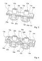
- FIGS. 1 to 4 a first embodiment of a heat exchanger component 1 3a according to the invention is shown.
- the heat exchanger component 1 3a is provided for a heat exchanger of a building heating system.
- the heat exchanger component 1 3a forms a distributor plate, which is provided for installation in the heat exchanger, not shown, and to which a plurality of heat exchanger tubes can be connected.
- the heat exchanger tubes are intended to effect heat exchange between a resource medium passing through the heat exchanger tubes and a resource medium surrounding the heat exchanger tubes.
- the heat exchanger component 1 3a has two elements 10a, 11a, which form the distributor plate.
- the distributor plate is intended to guide the operating medium defined by the heat exchanger tubes.
- One of the two elements 10a, 11a forms a connection plate for connecting the heat exchanger tubes.
- the element 11a comprises a plurality of connections 22a for the heat exchanger tubes.
- the terminals 22a for the heat exchanger tubes are formed as recesses in the element 11a.
- the connections 22a form plug-in connections into which the heat exchanger tubes can be inserted.
- the two elements 10a, 11a for the passage of the medium medium, which is to be passed into the heat exchanger tubes, are provided.
- the two elements 10a, 11a form a plurality of mutually separate cavities 12a forming conduits for the working medium.
- the cavities 12a connect at least two of the connections 22a for the heat exchanger tubes to one another.
- the recesses are intended to direct the working medium from one of the heat exchanger tubes into the next heat exchanger tube.
- the one element 11a is provided essentially for the formation of the connections 22a for the heat exchanger tubes.
- the terminals 22a are formed as recesses passing through the element 11a.
- the other element 10a is provided to connect the terminals 22a with each other.
- one of the two elements 10a, 11a may additionally have at least one operating medium connection, which is provided for the connection of an inlet or outlet.
- the two elements 10a, 11a form a distributor plate, which is provided only for deflecting the operating medium flowing through the heat exchanger tubes.
- the operating fluid connections for the inflow and outflow of the medium medium in the heat exchanger tubes are realized in this embodiment by a second distributor plate, not shown, which is arranged at opposite ends of the heat exchanger tubes and which is configured substantially equal.
- connection elements are firmly connected to the element 11a.
- the connection elements could be formed of a plastic which differs from the plastic of the element 11a.
- the connection elements made of metal.
- the connection elements are connected to the element 11a by means of an encapsulation.
- the two elements 10a, 11a are formed of a plastic. On one side 19a, 20a, on which the two elements 10a, 11a are joined together, both elements 10a, 11a are substantially planar.
- the terminals 22a of the one element 11a which are provided for the connections of the heat exchanger tubes, are implemented by means of recesses in the substantially planely executed side 20a of the element 11a.
- the other element 10a has depressions on the substantially flat side 19a, through which the recesses formed by the connections 22a can be connected to one another.
- the substantially planar sides 19a, 20a are designed sufficiently flat in the context of a manufacturing tolerance in order to connect the elements 10a, 11a to one another in a pressure-tight manner. In the assembled state, the individual recesses and recesses form fluidically separated operating medium lines, through which the operating medium can be passed.
- the heat exchanger component 1 3a comprises an encapsulation 14a.
- the two elements 10a, 11a and the encapsulation 14a are made of the same plastic.
- the plastic used is PPS (polyphenylene sulfide).
- the elements 10a, 11a are thus made of a high-performance plastic, which is designed for a constant temperature load with temperatures of about 80 ° C to 120 ° C, as they occur in a resource medium of a heating system.
- the plastic from which the elements 10a, 11a are made designed for a continuous temperature load of at least 200 ° C, wherein the elements 10a, 11a can generally tolerate at least briefly higher temperature loads.
- the elements 10a, 11a may be made of a carbon fiber reinforced plastic.
- the elements 10a, 11a comprise a plurality of recesses 15a, which are arranged congruently in the elements 10a, 11a.
- the recesses 15a are one above the other.
- two mutually opposite recesses 15a form a single continuous Recess, which engages through both elements 10a, 11a.
- the recesses 15a in the elements 10a, 11a are formed as bores.
- the elements 10a, 11a further each have an edge, which is also provided for a congruent arrangement. Edge dimensions of the two elements 10a, 11a are approximately the same size.
- the two elements 10a, 11a can be superimposed congruent with each other, wherein the elements 10a, 11a then have in a region which is enclosed by the edge, the sweeping recesses 15a.
- the sealing elements 25a are designed as ring seals.
- the sealing elements 25a are each arranged so that they are completely disposed between the two elements 10a, 11a.
- each of the sealing elements 25a passes around one of the recesses, which are inserted into the element 10a and which in the assembled state define one of the cavities 12a.
- the sealing elements 25a may be made of rubber, for example.
- the elements 10a, 11a have for receiving the sealing elements 25a recesses, which lie congruently in the assembled state one above the other. In the assembled state, the sealing elements 25a are completely fixed by the connection of the elements 10a, 11a via the encapsulation 14a.
- the two elements 10a, 11a are placed congruently on each other. Subsequently, the elements 10a, 11a are encapsulated at their edge and in the region of the recesses 15a. The encapsulation 14a thus engages around the common edge of the elements 10a, 11a. In addition, the encapsulation 14a passes through the recesses 15a. The encapsulation 14a is applied in one piece in an encapsulation process. In principle, however, it is also conceivable to overmold the edge and / or the individual recesses 15a at least partially in separate steps, whereby the overmoulding 14a would then have a plurality of subregions.
- the encapsulation 14a connects the elements 10a, 11a to one another in a pressure-tight manner.
- the overmoulding 14a effects a force which presses the elements 10a, 11a against one another. Due to the planar configuration of the elements 10a, 11a on the superposed sides 19a, 20a, gaps between the elements 10a, 11a are negligibly small, and a pressure-tight connection of the elements 10a, 11a is realized.
- the connection is designed at least for pressures of the medium medium less than 5 bar.
- insert parts 26a are inserted into the encapsulation 14a.
- the inserts 26a are designed in the illustrated embodiment as fibers which are contained in the encapsulation 14a.
- the fibers are thereby introduced into the encapsulation 14a before the encapsulation process. They have a substantially higher melting point than the plastic from which the encapsulation 14a is.
- rigid inserts which are positioned on the elements 10a, 11a before the encapsulation process and which are completely enclosed by the encapsulation 14a after the encapsulation process.
- brackets can be arranged on the edge of the elements 10a, 11a as inserts, which are mounted before the encapsulation process.
- inserts that are passed through the recesses 15a can be carried out, for example, in the form of anchor elements, which are only fixed by the encapsulation 14a. But it is also conceivable execution as parentheses.
- the encapsulation 14a connects the elements 10a, 11a in partial areas 16a, 17a in a material-locking manner.
- the elements 10a, 11a are heated to a temperature which is close to a melting temperature of the plastic.
- the elements 10a, 11a further heat, whereby the two elements 10a, 11a in the partial areas 16a, 17a, in which the encapsulation 14a encloses them, merge materially together.
- the two elements 10a, 11a lie flat against each other, but are not connected to one another in a material-locking manner. Since the two elements 10a, 11a and the overmoulding 14a are made of the same plastic, the encapsulation 14a results in a partially integral formation of the two elements 10a, 11a.
- One of the subregions 16a, 17a, in which the elements 10a, 11a are connected to one another in a material-locking manner, is the edge of the elements 10a, 11a.
- the encapsulation 14a surrounds both elements 10a, 11a, whereby the elements 10a, 11a partially fuse together during the application of the encapsulation 14a.
- the encapsulation 14a surrounds the elements 10a, 11a in the region of the recesses 15a, whereby the two elements 10a, 11a merge with each other also in this portion 17a, which is defined by the recesses 15a.
- FIG. 5 shows a part of a heat exchanger with a heat exchanger component 13b, which is designed substantially analogously to the previous embodiment.
- the heat exchanger component 1 3b comprises two elements 10b, 11b, which are formed from plastic and are pressure-tightly interconnected by an encapsulation 14b.
- the elements 10b, 11b surround a plurality of cavities 1b, which are provided for a flow of a medium medium.
- the heat exchanger component 1 3b which has the elements 10b, 11b which are materially interconnected by means of the encapsulation 14b, is designed as a distributor plate.
- the heat exchanger further comprises a plurality of heat exchanger tubes 18b connected to one of the elements 10b, 11b.
- the member 11b includes a plurality of ports 22b for the heat exchanger tubes 18b.
- the element 10b has a resource port 21b provided for inflow or outflow of the resource medium.
- the heat exchanger tubes 18b are connected to compensate for the length of the element 11b.
- the terminals 22b form receptacles for the heat exchanger tubes 18b.
- the heat exchanger tubes 18 b are inserted into the terminals 22 b, they can at a Length change, which can be caused in particular by temperature changes, move in the terminals 22b. Length changes of the heat exchanger tubes 18b, which may be based, for example, temperature changes are thus compensated by the terminals 22b.
- the heat exchanger tubes 18b may be made of a metal in this case.
- the heat exchanger component 1 3b itself has, in contrast to the previous embodiment, a substantially larger dimensions, structurally corresponds substantially but the previous embodiment. With regard to an embodiment of the heat exchanger component 1 3b itself should therefore be made to the description of the preceding embodiment.
- FIG. 6 shows as a further embodiment of the invention, a heat exchanger component 1 3c, which is formed as a system plate.
- the system plate is intended for a heat exchanger.
- the heat exchanger component 13c comprises two elements 10c, 11c, which in the assembled state form a cavity, which is provided for a flow of a medium medium.
- the heat exchanger component 1 3c is provided for a direct heat exchange between the operating medium carried in the heat exchanger component 1 3c and a surrounding operating medium.
- FIG. 6 shows the heat exchanger component 1 3c before it is overmolded.
- the non-illustrated cavity in the heat exchanger component 1 3c is formed as a single, continuous operating line, which passes through the heat exchanger component 1 3c.
- the operating medium line is thereby multiple curved within the heat exchanger component 1 3c, whereby a length which has the operating medium line is substantially greater than an edge length of the elements 10c, 11c.
- the operating medium line passes through the heat exchanger component 1 3c with a course that is provided for a countercurrent process, ie, the operating medium line runs in a central portion in each case parallel to an edge of the elements 10c, 11c and is deflected respectively in edge regions by an angle of 180 degrees ,
- One of the elements 10c, 11c forms a lateral boundary of the operating medium line.
- the resource line is inserted in the other of the elements 10c, 11c.
- a groove or a groove-shaped recess is introduced into the element 11c, the course of which defines a course of the operating medium line in the assembled state.
- the groove can be introduced, for example, by means of a milling process in the element 11c. In principle, however, other methods are conceivable.
- the heat exchanger component 1 3c shown in this embodiment is provided for connection to further heat exchanger components 23c, 24c (cf. Fig. 5 ).
- the further heat exchanger components 23c, 24c are designed analogously to the illustrated heat exchanger component 1 3c.
- the heat exchanger components 1 3c, 23c, 24c can be interconnected in any number with other, not shown heat exchanger components to a heat exchanger, wherein the medium medium, the heat exchanger components 1 3c, 23c, 24c flows through successively and / or in parallel.
- the heat exchanger components 1 3c, 23c, 24c are arranged at a distance, whereby the operating medium surrounding the heat exchanger components 1 3c, 23c, 24c can flow between the heat exchanger components 1 3c, 23c, 24c, while the other operating medium in the heat exchanger components 1 3c, 23c, 24c to be led.
- the heat exchanger components 1 3c, 23c, 24c are coupled to each other only on two opposite sides, whereby the surrounding operating medium on one side of the heat exchanger components 1 3c, 23c, 24c between the heat exchanger components 1 3c, 23c, 24c flow in and out on the opposite side can.
- the heat exchanger components 1 3c, 23c, 24c may basically have any basic shape, such as round or oval. In principle, it is also conceivable to design the heat exchanger component 1 3c in three or more parts. For example, it is conceivable to introduce a penetrating recess in one of the elements 10c, 11c to form the operating medium line and then to form the recess by means of an encapsulation fixedly connected to the element having the recess as an operating line. In addition, it is also conceivable by an equivalent embodiment to provide a multilayered heat exchanger component, for example with four or five elements, in which the different elements are used to form a complex equipment line system, for example with crossing equipment lines.
- FIG. 6 shows a further composite of heat exchanger components 13d, 23d, 24d.
- the heat exchanger components 13d, 23d, 24d each have a recess which is provided to introduce the surrounding operating medium into an intermediate space between the heat exchanger components 13d, 23d, 24d.
- the heat exchanger components 13d, 23d, 24d are coupled to each other at three of four sides, whereby the surrounding operating medium, which flows in via the recesses, can flow out on the remaining side of the heat exchanger components 13d, 23d, 24d.
- FIG. 7 shows a further composite of heat exchanger components 1 3e, 23e, 24e, which also each have a recess which is intended to introduce the surrounding operating medium in a space between the heat exchanger components 1 3e, 23e, 24e.
- the recess is arranged centrally and the heat exchanger components 1 3e, 23e, 24e are coupled together so that the surrounding operating medium, which flows in through the recesses, can flow out on all sides of the heat exchanger components 1 3e, 23e, 24e.
- the recess can be arranged at any desired location.
Landscapes
- Engineering & Computer Science (AREA)
- Physics & Mathematics (AREA)
- Thermal Sciences (AREA)
- Mechanical Engineering (AREA)
- General Engineering & Computer Science (AREA)
- Heat-Exchange Devices With Radiators And Conduit Assemblies (AREA)
Applications Claiming Priority (1)
| Application Number | Priority Date | Filing Date | Title |
|---|---|---|---|
| DE102011106995A DE102011106995A1 (de) | 2011-07-09 | 2011-07-09 | Wärmetauscherbauteil für thermische Prozesse |
Publications (2)
| Publication Number | Publication Date |
|---|---|
| EP2546596A2 true EP2546596A2 (fr) | 2013-01-16 |
| EP2546596A3 EP2546596A3 (fr) | 2015-01-14 |
Family
ID=46298284
Family Applications (1)
| Application Number | Title | Priority Date | Filing Date |
|---|---|---|---|
| EP12172003.1A Withdrawn EP2546596A3 (fr) | 2011-07-09 | 2012-06-14 | Composant d'échangeur de chaleur pour procédés thermiques |
Country Status (2)
| Country | Link |
|---|---|
| EP (1) | EP2546596A3 (fr) |
| DE (1) | DE102011106995A1 (fr) |
Cited By (1)
| Publication number | Priority date | Publication date | Assignee | Title |
|---|---|---|---|---|
| EP2881514A1 (fr) * | 2013-12-05 | 2015-06-10 | Miele & Cie. KG | Appareils ménager comme un sèche-linge, lave-vaisselle ou sèche-linge ayant une pompe à chaleur |
Citations (2)
| Publication number | Priority date | Publication date | Assignee | Title |
|---|---|---|---|---|
| DE2011621A1 (en) * | 1970-03-11 | 1971-11-11 | Kunststoffwerk Gebrüder Anger GmbH & Co, München, 8000 München | Plastics heat-exchanging heater |
| DE3536527A1 (de) * | 1984-10-20 | 1986-04-24 | Volkswagen AG, 3180 Wolfsburg | Waermetauscherblock fuer einen fluessigkeits-luft-waermetauscher |
Family Cites Families (7)
| Publication number | Priority date | Publication date | Assignee | Title |
|---|---|---|---|---|
| DE2749205A1 (de) * | 1977-11-03 | 1979-05-10 | Volkswagenwerk Ag | Roehrenwaermetauscher |
| DE8706084U1 (de) * | 1987-04-28 | 1987-06-19 | Süddeutsche Kühlerfabrik Julius Fr. Behr GmbH & Co KG, 7000 Stuttgart | Wärmetauscher, insbesondere für Verbrennungskraftmaschinen von Kraftfahrzeugen |
| DE4202024A1 (de) * | 1992-01-25 | 1993-07-29 | Abb Patent Gmbh | Isolierkuehldose zum abfuehren der verlustwaerme von halbleiterbauelementen |
| DE4237117A1 (de) * | 1992-11-03 | 1994-05-05 | Bosch Siemens Hausgeraete | Verfahren zum Herstellen eines Pakets von Wärmetauscher-Platten für einen Haushalt-Wäschetrockner, Werkzeug für ein solches Herstellungsverfahren und nach diesem Verfahren hergestelltes Plattenpaket |
| EP1411311A1 (fr) * | 2002-10-17 | 2004-04-21 | Jean Luc Deloy | Appareil de chauffage comprenant un système d'échange de chaleur |
| DE202008008437U1 (de) * | 2008-06-24 | 2008-10-09 | Paul Craemer Gmbh | Kunststoffumspritzter Plattenwärmetauscher |
| DE102009054345B4 (de) * | 2009-09-30 | 2018-11-22 | Etimex Technical Components Gmbh | Ein Fluid verarbeitendes Haushaltsgerät mit einem Wärmeübertrager mit zwei oder mehr Behältern und Verfahren zum Betreiben |
-
2011
- 2011-07-09 DE DE102011106995A patent/DE102011106995A1/de not_active Withdrawn
-
2012
- 2012-06-14 EP EP12172003.1A patent/EP2546596A3/fr not_active Withdrawn
Patent Citations (2)
| Publication number | Priority date | Publication date | Assignee | Title |
|---|---|---|---|---|
| DE2011621A1 (en) * | 1970-03-11 | 1971-11-11 | Kunststoffwerk Gebrüder Anger GmbH & Co, München, 8000 München | Plastics heat-exchanging heater |
| DE3536527A1 (de) * | 1984-10-20 | 1986-04-24 | Volkswagen AG, 3180 Wolfsburg | Waermetauscherblock fuer einen fluessigkeits-luft-waermetauscher |
Cited By (1)
| Publication number | Priority date | Publication date | Assignee | Title |
|---|---|---|---|---|
| EP2881514A1 (fr) * | 2013-12-05 | 2015-06-10 | Miele & Cie. KG | Appareils ménager comme un sèche-linge, lave-vaisselle ou sèche-linge ayant une pompe à chaleur |
Also Published As
| Publication number | Publication date |
|---|---|
| EP2546596A3 (fr) | 2015-01-14 |
| DE102011106995A1 (de) | 2013-01-10 |
Similar Documents
| Publication | Publication Date | Title |
|---|---|---|
| DE102012005870A1 (de) | Kühlvorrichtung für eine Fahrzeugbatterie sowie Fahrzeugbatterie mit Kühlvorrichtung | |
| WO2023046530A1 (fr) | Dissipateur thermique | |
| EP3163242A1 (fr) | Indirekter ladeluftkühler | |
| DE102012020882B4 (de) | Verfahren zur Herstellung eines Wärmetauschers für ein Kraftfahrzeug und Wärmetauscher für ein Kraftfahrzeug | |
| DE102017203058A1 (de) | Wärmeübertrager und Reaktor | |
| EP0109097B1 (fr) | Echangeur de chaleur à plaques | |
| DE102010016099A1 (de) | Zylinderkopf einer Brennkraftmaschine | |
| EP2929211B1 (fr) | Amortisseur de chocs pour véhicule avec bride de raccordement à un tube de module externe | |
| WO2017129768A1 (fr) | Échangeur de chaleur-mélangeur de type x à cavité | |
| DE102012208771A1 (de) | Wärmetauscher zum Temperieren eines ersten Fluids unter Verwendung eines zweiten Fluids | |
| DE19837671A1 (de) | Statischer Mischer | |
| EP4089357A1 (fr) | Echangeur de chaleur | |
| WO2017072212A1 (fr) | Module de refroidissment pour une unité photovoltaïque | |
| DE3737433A1 (de) | Baustein fuer einen kreuzstrom-roehrenwaermeaustauscher und daraus hergestellter waermeaustauscher | |
| DE69613918T2 (de) | Wärmetauscher mit Adapter | |
| WO2014083036A1 (fr) | Échangeur de chaleur à plaques de type étanchéifié | |
| WO2003067095A1 (fr) | Systeme de clapets multiples pour ecoulement de fluides | |
| DE102011106995A1 (de) | Wärmetauscherbauteil für thermische Prozesse | |
| DE2011621A1 (en) | Plastics heat-exchanging heater | |
| DE102019127956A1 (de) | Seitenanspritzdüse und spritzgiesswerkzeug | |
| DE102004020602A1 (de) | Plattenwärmetauscher mit Strömungswegen für drei Wärmetauschfluide | |
| EP3194873B1 (fr) | Échangeur de chaleur et procédé de fabrication d'un échangeur de chaleur | |
| DE202008017839U1 (de) | Solarflachkollektor und dessen Herstellung | |
| EP3239641A1 (fr) | Tube plat pour un caloporteur | |
| DE102021213921A1 (de) | Wärmetauscher mit zweiteiligen durchgangsformstücken |
Legal Events
| Date | Code | Title | Description |
|---|---|---|---|
| PUAI | Public reference made under article 153(3) epc to a published international application that has entered the european phase |
Free format text: ORIGINAL CODE: 0009012 |
|
| AK | Designated contracting states |
Kind code of ref document: A2 Designated state(s): AL AT BE BG CH CY CZ DE DK EE ES FI FR GB GR HR HU IE IS IT LI LT LU LV MC MK MT NL NO PL PT RO RS SE SI SK SM TR |
|
| AX | Request for extension of the european patent |
Extension state: BA ME |
|
| PUAL | Search report despatched |
Free format text: ORIGINAL CODE: 0009013 |
|
| AK | Designated contracting states |
Kind code of ref document: A3 Designated state(s): AL AT BE BG CH CY CZ DE DK EE ES FI FR GB GR HR HU IE IS IT LI LT LU LV MC MK MT NL NO PL PT RO RS SE SI SK SM TR |
|
| AX | Request for extension of the european patent |
Extension state: BA ME |
|
| RIC1 | Information provided on ipc code assigned before grant |
Ipc: F28F 21/06 20060101AFI20141205BHEP |
|
| 17P | Request for examination filed |
Effective date: 20150710 |
|
| RBV | Designated contracting states (corrected) |
Designated state(s): AL AT BE BG CH CY CZ DE DK EE ES FI FR GB GR HR HU IE IS IT LI LT LU LV MC MK MT NL NO PL PT RO RS SE SI SK SM TR |
|
| STAA | Information on the status of an ep patent application or granted ep patent |
Free format text: STATUS: EXAMINATION IS IN PROGRESS |
|
| 17Q | First examination report despatched |
Effective date: 20170119 |
|
| STAA | Information on the status of an ep patent application or granted ep patent |
Free format text: STATUS: THE APPLICATION IS DEEMED TO BE WITHDRAWN |
|
| 18D | Application deemed to be withdrawn |
Effective date: 20190227 |