EP2546677A1 - Verfahren und Radarsensor zur Unterscheidung zwischen Vorwärtsfahrt und Rückwärtsfahrt bei einem Fahrzeug - Google Patents
Verfahren und Radarsensor zur Unterscheidung zwischen Vorwärtsfahrt und Rückwärtsfahrt bei einem Fahrzeug Download PDFInfo
- Publication number
- EP2546677A1 EP2546677A1 EP12168296A EP12168296A EP2546677A1 EP 2546677 A1 EP2546677 A1 EP 2546677A1 EP 12168296 A EP12168296 A EP 12168296A EP 12168296 A EP12168296 A EP 12168296A EP 2546677 A1 EP2546677 A1 EP 2546677A1
- Authority
- EP
- European Patent Office
- Prior art keywords
- radar sensor
- radar
- vehicle
- frequency
- spectrum
- Prior art date
- Legal status (The legal status is an assumption and is not a legal conclusion. Google has not performed a legal analysis and makes no representation as to the accuracy of the status listed.)
- Granted
Links
- 238000000034 method Methods 0.000 title claims abstract description 21
- 230000000630 rising effect Effects 0.000 claims abstract description 6
- 238000001228 spectrum Methods 0.000 claims description 36
- 230000005855 radiation Effects 0.000 abstract description 2
- 238000010586 diagram Methods 0.000 description 6
- 230000006870 function Effects 0.000 description 5
- 230000005540 biological transmission Effects 0.000 description 3
- 230000003247 decreasing effect Effects 0.000 description 2
- 238000001514 detection method Methods 0.000 description 2
- 238000002592 echocardiography Methods 0.000 description 2
- 230000003044 adaptive effect Effects 0.000 description 1
- 230000001186 cumulative effect Effects 0.000 description 1
- 230000007423 decrease Effects 0.000 description 1
- 238000011161 development Methods 0.000 description 1
- 230000018109 developmental process Effects 0.000 description 1
- 230000000694 effects Effects 0.000 description 1
- 238000011156 evaluation Methods 0.000 description 1
- 238000001914 filtration Methods 0.000 description 1
- 238000009434 installation Methods 0.000 description 1
- 238000005096 rolling process Methods 0.000 description 1
- 230000009466 transformation Effects 0.000 description 1
Images



Classifications
-
- G—PHYSICS
- G01—MEASURING; TESTING
- G01S—RADIO DIRECTION-FINDING; RADIO NAVIGATION; DETERMINING DISTANCE OR VELOCITY BY USE OF RADIO WAVES; LOCATING OR PRESENCE-DETECTING BY USE OF THE REFLECTION OR RERADIATION OF RADIO WAVES; ANALOGOUS ARRANGEMENTS USING OTHER WAVES
- G01S13/00—Systems using the reflection or reradiation of radio waves, e.g. radar systems; Analogous systems using reflection or reradiation of waves whose nature or wavelength is irrelevant or unspecified
- G01S13/88—Radar or analogous systems specially adapted for specific applications
- G01S13/93—Radar or analogous systems specially adapted for specific applications for anti-collision purposes
- G01S13/931—Radar or analogous systems specially adapted for specific applications for anti-collision purposes of land vehicles
-
- G—PHYSICS
- G01—MEASURING; TESTING
- G01S—RADIO DIRECTION-FINDING; RADIO NAVIGATION; DETERMINING DISTANCE OR VELOCITY BY USE OF RADIO WAVES; LOCATING OR PRESENCE-DETECTING BY USE OF THE REFLECTION OR RERADIATION OF RADIO WAVES; ANALOGOUS ARRANGEMENTS USING OTHER WAVES
- G01S13/00—Systems using the reflection or reradiation of radio waves, e.g. radar systems; Analogous systems using reflection or reradiation of waves whose nature or wavelength is irrelevant or unspecified
- G01S13/02—Systems using reflection of radio waves, e.g. primary radar systems; Analogous systems
- G01S13/50—Systems of measurement based on relative movement of target
- G01S13/58—Velocity or trajectory determination systems; Sense-of-movement determination systems
- G01S13/583—Velocity or trajectory determination systems; Sense-of-movement determination systems using transmission of continuous unmodulated waves, amplitude-, frequency-, or phase-modulated waves and based upon the Doppler effect resulting from movement of targets
-
- G—PHYSICS
- G01—MEASURING; TESTING
- G01S—RADIO DIRECTION-FINDING; RADIO NAVIGATION; DETERMINING DISTANCE OR VELOCITY BY USE OF RADIO WAVES; LOCATING OR PRESENCE-DETECTING BY USE OF THE REFLECTION OR RERADIATION OF RADIO WAVES; ANALOGOUS ARRANGEMENTS USING OTHER WAVES
- G01S13/00—Systems using the reflection or reradiation of radio waves, e.g. radar systems; Analogous systems using reflection or reradiation of waves whose nature or wavelength is irrelevant or unspecified
- G01S13/02—Systems using reflection of radio waves, e.g. primary radar systems; Analogous systems
- G01S13/50—Systems of measurement based on relative movement of target
- G01S13/58—Velocity or trajectory determination systems; Sense-of-movement determination systems
- G01S13/62—Sense-of-movement determination
-
- G—PHYSICS
- G01—MEASURING; TESTING
- G01S—RADIO DIRECTION-FINDING; RADIO NAVIGATION; DETERMINING DISTANCE OR VELOCITY BY USE OF RADIO WAVES; LOCATING OR PRESENCE-DETECTING BY USE OF THE REFLECTION OR RERADIATION OF RADIO WAVES; ANALOGOUS ARRANGEMENTS USING OTHER WAVES
- G01S13/00—Systems using the reflection or reradiation of radio waves, e.g. radar systems; Analogous systems using reflection or reradiation of waves whose nature or wavelength is irrelevant or unspecified
- G01S13/88—Radar or analogous systems specially adapted for specific applications
- G01S13/93—Radar or analogous systems specially adapted for specific applications for anti-collision purposes
- G01S13/931—Radar or analogous systems specially adapted for specific applications for anti-collision purposes of land vehicles
- G01S2013/932—Radar or analogous systems specially adapted for specific applications for anti-collision purposes of land vehicles using own vehicle data, e.g. ground speed, steering wheel direction
Definitions
- the invention relates to a method for distinguishing between forward driving and reverse driving in a vehicle having a radar sensor.
- Radar sensors are increasingly used in motor vehicles for detecting the traffic environment, for example in the context of a so-called ACC system (Adaptive Cruise Control), with which an automatic distance control can be performed.
- ACC system Adaptive Cruise Control
- Certain functions of such an ACC system require knowledge of the airspeed of the system-equipped vehicle. This applies, for example, to so-called tracking procedures, with which the distances and relative speeds of the objects located by the radar sensor relative to the own vehicle can be tracked over successive measuring cycles, so that the objects detected in one cycle can be identified with objects identified in previous cycles.
- the intrinsic speed of the vehicle can be detected, for example, with the aid of wheel sensors.
- relatively expensive sensors are needed, which can detect not only the rotation angle, but also the direction of rotation.
- the object of the invention is to allow a distinction between driving forwards and backwards with little hardware effort.
- this object is achieved in a method of the type mentioned in that the distinction is made on the basis of a characteristic signature of a received signal from the radar sensor.
- the invention makes use of the fact that the radar sensor practically always receives radar echoes from stationary objects in its surroundings and it is only radar echoes of bumps on the road surface. These signals have a different signature when driving forward than when driving backwards, so that it is possible to distinguish between forward driving and reverse driving on the basis of this signature.
- the invention has the advantage that for measuring the intrinsic speed of the vehicle cost-effective wheel speed sensors can be used, which count only the pulses of a Winkelinkrementgebers without distinguishing between the opposite directions of rotation. Although one obtains in this way only the amount and not the sign of the airspeed, but the sign with the help of the method according to the invention can be determined without additional hardware expenditure, if anyway a radar sensor is present on the vehicle.
- the invention also relates to a radar sensor which is designed for carrying out the method according to the invention.
- the distinction between forward travel and reverse travel is based on a characteristic signature in the so-called ground clutter, which is caused by reflections of the radar radiation to unevenness of the road surface.
- the radar sensor is an FMCW radar in which the frequency of the transmitted radar signal is modulated alternately with increasing and decreasing frequency ramps.
- the relative position of the frequency maxima in the spectrum of the bottom clutters for the rising ramp on the one hand and the falling ramp on the other hand can be evaluated as a characteristic signature.
- the characteristic signature is formed by the shape of the frequency spectrum of the bottom clutter as a whole.
- the expected spectrum of the bottom clutters can be calculated on the one hand for forward travel and on the other for reverse travel. By comparison with the spectrum actually recorded by the radar sensor, it is then possible to distinguish between forward and reverse travel.
- Fig. 1 shows as essential components of a radar sensor 10 for a motor vehicle, an oscillator 12, a mixer 14, an antenna 16 and a control unit 18.
- the radar sensor 10 is designed as an FMCW radar.
- the controller 18 includes a frequency module 20 that controls the oscillator 12 so that the frequency of the radar signal generated by the radar sensor 12 is alternately modulated with a falling ramp 22 and a rising ramp 24.
- the ramps 22 and 24 have the same duration T and in magnitude the same frequency deviation
- the radar signal generated by the oscillator 12 is transmitted via the mixer 14 to the antenna 16 and emitted from the antenna into the environment.
- the radar echo reflected off objects in the environment is received by the antenna 16 and mixed in the mixer 14 with a portion of the signal supplied by the oscillator 12.
- the intermediate frequency signal z whose frequency depends on the one hand on the duration of the radar waves and thus on the distance of the located objects and on the other hand due to the Doppler effect of the relative speed of the objects.
- the intermediate frequency signal z is digitized in a processing module 26 and decomposed by fast Fourier transformation for each of the ramps 22, 24 into a corresponding spectrum 28 and 30, respectively.
- the spectra 28, 30 for each of these objects contain a prominent peak whose frequency position is determined by the distance and the relative speed of the relevant object. Based on the frequencies of the peaks in the two spectra 28 and 30, which belong to the same object, then the distance and the relative speed of this object can be determined.
- the corresponding evaluation procedures are known to the person skilled in the art and will not be described in detail here.
- the shape of the spectra 28 and 30 is determined by the so-called ground clutter, i.e. by reflections on uneven ground on the road surface.
- the processing module 26 determines the frequency location k1 of the maximum of the bottom clutter in the falling ramp spectrum 22 and the frequency location k2 in the bottom clutter spectrum 30 for the rising ramp 24. If the spectra also include object peaks in addition to the bottom clutter, these can be previously determined using known procedures be filtered out.
- the size ratio of the frequency positions k1 and k2 forms a characteristic signature which provides information about the movement of the antenna 16 relative to the road surface in the direction of the main emission direction of the antenna and thus, e.g. with in the direction of travel forward antenna, a distinction between forward and reverse allows.
- the control unit 18 has a comparison module 32, which compares the frequency positions k1 and k2 with each other and forms a decision signal E based on the comparison result, which indicates either forward travel or reverse travel of the vehicle.
- the radar sensor 10 receives ground clutter not only from the one point 36 but from a plurality of points distributed in the traveling direction on the road surface 34.
- the bottom clutter can be regarded as a "normal" object whose distance and relative velocity are given by the frequency position k of the maximum in the bottom clutter spectrum.
- the minus sign stems from the fact that the relative speed is positively counted with increasing object distance, while the distance d decreases with positive airspeed V of the vehicle.
- the frequency position k is here a dimensionless quantity, which indicates the so-called frequency bin, in which the maximum of the Bodenclutter spectrum lies. If the mixer 14 is an IQ mixer providing the complex amplitude of the intermediate frequency signal, then one can distinguish between positive and negative frequencies, and the spectrum accordingly has a positive and a negative portion. However, if the mixer 14 only supplies a real intermediate frequency signal, only the magnitude
- Fig. 3 is now on the one hand for positive own speeds of the vehicle (V> 0) and on the other hand for negative intrinsic speeds of the vehicle (V ⁇ 0) are investigated as the frequency position k1 for the falling modulation ramp 22 and the frequency position k2 for the rising modulation ramp 24 from the frequency deviation and Doppler components Fa and Da.
- the frequency deviation Fa is always negative (left arrow in FIG Fig. 3 ), since the frequency deviation F in equation (1) is negative. Accordingly, for the increasing modulation ramp 24, the frequency deviation component Fa is always positive (arrow to the right). If the vehicle has a positive vehicle speed (V> 0), the Doppler component Da is always positive; if the vehicle has a negative airspeed (V ⁇ 0), the Doppler component is negative.
- the magnitude of k1 equals the sum of the magnitudes of Fa and Da, but on the increasing modulation ramp 24 equals the difference of these magnitudes, and therefore
- the comparison module 32 can easily distinguish between forward and reverse by comparing the amounts of k1 and k2.
- the method can also be implemented with radar sensors which have no IQ mixer.
- FIG Fig. 5 An alternative embodiment of a radar sensor 10 'according to the invention is shown in FIG Fig. 5 shown.
- the control unit 18 of this radar sensor receives from a low-cost wheel speed sensor 38 a signal that (possibly up to a proportionality constant) the amount
- a calculation module 40 uses this signal to calculate two expected ground clutter spectra 42, 44, namely one for the assumption of a positive airspeed (V> 0) and one for the assumption of a negative airspeed (V ⁇ 0). The calculation of these spectra is based on equation (1) and additionally takes into account the intensity distribution of the ground clutter caused by the antenna pattern and the distance attenuation over the range of the elevation angles ⁇ in question.
- equation (1) For a fixed velocity V (according to amount and direction) equation (1) can be considered as a function, which gives k as a function of the angle ⁇ . It is therefore possible to calculate the required spectrum, for example, by calculating the intensity of the received radar signal for each elevation angle ⁇ using the antenna pattern and the distance attenuation and then using equation (1) to look up the corresponding frequency position in the spectrum and enter the intensity there. To reduce the computational effort spectra for different assumed natural velocities can be calculated in advance and in tabular form or stored in a suitably parameterized form in a memory of the control unit 18.
- a comparison module 32 'in this case is designed such that it compares the calculated spectra 42 and 44 successively with the spectrum 30' recorded in the processing module 26, which represents the ground clutter actually received by the radar sensor. Any suitable distance measure for functions may be used for the comparison, for example the integral over the square of the difference of the functions to be compared. In this comparison, that of the two spectra 42, 44 that corresponds to the actual direction of travel of the vehicle best matches the measured spectrum 30 '. This will usually apply even if the measured spectrum also has object peaks. Depending on the required accuracy can therefore u. U. refrain from filtering out the object peaks from the bottom clutter spectrum.
- the comparison module 32 ' is also a quality check in the sense that the decision signal E is considered valid only if the distance between one of the two spectra 42, 44 and the measured spectrum 22' is below a predetermined threshold. If the distance for none of the spectra 42, 44 is below the threshold, an error signal may be output.
- step S1 it is checked if the amount
- step S3 it is first checked whether a sufficient match between one of the spectra 42, 44 and the measured spectrum 22 'could be achieved. If so (J), the direction flag is set to either forward or reverse in step S4 based on the decision signal E, and then returns to step S1.
- step S5 If the direction of travel could not be reliably detected (N) in step S3, an error handling is performed in step S5. For example, this error handling may be to update the cumulative frequency of failed direction detections, and if the frequency of errors exceeds a certain threshold, an error signal will be issued. After error handling, a return to step S1 takes place again.
- step S1 If it is determined in step S1 that the amount of airspeed has decreased below the minimum value Vmin (M), the direction flag is cleared in step S6, and a return is made to step S1. A new direction flag is set only when the amount of airspeed has again increased above Vmin.
Landscapes
- Engineering & Computer Science (AREA)
- Radar, Positioning & Navigation (AREA)
- Remote Sensing (AREA)
- Physics & Mathematics (AREA)
- Computer Networks & Wireless Communication (AREA)
- General Physics & Mathematics (AREA)
- Electromagnetism (AREA)
- Radar Systems Or Details Thereof (AREA)
Abstract
Description
- Die Erfindung betrifft ein Verfahren zur Unterscheidung zwischen Vorwärtsfahrt und Rückwärtsfahrt bei einem Fahrzeug, das einen Radarsensor aufweist.
- Radarsensoren werden in Kraftfahrzeugen zunehmend zur Erfassung des Verkehrsumfelds eingesetzt, beispielsweise im Rahmen eines sogenannten ACC-Systems (Adaptive Cruise Control), mit dem eine automatische Abstandsregelung durchgeführt werden kann. Für bestimmte Funktionen eines solchen ACC-Systems ist eine Kenntnis der Eigengeschwindigkeit des mit dem System ausgerüsteten Fahrzeugs erforderlich. Das gilt beispielsweise für sogenannte Tracking-Prozeduren, mit denen die Abstände und Relativgeschwindigkeiten der vom Radarsensor georteten Objekte relativ zum eigenen Fahrzeug über aufeinanderfolgende Messzyklen hinweg verfolgt werden können, so dass die in einem Zyklus erkannten Objekte mit in vorangegangenen Zyklen erkannten Objekten identifiziert werden können.
- Die Eigengeschwindigkeit des Fahrzeugs lässt sich beispielsweise mit Hilfe von Radsensoren erfassen. Wenn jedoch nicht nur der Betrag, sondern auch die Richtung der Eigengeschwindigkeit erkannt werden soll, werden verhältnismäßig kostspielige Sensoren benötigt, die nicht nur den Drehwinkel, sondern auch die Drehrichtung erfassen können.
- Im Prinzip wäre es auch denkbar, den Zustand des Fahrzeuggetriebes oder eines Rückfahrlichtschalters abzufragen, um zwischen Vorwärtsfahrt und Rückwärtsfahrt zu unterscheiden. Auf diese Weise ist eine fehlerfreie Unterscheidung zwischen Vorwärtsfahrt und Rückwärtsfahrt jedoch nicht immer möglich. Beispielsweise lässt sich bei einem Fahrzeug mit Handschaltgetriebe die Fahrtrichtung nicht erkennen, wenn das Fahrzeug im Leerlauf rollt. Auch bei einem Fahrzeug mit Automatikgetriebe kann beispielsweise bei starkem Gefälle der Fall eintreten, dass die gewählte Getriebestufe D (vorwärts) oder R (rückwärts) nicht die tatsächliche Rollrichtung des Fahrzeugs angibt.
- Aufgabe der Erfindung ist es, eine Unterscheidung zwischen Vorwärtsfahrt und Rückwärtsfahrt mit geringem Hardware-Aufwand zu ermöglichen.
- Erfindungsgemäß wird diese Aufgabe bei einem Verfahren der eingangs genannten Art dadurch gelöst, dass die Unterscheidung anhand einer charakteristischen Signatur eines von dem Radarsensor empfangenen Signals vorgenommen wird.
- Dabei macht sich die Erfindung den Umstand zunutzen, dass der Radarsensor praktisch immer Radarechos von stationären Objekten in seiner Umgebung empfängt und sei es nur Radarechos von Bodenunebenheiten auf der Fahrbahnoberfläche. Diese Signale weisen bei Vorwärtsfahrt eine andere Signatur als bei Rückwärtsfahrt auf, so dass sich anhand dieser Signatur zwischen Vorwärtsfahrt und Rückwärtsfahrt unterscheiden lässt.
- Die Erfindung hat den Vorteil, dass zur Messung der Eigengeschwindigkeit des Fahrzeugs kostengünstige Raddrehzahlsensoren eingesetzt werden können, die nur die Impulse eines Winkelinkrementgebers zählen ohne zwischen den entgegengesetzten Drehrichtungen zu unterscheiden. Zwar erhält man auf diese Weise nur den Betrag und nicht das Vorzeichen der Eigengeschwindigkeit, doch lässt sich das Vorzeichen mit Hilfe des erfindungsgemäßen Verfahrens ohne zusätzlichen Hardwareaufwand bestimmen, wenn ohnehin ein Radarsensor am Fahrzeug vorhanden ist.
- Gegenstand der Erfindung ist außerdem ein Radarsensor, der zur Durchführung des erfindungsgemäßen Verfahrens ausgebildet ist.
- Vorteilhafte Ausgestaltungen und Weiterbildungen der Erfindung sind in den Unteransprüchen angegeben.
- Vorzugsweise erfolgt die Unterscheidung zwischen Vorwärtsfahrt und Rückwärtsfahrt anhand einer charakteristischen Signatur im sogenannten Bodenclutter, das durch Reflexionen der Radarstrahlung an Unebenheiten der Fahrbahnoberfläche hervorgerufen wird.
- In einer vorteilhaften Ausführungsform ist der Radarsensor ein FMCW-Radar, bei dem die Frequenz des gesendeten Radarsignals abwechselnd mit steigenden und fallenden Frequenzrampen moduliert wird. In dem Fall kann als charakteristische Signatur die relative Lage der Frequenzmaxima im Spektrum des Bodenclutters für die steigende Rampe einerseits und die fallende Rampe andererseits ausgewertet werden.
- In einer anderen Ausführungsform wird die charakteristische Signatur durch die Form des Frequenzspektrums des Bodenclutters insgesamt gebildet. Für einen gegebenen Betrag der Eigengeschwindigkeit, der mit Hilfe der Raddrehzahlsensoren gemessen wird, lässt sich das erwartete Spektrum des Bodenclutters einerseits für Vorwärtsfahrt und andererseits für Rückwärtsfahrt berechnen. Durch Vergleich mit dem tatsächlich vom Radarsensor aufgenommenen Spektrum kann dann zwischen Vorwärtsfahrt und Rückwärtsfahrt unterschieden werden.
- Im folgenden werden Ausführungsbeispiele der Erfindung anhand der Zeichnung näher erläutert.
-
- Fig. 1
- ein Blockdiagramm eines Radarsensors, der zur Durchführung des erfindungsgemäßen Verfahrens ausgebildet ist;
- Fig. 2
- ein Diagramm zur Illustration der geometrischen Verhältnisse beim Empfang von Bodenclutter;
- Fig. 3
- eine tabellarische Darstellung von Pfeildiagrammen zur Erläuterung einer Ausführungsform des erfindungsgemäßen Verfahrens
- Fig. 4
- ein Diagramm zur Illustration der bei dem Verfahren nach
Fig. 3 verwendeten Signatur für unterschiedliche Eigengeschwindigkeiten des Fahrzeugs; - Fig. 5
- ein Blockdiagramm eines Radarsensors gemäß einer anderen Ausführungsform der Erfindung; und
- Fig. 6
- ein Flussdiagramm eines Verfahrens zur fortlaufenden Feststellung der Fahrtrichtung.
-
Fig. 1 zeigt als wesentliche Komponenten eines Radarsensors 10 für ein Kraftfahrzeug einen Oszillator 12, einen Mischer 14, eine Antenne 16 und ein Steuergerät 18. Der Radarsensor 10 ist als FMCW-Radar ausgebildet. Das Steuergerät 18 enthält ein Frequenzmodul 20, das den Oszillator 12 so ansteuert, dass die Frequenz des von dem Radarsensor 12 erzeugten Radarsignals abwechselnd mit einer fallenden Rampe 22 und einer steigenden Rampe 24 moduliert wird. Die Rampen 22 und 24 haben die gleiche Dauer T und dem Betrage nach den gleichen Frequenzhub |F|. Das vom Oszillator 12 erzeugte Radarsignal wird über den Mischer 14 an die Antenne 16 weitergeleitet und von der Antenne in die Umgebung emittiert. Das an Objekten in der Umgebung reflektierte Radarecho wird von der Antenne 16 empfangen und im Mischer 14 mit einem Teil des vom Oszillator 12 gelieferten Signals gemischt. Dadurch erhält man ein Zwischenfrequenzsignal z, dessen Frequenz einerseits von der Laufzeit der Radarwellen und damit vom Abstand der georteten Objekte und andererseits aufgrund des Doppler-Effektes von der Relativgeschwindigkeit der Objekte abhängig ist. Das Zwischenfrequenzsignal z wird in einem Verarbeitungsmodul 26 digitalisiert und durch schnelle Fourier-Transformation für jede der Rampen 22, 24 in ein entsprechendes Spektrum 28 bzw. 30 zerlegt. - Wenn sich stark reflektierende Objekte im Ortungsbereich des Radarsensors 10 befinden, so enthalten die Spektren 28, 30 für jedes dieser Objekte einen markanten Peak, dessen Frequenzlage durch den Abstand und die Relativgeschwindigkeit des betreffenden Objekts bestimmt ist. Anhand der Frequenzen der Peaks in den beiden Spektren 28 und 30, die zu demselben Objekt gehören, lassen sich dann der Abstand und die Relativgeschwindigkeit dieses Objekts bestimmen. Die entsprechenden Auswertungsprozeduren sind dem Fachmann bekannt und sollen hier nicht näher beschrieben werden.
- Wenn sich keine markanten Objekte im Ortungsbereich befinden, wird die Form der Spektren 28 und 30 durch den sogenannten Bodenclutter bestimmt, d.h., durch Reflexionen an Bodenunebenheiten auf der Fahrbahnoberfläche. Das Verarbeitungsmodul 26 bestimmt die Frequenzlage k1 des Maximums des Bodenclutters im Spektrum 28 für die fallende Rampe 22 und die Frequenzlage k2 im Spektrum 30 des Bodenclutters für die steigende Rampe 24. Falls die Spektren neben dem Bodenclutter auch Objektpeaks enthalten, können diese zuvor mit bekannten Prozeduren ausgefiltert werden.
- Wie im folgenden noch näher erläutert werden soll, bildet das Größenverhältnis der Frequenzlagen k1 und k2 eine charakteristische Signatur, die über die Bewegung der Antenne 16 relativ zur Fahrbahnoberfläche in Richtung der Hauptabstrahlrichtung der Antenne Auskunft gibt und somit, z.B. bei in Fahrtrichtung nach vorn gerichteter Antenne, eine Unterscheidung zwischen Vorwärtsfahrt und Rückwärtsfahrt ermöglicht. Das Steuergerät 18 weist ein Vergleichsmodul 32 auf, das die Frequenzlagen k1 und k2 miteinander vergleicht und anhand des Vergleichsergebnisses ein Entscheidungssignal E bildet, das entweder Vorwärtsfahrt oder Rückwärtsfahrt des Fahrzeugs anzeigt.
-
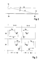
Fig. 2 zeigt den Radarsensor 10, der in einer bestimmten Einbauhöhe h oberhalb der Fahrbahnoberfläche 34 in das Fahrzeug eingebaut ist und Bodenclutter von einem bestimmten Punkt 36 auf der Fahrbahnoberfläche empfängt. Horizontal und in Fahrtrichtung des Fahrzeugs gemessen hat der Punkt 36 zum Radarsensor 10 den Abstand D. Der radiale, längs der Sichtlinie gemessene Abstand des Punktes 36 vom Radarsensor 10 ist mit d bezeichnet. Der Elevationswinkel des Punktes 36 vom Radarsensor 10 aus gesehen ist mit α bezeichnet. Es gilt folglich:
- Der Radarsensor 10 empfängt Bodenclutter nicht nur von dem einen Punkt 36, sondern von einer Vielzahl von Punkten, die in Fahrtrichtung auf der Fahrbahnoberfläche 34 verteilt sind. Für die hier anzustellenden Überlegungen kann jedoch vereinfachend der Bodenclutter als ein "normales" Objekt betrachtet werden, dessen Abstand und Relativgeschwindigkeit durch die Frequenzlage k des Maximums im Bodenclutter-Spektrum gegeben ist. Der Punkt 36 soll den Ort dieses fiktiven Objekts markieren. Wenn V die Eigengeschwindigkeit des Fahrzeugs ist, so gilt für die Relativgeschwindigkeit v des Punktes 36 relativ zum Radarsensor 10 (längs der Sichtlinie gemessen):

- Das Minuszeichen rührt daher, dass die Relativgeschwindigkeit bei zunehmendem Objektabstand positiv gezählt wird, während der Abstand d bei positiver Eigengeschwindigkeit V des Fahrzeugs abnimmt.
- Für die Frequenzlage k des Maximums im Bodenclutter gilt bei einem FMCW-Radar wie für jedes Objekt die Formel:

- Darin ist:
- F
- der Frequenzhub der Modulationsrampe
- f
- die Mittenfrequenz der betreffenden Modulationsrampe
- T
- die Dauer der Modulationsrampe
- Fa
- Frequenzhubanteil ((2/c) * F * h / sin α)
- Da
- Doppleranteil ((2/c) * f * T * V * cos α)
- Die Frequenzlage k ist hier eine dimensionslose Größe, die das sogenannte Frequenzbin angibt, in dem das Maximum des Bodenclutter-Spektrums liegt. Wenn der Mischer 14 ein IQ-Mischer ist, der die komplexe Amplitude des Zwischenfrequenzsignals liefert, so kann zwischen positiven und negativen Frequenzen unterschieden werden, und das Spektrum hat demgemäß einen positiven und einen negativen Teil. Wenn jedoch der Mischer 14 nur ein reelles Zwischenfrequenzsignal liefert, so tritt im Spektrum als unabhängige Variable nur der Betrag |k| der Frequenzlage auf.
- Mit Bezug auf
Fig. 3 soll jetzt einerseits für positive Eigengeschwindigkeiten des Fahrzeugs (V > 0) und andererseits für negative Eigengeschwindigkeiten des Fahrzeugs (V < 0) untersucht werden, wie sich die Frequenzlage k1 für die fallende Modulationsrampe 22 und die Frequenzlage k2 für die steigende Modulationsrampe 24 aus dem Frequenzhub- und Doppleranteilen Fa und Da zusammensetzen. - Für die fallende Modulationsrampe 22 ist der Frequenzhubanteil Fa stets negativ (Pfeil nach links in
Fig. 3 ), da der Frequenzhub F in Gleichung (1) negativ ist. Entsprechend ist für die steigende Modulationsrampe 24 der Frequenzhubanteil Fa stets positiv (Pfeil nach rechts). Bei positiver Eigengeschwindigkeit des Fahrzeugs (V > 0) ist der Doppleranteil Da stets positiv, bei negativer Eigengeschwindigkeit (V < 0) ist der Doppleranteil negativ. Bei Vorwärtsfahrt ist daher auf der fallenden Modulationsrampe 22 der Betrag von k1 gleich der Summe der Beträge von Fa und Da, auf der steigenden Modulationsrampe 24 hingegen gleich der Differenz dieser Beträge, und es gilt deshalb |k1| > |k2|. Bei Rückwärtsfahrt (V < 0) ist es hingegen umgekehrt, und des gilt |k1| < |k2|. So kann das Vergleichsmodul 32 einfach durch Vergleich der Beträge von k1 und k2 zwischen Vorwärtsfahrt und Rückwärtsfahrt unterscheiden. - Naturgemäß ist die Unterscheidung schwieriger, wenn die Eigengeschwindigkeit V des Fahrzeugs dem Betrage nach sehr klein ist. In der Praxis wird jedoch schon bei kleinen Fahrzeuggeschwindigkeiten in der Größenordnung von etwa 1 m/s eine hinreichend sichere Unterscheidung möglich. Als Beispiel illustriert
Fig. 4 die Abhängigkeit der Betragsdifferenz |k1| - |k2| von der Eigengeschwindigkeit V für eine typische Beispielkonfiguration, für welche die folgenden Parameter gelten: - |F| = 600 MHz
- T=5ms
- f = 76,5 GHz
- h = 0,35 m
- α = 10° (Maximum des Bodenclutters, abhängig vom vertikalen Antennendiagramm)
- Da für das Entscheidungssignal E nur die Absolutbeträge der Frequenzlagen k1 und k2 benötigt werden, ist das Verfahren auch mit Radarsensoren ausführbar, die keinen IQ-Mischer aufweisen.
- Ein alternatives Ausführungsbeispiel eines erfindungsgemäßen Radarsensors 10' ist in
Fig. 5 dargestellt. Das Steuergerät 18 dieses Radarsensors erhält von einem kostengünstigen Raddrehzahlsensor 38 ein Signal das (ggf. bis auf eine Proportionalitätskonstante) den Betrag |V| der Eigengeschwindigkeit V des Fahrzeugs angibt. Ein Berechnungsmodul 40 berechnet anhand dieses Signals zwei zu erwartende Bodenclutter-Spektren 42, 44, nämlich eines für die Annahme einer positiven Eigengeschwindigkeit (V > 0) und eines für die Annahme einer negativen Eigengeschwindigkeit (V < 0). Die Berechnung dieser Spektren basiert auf Gleichung (1) und berücksichtigt zusätzlich die durch das Antennendiagramm und die Abstandsdämpfung bedingte Intensitätsverteilung des Bodenclutters über den in Frage kommenden Bereich der Elevationswinkel α. Für eine (nach Betrag und Richtung) als fest angenommene Eigengeschwindigkeit V kann Gleichung (1) als Funktion betrachtet werden, die k in Abhängigkeit vom Winkel α angibt. Man kann deshalb das gesuchte Spektrum z.B. dadurch berechnen, dass man anhand des Antennendiagramms und der Abstandsdämpfung für jeden Elevationswinkel α die Intensität des empfangenen Radarsignals berechnet und dann anhand der Gleichung (1) die zugehörige Frequenzlage im Spektrum aufsucht und die Intensität dort einträgt. Zur Verminderung des Rechenaufwands können Spektren für verschiedene angenommene Eigengeschwindigkeiten vorab berechnet und in Tabellenform oder in geeignet parametrisierter Form in einem Speicher des Steuergerätes 18 hinterlegt werden. - In dem in
Fig. 5 gezeigten Beispiel werden nur die Spektren für eine Modulationsrampe berechnet. - Ein Vergleichsmodul 32' ist in diesem Fall so ausgebildet, dass es die berechneten Spektren 42 und 44 nacheinander mit dem im Verarbeitungsmodul 26 aufgenommenen Spektrum 30' vergleicht, dass den tatsächlich vom Radarsensor empfangenen Bodenclutter repräsentiert. Für den Vergleich kann irgendein geeignetes Abstandsmaß für Funktionen benutzt werden, beispielsweise das Integral über das Quadrat der Differenz der zu vergleichenden Funktionen. Bei diesem Vergleich wird dasjenige der beiden Spektren 42, 44, das der tatsächlichen Fahrtrichtung des Fahrzeugs entspricht, am besten mit dem gemessenen Spektrum 30' übereinstimmen. Das wird in der Regel auch dann gelten, wenn in das gemessene Spektrum zusätzlich Objektpeaks aufweist. Je nach geforderter Genauigkeit kann deshalb u. U. ein Ausfiltern der Objektpeaks aus dem Bodenclutter-Spektrum unterbleiben.
- Mit dem Vergleichsmodul 32' ist auch eine Qualitätsprüfung in dem Sinne möglich, dass das Entscheidungssignal E nur dann als gültig angesehen wird, wenn der Abstand zwischen einem der beiden Spektren 42, 44 und dem gemessenen Spektrum 22' unterhalb eines vorgegebenen Schwellenwertes liegt. Wenn der Abstand für keines der Spektren 42, 44 unter dem Schwellenwert liegt, kann ein Fehlersignal ausgegeben werden.
- Wenn sich die Fahrtrichtung des Fahrzeugs ändert, also bei einem Wechsel von Vorwärtsfahrt auf Rückwärtsfahrt oder umgekehrt, muss das vom Raddrehzahlsensor 38 gelieferte Signal |V| zu irgendeinem Zeitpunkt praktisch den Wert null annehmen. Solange |V| oberhalb eines bestimmten Schwellenwertes bleibt, kann deshalb für die Unterscheidung zwischen Vorwärtsfahrt und Rückwärtsfahrt das vorher erzeugte Entscheidungssignal E benutzt werden, ohne dass eine Neuberechnung erforderlich ist. Ein möglicher Ablauf ist in
Fig. 6 in einem Flussdiagramm dargestellt. - In Schritt S1 wird geprüft, ob der Betrag |V| der Eigengeschwindigkeit größer als der vorgegebene Schwellenwert Vmin ist. Wenn das der Fall ist (J), wird in Schritt S2 geprüft, ob ein Richtungsflag gesetzt ist. Wenn das der Fall ist (J), erfolgt ein Rücksprung zu Schritt S1 und es beginnt ein neuer Programmzyklus. Wenn kein Richtungsflag gesetzt ist (N), wird mit Hilfe des Entscheidungsmoduls 32' ein neues Entscheidungssignal E generiert. In Schritt S3 wird zunächst geprüft, ob eine hinreichende Übereinstimmung zwischen einem der Spektren 42, 44 und dem gemessenen Spektrum 22' erreicht werden konnte. Wenn das der Fall ist (J), wird in Schritt S4 das Richtungsflag anhand des Entscheidungssignals E entweder auf Vorwärtsfahrt oder auf Rückwärtsfahrt gesetzt, und anschließend erfolgt ein Rücksprung zu Schritt S1. Wenn in Schritt S3 die Fahrtrichtung nicht zuverlässig erkannt werden konnte (N), so wird in Schritt S5 eine Fehlerbehandlung durchgeführt. Diese Fehlerbehandlung kann beispielsweise darin bestehen, dass die kumulierte Häufigkeit von fehlgeschlagenen Richtungserkennungen aktualisiert wird, und wenn die Häufigkeit von Fehlern einen bestimmten Schwellenwert überschreitet, ein Fehlersignal ausgegeben wird. Nach der Fehlerbehandlung erfolgt wieder ein Rücksprung zu Schritt S1.
- Wenn in Schritt S1 festgestellt wird, dass der Betrag der Eigengeschwindigkeit unter den Minimalwert Vmin abgenommen hat (M), so wird in Schritt S6 das Richtungsflag gelöscht, und es erfolgt ein Rücksprung zu Schritt S1. Ein neues Richtungsflag wird erst dann gesetzt, wenn der Betrag der Eigengeschwindigkeit wieder über Vmin zugenommen hat.
Claims (6)
- Verfahren zur Unterscheidung zwischen Vorwärtsfahrt und Rückwärtsfahrt bei einem Fahrzeug, das einen Radarsensor (10; 10') aufweist, dadurch gekennzeichnet, dass die Unterscheidung anhand einer charakteristischen Signatur eines von dem Radarsensor (10; 10') empfangenen Signals vorgenommen wird.
- Verfahren nach Anspruch 1, bei dem eine charakteristische Signatur eines Bodenclutter-Signals ausgewertet wird.
- Verfahren nach Anspruch 2, bei dem als Radarsensor (10; 10') ein FMCW-Radar verwendet wird.
- Verfahren nach Anspruch 3, bei dem als charakteristische Signatur die Frequenzlage (k1, k2) des Maximums im Spektrum (28, 30) des Bodencutters für mindestens eine fallende Modulationsrampe (22) und mindestens eine steigende Modulationsrampe (44) aufgesucht wird und die Frequenzlagen (k1, k2) für diese beiden Modulationsrampen miteinander verglichen werden.
- Verfahren nach Anspruch 3, mit den folgenden Schritten:- Empfangen eines Signals (|V|) eines Drehzahlsensors (38) und Berechnen des Betrages der Eigengeschwindigkeit (V) des Fahrzeugs aus diesem Signal,- Berechnen eines erwarteten Bodenclutter-Spektrums (42) anhand des Betrages der Eigengeschwindigkeit (V) unter Annahme von Vorwärtsfahrt,- Berechnen eines erwarten Bodenclutter-Spektrums (44) anhand des Betrages der Eigengeschwindigkeit (V) unter Annahme von Rückwärtsfahrt,- Vergleich der beiden erwarteten Spektren (42, 44) mit dem tatsächlich vom Radarsensor (10') gemessenen Bodenclutter-Spektrum (30').
- Radarsensor für Kraftfahrzeuge, gekennzeichnet durch ein Steuergerät (18), das zur Ausführung des Verfahrens nach einem der Ansprüche 1 bis 5 ausgebildet ist.
Applications Claiming Priority (1)
| Application Number | Priority Date | Filing Date | Title |
|---|---|---|---|
| DE102011078989A DE102011078989A1 (de) | 2011-07-12 | 2011-07-12 | Verfahren und Radarsensor zur Unterscheidung zwischen Vorwärtsfahrt und Rückwärtsfahrt bei einem Fahrzeug |
Publications (2)
| Publication Number | Publication Date |
|---|---|
| EP2546677A1 true EP2546677A1 (de) | 2013-01-16 |
| EP2546677B1 EP2546677B1 (de) | 2017-07-12 |
Family
ID=46084930
Family Applications (1)
| Application Number | Title | Priority Date | Filing Date |
|---|---|---|---|
| EP12168296.7A Not-in-force EP2546677B1 (de) | 2011-07-12 | 2012-05-16 | Verfahren und Radarsensor zur Unterscheidung zwischen Vorwärtsfahrt und Rückwärtsfahrt bei einem Fahrzeug |
Country Status (2)
| Country | Link |
|---|---|
| EP (1) | EP2546677B1 (de) |
| DE (1) | DE102011078989A1 (de) |
Citations (4)
| Publication number | Priority date | Publication date | Assignee | Title |
|---|---|---|---|---|
| US3974500A (en) * | 1975-01-13 | 1976-08-10 | The Singer Company | Velocity sensing apparatus |
| US4635059A (en) * | 1982-05-25 | 1987-01-06 | Plessey Overseas Limited | Vehicle mounted Doppler radar system |
| DE4042494C2 (de) * | 1990-03-08 | 1998-10-29 | Conner Joe Scott O | Vorrichtung in einem Fahrzeug zur Anzeige von Relativgeschwindigkeiten zu anderen Fahrzeugen |
| DE102008008385A1 (de) * | 2008-02-09 | 2009-08-13 | Adc Automotive Distance Control Systems Gmbh | Verfahren zur Bestimmung der Geschwindigkeit für ein Strahlsensorsystem |
Family Cites Families (1)
| Publication number | Priority date | Publication date | Assignee | Title |
|---|---|---|---|---|
| EP0963562B1 (de) * | 1997-02-28 | 2002-08-14 | Siemens Aktiengesellschaft | Verfahren zur bestimmung einer bewegungsrichtung |
-
2011
- 2011-07-12 DE DE102011078989A patent/DE102011078989A1/de not_active Ceased
-
2012
- 2012-05-16 EP EP12168296.7A patent/EP2546677B1/de not_active Not-in-force
Patent Citations (4)
| Publication number | Priority date | Publication date | Assignee | Title |
|---|---|---|---|---|
| US3974500A (en) * | 1975-01-13 | 1976-08-10 | The Singer Company | Velocity sensing apparatus |
| US4635059A (en) * | 1982-05-25 | 1987-01-06 | Plessey Overseas Limited | Vehicle mounted Doppler radar system |
| DE4042494C2 (de) * | 1990-03-08 | 1998-10-29 | Conner Joe Scott O | Vorrichtung in einem Fahrzeug zur Anzeige von Relativgeschwindigkeiten zu anderen Fahrzeugen |
| DE102008008385A1 (de) * | 2008-02-09 | 2009-08-13 | Adc Automotive Distance Control Systems Gmbh | Verfahren zur Bestimmung der Geschwindigkeit für ein Strahlsensorsystem |
Non-Patent Citations (1)
| Title |
|---|
| MICHAEL WOLLITZER ET AL: "Multifunctional Radar Sensor for Automotive Application", IEEE TRANSACTIONS ON MICROWAVE THEORY AND TECHNIQUES, IEEE SERVICE CENTER, PISCATAWAY, NJ, US, vol. 46, no. 5, 1 May 1998 (1998-05-01), XP011037173, ISSN: 0018-9480 * |
Also Published As
| Publication number | Publication date |
|---|---|
| EP2546677B1 (de) | 2017-07-12 |
| DE102011078989A1 (de) | 2013-01-17 |
Similar Documents
| Publication | Publication Date | Title |
|---|---|---|
| EP3175256B1 (de) | Verfahren zum klassifizieren eines objektes in einem umgebungsbereich eines kraftfahrzeugs, fahrerassistenzsystem und kraftfahrzeug | |
| EP2667219B1 (de) | Detektion von Radarobjekten mit einem Radarsensor eines Kraftfahrzeugs | |
| EP2507649B1 (de) | Verfahren zum eindeutigen bestimmen einer entfernung und/oder einer relativen geschwindigkeit eines objektes, fahrerassistenzeinrichtung und kraftfahrzeug | |
| DE102017123969B4 (de) | Verfahren zur Klassifikation von flächigen Strukturen | |
| EP1864155B1 (de) | Verfahren und vorrichtung zur abstands- und relativgeschwindigkeitsmessung mehrerer objekte | |
| EP2549289A2 (de) | Erkennung einer Dejustage eines Radarsensors eines Fahrzeugs | |
| DE102010064348A1 (de) | Radarsensor für Kraftfahrzeuge | |
| EP2401630B1 (de) | Verfahren zur erkennung von vereisung bei einem winkelauflösenden radarsensor in einem fahrerassistenzsystem für kraftfahrzeuge | |
| DE102009001265A1 (de) | Radarsensor mit Blinheitserkennungseinrichtung | |
| EP3752852B1 (de) | Schätzung von kartesischen geschwindigkeiten von ausgedehnten radarobjekten mit einem radarsensor | |
| WO2015197229A1 (de) | Verfahren zur objektortung mit einem fmcw-radar | |
| DE102009000472A1 (de) | Verfahren zur Detektion von Niederschlag mit einem Radarortungsgerät für Kraftfahrzeuge | |
| EP2778714A1 (de) | Verfahren zur Erfassung von Verkehrsverstößen in einem Ampelbereich durch Heckanmessung mit einem Radargerät | |
| EP3752851B1 (de) | Schätzung von quergeschwindigkeiten oder kartesischen geschwindigkeiten von punktzielen mit einem radarsensor | |
| DE102009000469A1 (de) | Verfahren zur Detektion von Niederschlag mit einem Radarortungsgerät für Kraftfahrzeuge | |
| DE102007020264A1 (de) | Verfahren und Messvorrichtung zum Bestimmen einer Relativgeschwindigkeit | |
| WO2016050629A1 (de) | Radarsensor | |
| EP3374791A1 (de) | Seitliche leitplankenerkennung über einen abstandssensor im kfz | |
| DE102011121560A1 (de) | Verfahren zur Detektion und Klassifikation von Objekten | |
| DE102018217533A1 (de) | Verfahren zur Klassifikation eines Objekts | |
| DE19754220B4 (de) | Verfahren und Vorrichtung zur Erkennung einer bevorstehenden oder möglichen Kollision | |
| DE102014114110A1 (de) | Radarsensor | |
| DE102007058241B4 (de) | Auswerteverfahren, insbesondere für ein Fahrerassistenzsystem eines Kraftfahrzeugs, zur Objektdetektion mittels eines Radarsensors | |
| EP2546677B1 (de) | Verfahren und Radarsensor zur Unterscheidung zwischen Vorwärtsfahrt und Rückwärtsfahrt bei einem Fahrzeug | |
| DE102020110029A1 (de) | Verfahren zum Betreiben eines Radarsensors, Radarsystem mit wenigstens einem Radarsensor und Fahrzeug mit wenigstens einem Radarsystem |
Legal Events
| Date | Code | Title | Description |
|---|---|---|---|
| PUAI | Public reference made under article 153(3) epc to a published international application that has entered the european phase |
Free format text: ORIGINAL CODE: 0009012 |
|
| AK | Designated contracting states |
Kind code of ref document: A1 Designated state(s): AL AT BE BG CH CY CZ DE DK EE ES FI FR GB GR HR HU IE IS IT LI LT LU LV MC MK MT NL NO PL PT RO RS SE SI SK SM TR |
|
| AX | Request for extension of the european patent |
Extension state: BA ME |
|
| 17P | Request for examination filed |
Effective date: 20130716 |
|
| RBV | Designated contracting states (corrected) |
Designated state(s): AL AT BE BG CH CY CZ DE DK EE ES FI FR GB GR HR HU IE IS IT LI LT LU LV MC MK MT NL NO PL PT RO RS SE SI SK SM TR |
|
| 17Q | First examination report despatched |
Effective date: 20150601 |
|
| GRAP | Despatch of communication of intention to grant a patent |
Free format text: ORIGINAL CODE: EPIDOSNIGR1 |
|
| INTG | Intention to grant announced |
Effective date: 20170317 |
|
| GRAS | Grant fee paid |
Free format text: ORIGINAL CODE: EPIDOSNIGR3 |
|
| GRAA | (expected) grant |
Free format text: ORIGINAL CODE: 0009210 |
|
| AK | Designated contracting states |
Kind code of ref document: B1 Designated state(s): AL AT BE BG CH CY CZ DE DK EE ES FI FR GB GR HR HU IE IS IT LI LT LU LV MC MK MT NL NO PL PT RO RS SE SI SK SM TR |
|
| REG | Reference to a national code |
Ref country code: GB Ref legal event code: FG4D Free format text: NOT ENGLISH |
|
| REG | Reference to a national code |
Ref country code: CH Ref legal event code: EP |
|
| REG | Reference to a national code |
Ref country code: AT Ref legal event code: REF Ref document number: 908863 Country of ref document: AT Kind code of ref document: T Effective date: 20170715 |
|
| REG | Reference to a national code |
Ref country code: IE Ref legal event code: FG4D Free format text: LANGUAGE OF EP DOCUMENT: GERMAN |
|
| REG | Reference to a national code |
Ref country code: DE Ref legal event code: R096 Ref document number: 502012010728 Country of ref document: DE |
|
| REG | Reference to a national code |
Ref country code: NL Ref legal event code: MP Effective date: 20170712 |
|
| REG | Reference to a national code |
Ref country code: LT Ref legal event code: MG4D |
|
| PG25 | Lapsed in a contracting state [announced via postgrant information from national office to epo] |
Ref country code: NO Free format text: LAPSE BECAUSE OF FAILURE TO SUBMIT A TRANSLATION OF THE DESCRIPTION OR TO PAY THE FEE WITHIN THE PRESCRIBED TIME-LIMIT Effective date: 20171012 Ref country code: SE Free format text: LAPSE BECAUSE OF FAILURE TO SUBMIT A TRANSLATION OF THE DESCRIPTION OR TO PAY THE FEE WITHIN THE PRESCRIBED TIME-LIMIT Effective date: 20170712 Ref country code: HR Free format text: LAPSE BECAUSE OF FAILURE TO SUBMIT A TRANSLATION OF THE DESCRIPTION OR TO PAY THE FEE WITHIN THE PRESCRIBED TIME-LIMIT Effective date: 20170712 Ref country code: FI Free format text: LAPSE BECAUSE OF FAILURE TO SUBMIT A TRANSLATION OF THE DESCRIPTION OR TO PAY THE FEE WITHIN THE PRESCRIBED TIME-LIMIT Effective date: 20170712 Ref country code: LT Free format text: LAPSE BECAUSE OF FAILURE TO SUBMIT A TRANSLATION OF THE DESCRIPTION OR TO PAY THE FEE WITHIN THE PRESCRIBED TIME-LIMIT Effective date: 20170712 Ref country code: NL Free format text: LAPSE BECAUSE OF FAILURE TO SUBMIT A TRANSLATION OF THE DESCRIPTION OR TO PAY THE FEE WITHIN THE PRESCRIBED TIME-LIMIT Effective date: 20170712 |
|
| PG25 | Lapsed in a contracting state [announced via postgrant information from national office to epo] |
Ref country code: LV Free format text: LAPSE BECAUSE OF FAILURE TO SUBMIT A TRANSLATION OF THE DESCRIPTION OR TO PAY THE FEE WITHIN THE PRESCRIBED TIME-LIMIT Effective date: 20170712 Ref country code: IS Free format text: LAPSE BECAUSE OF FAILURE TO SUBMIT A TRANSLATION OF THE DESCRIPTION OR TO PAY THE FEE WITHIN THE PRESCRIBED TIME-LIMIT Effective date: 20171112 Ref country code: GR Free format text: LAPSE BECAUSE OF FAILURE TO SUBMIT A TRANSLATION OF THE DESCRIPTION OR TO PAY THE FEE WITHIN THE PRESCRIBED TIME-LIMIT Effective date: 20171013 Ref country code: RS Free format text: LAPSE BECAUSE OF FAILURE TO SUBMIT A TRANSLATION OF THE DESCRIPTION OR TO PAY THE FEE WITHIN THE PRESCRIBED TIME-LIMIT Effective date: 20170712 Ref country code: BG Free format text: LAPSE BECAUSE OF FAILURE TO SUBMIT A TRANSLATION OF THE DESCRIPTION OR TO PAY THE FEE WITHIN THE PRESCRIBED TIME-LIMIT Effective date: 20171012 Ref country code: ES Free format text: LAPSE BECAUSE OF FAILURE TO SUBMIT A TRANSLATION OF THE DESCRIPTION OR TO PAY THE FEE WITHIN THE PRESCRIBED TIME-LIMIT Effective date: 20170712 Ref country code: PL Free format text: LAPSE BECAUSE OF FAILURE TO SUBMIT A TRANSLATION OF THE DESCRIPTION OR TO PAY THE FEE WITHIN THE PRESCRIBED TIME-LIMIT Effective date: 20170712 |
|
| REG | Reference to a national code |
Ref country code: DE Ref legal event code: R097 Ref document number: 502012010728 Country of ref document: DE |
|
| PG25 | Lapsed in a contracting state [announced via postgrant information from national office to epo] |
Ref country code: RO Free format text: LAPSE BECAUSE OF FAILURE TO SUBMIT A TRANSLATION OF THE DESCRIPTION OR TO PAY THE FEE WITHIN THE PRESCRIBED TIME-LIMIT Effective date: 20170712 Ref country code: CZ Free format text: LAPSE BECAUSE OF FAILURE TO SUBMIT A TRANSLATION OF THE DESCRIPTION OR TO PAY THE FEE WITHIN THE PRESCRIBED TIME-LIMIT Effective date: 20170712 Ref country code: DK Free format text: LAPSE BECAUSE OF FAILURE TO SUBMIT A TRANSLATION OF THE DESCRIPTION OR TO PAY THE FEE WITHIN THE PRESCRIBED TIME-LIMIT Effective date: 20170712 |
|
| PLBE | No opposition filed within time limit |
Free format text: ORIGINAL CODE: 0009261 |
|
| STAA | Information on the status of an ep patent application or granted ep patent |
Free format text: STATUS: NO OPPOSITION FILED WITHIN TIME LIMIT |
|
| REG | Reference to a national code |
Ref country code: FR Ref legal event code: PLFP Year of fee payment: 7 |
|
| PG25 | Lapsed in a contracting state [announced via postgrant information from national office to epo] |
Ref country code: SK Free format text: LAPSE BECAUSE OF FAILURE TO SUBMIT A TRANSLATION OF THE DESCRIPTION OR TO PAY THE FEE WITHIN THE PRESCRIBED TIME-LIMIT Effective date: 20170712 Ref country code: IT Free format text: LAPSE BECAUSE OF FAILURE TO SUBMIT A TRANSLATION OF THE DESCRIPTION OR TO PAY THE FEE WITHIN THE PRESCRIBED TIME-LIMIT Effective date: 20170712 Ref country code: SM Free format text: LAPSE BECAUSE OF FAILURE TO SUBMIT A TRANSLATION OF THE DESCRIPTION OR TO PAY THE FEE WITHIN THE PRESCRIBED TIME-LIMIT Effective date: 20170712 Ref country code: EE Free format text: LAPSE BECAUSE OF FAILURE TO SUBMIT A TRANSLATION OF THE DESCRIPTION OR TO PAY THE FEE WITHIN THE PRESCRIBED TIME-LIMIT Effective date: 20170712 |
|
| 26N | No opposition filed |
Effective date: 20180413 |
|
| PG25 | Lapsed in a contracting state [announced via postgrant information from national office to epo] |
Ref country code: SI Free format text: LAPSE BECAUSE OF FAILURE TO SUBMIT A TRANSLATION OF THE DESCRIPTION OR TO PAY THE FEE WITHIN THE PRESCRIBED TIME-LIMIT Effective date: 20170712 |
|
| PG25 | Lapsed in a contracting state [announced via postgrant information from national office to epo] |
Ref country code: MT Free format text: LAPSE BECAUSE OF FAILURE TO SUBMIT A TRANSLATION OF THE DESCRIPTION OR TO PAY THE FEE WITHIN THE PRESCRIBED TIME-LIMIT Effective date: 20170712 |
|
| REG | Reference to a national code |
Ref country code: CH Ref legal event code: PL |
|
| GBPC | Gb: european patent ceased through non-payment of renewal fee |
Effective date: 20180516 |
|
| REG | Reference to a national code |
Ref country code: BE Ref legal event code: MM Effective date: 20180531 |
|
| PG25 | Lapsed in a contracting state [announced via postgrant information from national office to epo] |
Ref country code: MC Free format text: LAPSE BECAUSE OF FAILURE TO SUBMIT A TRANSLATION OF THE DESCRIPTION OR TO PAY THE FEE WITHIN THE PRESCRIBED TIME-LIMIT Effective date: 20170712 |
|
| REG | Reference to a national code |
Ref country code: IE Ref legal event code: MM4A |
|
| PG25 | Lapsed in a contracting state [announced via postgrant information from national office to epo] |
Ref country code: CH Free format text: LAPSE BECAUSE OF NON-PAYMENT OF DUE FEES Effective date: 20180531 Ref country code: LI Free format text: LAPSE BECAUSE OF NON-PAYMENT OF DUE FEES Effective date: 20180531 |
|
| PG25 | Lapsed in a contracting state [announced via postgrant information from national office to epo] |
Ref country code: LU Free format text: LAPSE BECAUSE OF NON-PAYMENT OF DUE FEES Effective date: 20180516 |
|
| PG25 | Lapsed in a contracting state [announced via postgrant information from national office to epo] |
Ref country code: GB Free format text: LAPSE BECAUSE OF NON-PAYMENT OF DUE FEES Effective date: 20180516 Ref country code: IE Free format text: LAPSE BECAUSE OF NON-PAYMENT OF DUE FEES Effective date: 20180516 |
|
| PG25 | Lapsed in a contracting state [announced via postgrant information from national office to epo] |
Ref country code: BE Free format text: LAPSE BECAUSE OF NON-PAYMENT OF DUE FEES Effective date: 20180531 |
|
| REG | Reference to a national code |
Ref country code: AT Ref legal event code: MM01 Ref document number: 908863 Country of ref document: AT Kind code of ref document: T Effective date: 20180516 |
|
| PGFP | Annual fee paid to national office [announced via postgrant information from national office to epo] |
Ref country code: FR Payment date: 20190521 Year of fee payment: 8 |
|
| PG25 | Lapsed in a contracting state [announced via postgrant information from national office to epo] |
Ref country code: AT Free format text: LAPSE BECAUSE OF NON-PAYMENT OF DUE FEES Effective date: 20180516 |
|
| PG25 | Lapsed in a contracting state [announced via postgrant information from national office to epo] |
Ref country code: TR Free format text: LAPSE BECAUSE OF FAILURE TO SUBMIT A TRANSLATION OF THE DESCRIPTION OR TO PAY THE FEE WITHIN THE PRESCRIBED TIME-LIMIT Effective date: 20170712 |
|
| PG25 | Lapsed in a contracting state [announced via postgrant information from national office to epo] |
Ref country code: PT Free format text: LAPSE BECAUSE OF FAILURE TO SUBMIT A TRANSLATION OF THE DESCRIPTION OR TO PAY THE FEE WITHIN THE PRESCRIBED TIME-LIMIT Effective date: 20170712 Ref country code: HU Free format text: LAPSE BECAUSE OF FAILURE TO SUBMIT A TRANSLATION OF THE DESCRIPTION OR TO PAY THE FEE WITHIN THE PRESCRIBED TIME-LIMIT; INVALID AB INITIO Effective date: 20120516 |
|
| PG25 | Lapsed in a contracting state [announced via postgrant information from national office to epo] |
Ref country code: MK Free format text: LAPSE BECAUSE OF NON-PAYMENT OF DUE FEES Effective date: 20170712 Ref country code: CY Free format text: LAPSE BECAUSE OF FAILURE TO SUBMIT A TRANSLATION OF THE DESCRIPTION OR TO PAY THE FEE WITHIN THE PRESCRIBED TIME-LIMIT Effective date: 20170712 |
|
| PG25 | Lapsed in a contracting state [announced via postgrant information from national office to epo] |
Ref country code: AL Free format text: LAPSE BECAUSE OF FAILURE TO SUBMIT A TRANSLATION OF THE DESCRIPTION OR TO PAY THE FEE WITHIN THE PRESCRIBED TIME-LIMIT Effective date: 20170712 |
|
| PG25 | Lapsed in a contracting state [announced via postgrant information from national office to epo] |
Ref country code: FR Free format text: LAPSE BECAUSE OF NON-PAYMENT OF DUE FEES Effective date: 20200531 |
|
| PGFP | Annual fee paid to national office [announced via postgrant information from national office to epo] |
Ref country code: DE Payment date: 20210723 Year of fee payment: 10 |
|
| REG | Reference to a national code |
Ref country code: DE Ref legal event code: R119 Ref document number: 502012010728 Country of ref document: DE |
|
| PG25 | Lapsed in a contracting state [announced via postgrant information from national office to epo] |
Ref country code: DE Free format text: LAPSE BECAUSE OF NON-PAYMENT OF DUE FEES Effective date: 20221201 |