EP2546781A2 - Procédé et système dýidentification de champs dýéclairage dans une image - Google Patents
Procédé et système dýidentification de champs dýéclairage dans une image Download PDFInfo
- Publication number
- EP2546781A2 EP2546781A2 EP12173037A EP12173037A EP2546781A2 EP 2546781 A2 EP2546781 A2 EP 2546781A2 EP 12173037 A EP12173037 A EP 12173037A EP 12173037 A EP12173037 A EP 12173037A EP 2546781 A2 EP2546781 A2 EP 2546781A2
- Authority
- EP
- European Patent Office
- Prior art keywords
- image
- tokens
- color
- illumination
- token
- Prior art date
- Legal status (The legal status is an assumption and is not a legal conclusion. Google has not performed a legal analysis and makes no representation as to the accuracy of the status listed.)
- Granted
Links
Images





Classifications
-
- G—PHYSICS
- G06—COMPUTING OR CALCULATING; COUNTING
- G06T—IMAGE DATA PROCESSING OR GENERATION, IN GENERAL
- G06T7/00—Image analysis
- G06T7/10—Segmentation; Edge detection
- G06T7/12—Edge-based segmentation
-
- G—PHYSICS
- G06—COMPUTING OR CALCULATING; COUNTING
- G06T—IMAGE DATA PROCESSING OR GENERATION, IN GENERAL
- G06T7/00—Image analysis
- G06T7/90—Determination of colour characteristics
-
- G—PHYSICS
- G06—COMPUTING OR CALCULATING; COUNTING
- G06V—IMAGE OR VIDEO RECOGNITION OR UNDERSTANDING
- G06V10/00—Arrangements for image or video recognition or understanding
- G06V10/40—Extraction of image or video features
- G06V10/60—Extraction of image or video features relating to illumination properties, e.g. using a reflectance or lighting model
-
- G—PHYSICS
- G06—COMPUTING OR CALCULATING; COUNTING
- G06T—IMAGE DATA PROCESSING OR GENERATION, IN GENERAL
- G06T2207/00—Indexing scheme for image analysis or image enhancement
- G06T2207/10—Image acquisition modality
- G06T2207/10024—Color image
Definitions
- the present invention provides a method and system comprising image techniques that accurately and correctly reflect and represent physical phenomena occurring in the visual world, for identification of illumination fields in an image.
- an automated, computerized method for determining an illumination field in an image.
- the method comprises the steps of identifying linear tokens in the image and utilizing the linear tokens to identify an illumination field.
- an automated, computerized method for determining shadow/lit pixels of an image.
- the method comprises the steps of identifying uniform tokens in the image and utilizing the uniform tokens to identify shadow/lit pixels of the image.
- an automated, computerized method for determining a shadow in an image.
- the method comprises the steps of calculating a characteristic spectral ratio for the image, and utilizing the characteristic spectral ratio to identify a shadow in the image.
- an automated, computerized method for determining a material edge in an image.
- the method comprises the steps of calculating an illumination gradient for the image and utilizing the illumination gradient to identify a material edge in the image.
- an automated, computerized method for determining an illumination field in an image.
- the method comprises the steps of identifying tokens in the image, clustering the identified tokens into groups and utilizing the token groups to identify an illumination field.
- computer systems which include one or more computers configured (e.g., programmed) to perform the methods described above.
- computer readable media are provided which have stored thereon computer executable process steps operable to control a computer(s) to implement the embodiments described above.
- the automated, computerized methods can be performed by a digital computer, analog computer, optical sensor, state machine, sequencer or any device or apparatus that can be designed or programed to carry out the steps of the methods of the present invention.
- Figure 1 is a block diagram of a computer system arranged and configured to perform operations related to images.
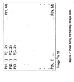
- Figure 2 shows an n X m pixel array image file for an image stored in the computer system of figure 1 .
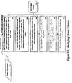
- Figure 3a is a flow chart for identifying linear tokens in an image according to a feature of the present invention.
- Figure 3b shows an image at a material boundary, and pixel values at the boundary.
- Figure 4 is a graph in RGB color space showing colors for a material, from a fully shaded color value to a fully lit color value, as determined by execution of a simplified bi-illuminant dichromatic reflection model according to a feature of the present invention.
- Figures 5a & b are graphs in RGB color space showing colors for a material, from a fully shaded color value to a fully lit color value, with error bounds forming a cylinder, as determined by execution of the bi-illuminant dichromatic reflection model according to a feature of the present invention.
- Figure 6 is a flow chart for using token groups to identify regions of consistent reflectance of an image, according to a feature of the present invention.
- Figure 7 is a flow chart for using linear tokens to identify regions of consistent reflectance of an image, according to a feature of the present invention.
- Figure 8 is a flow chart for using Nth order tokens to identify shadowed and lit regions of an image, according to a feature of the present invention.
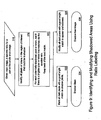
- Figure 9 is a flow chart for using ratio labeling to identify and correct shadowed areas of an image, according to a feature of the present invention.
- Figure 10 is a flow chart for identifying illumination gradients in an image, according to a feature of the present invention.
- Figure 11 is a flow chart for identifying material edges in an image using illumination gradients, according to a feature of the present invention.
- FIG. 1 there is shown a block diagram of a computer system 10 arranged and configured to perform operations related to images.
- a CPU 12 is coupled to a device such as, for example, a digital camera 14 via, for example, a USB port.
- the digital camera 14 operates to download images stored locally on the camera 14, to the CPU 12.
- the CPU 12 stores the downloaded images in a memory 16 as image files 18.
- the image files 18 can be accessed by the CPU 12 for display on a monitor 20, or for print out on a printer 22.
- the CPU can be implemented as a microprocessor embedded in a device such as, for example, the digital camera 14 or a robot.
- the CPU can also be equipped with a real time operating system for real time operations relating to images, for example, in connection with a robotic operation or an interactive operation with a user.
- each image file 18 comprises an n X m pixel array.
- Each pixel, p is a picture element corresponding to a discrete portion of the overall image. All of the pixels together define the image represented by the image file 18.
- Each pixel comprises a digital value corresponding to a set of color bands, for example, red, green and blue color components (RGB) of the picture element.
- RGB red, green and blue color components
- the present invention is applicable to any multi-band image, where each band corresponds to a piece of the electro-magnetic spectrum.
- the present invention can also be utilized in connection with a grayscale image (a single band).
- the pixel array includes m columns of n rows each, starting with the pixel p (1,1) and ending with the pixel p(n, m).
- the CPU 12 retrieves the corresponding image file 18 from the memory 16, and operates the monitor 20 or printer 22, as the case may be, as a function of the digital values of the pixels in the image file 18, as is generally known.
- the CPU 12 operates to analyze the RGB values of the pixels of a stored image file 18 to achieve various objectives, such as, for example, identification of regions of consistent reflectance within an image, to identify a single material of an object.
- an image comprises two components, material and illumination. All changes in an image are caused by one or the other of these components.
- What is visible to the human eye upon display on the monitor 20 of a stored image file 18 by the CPU 12, is the pixel color values caused by the interaction between specular and body reflection properties of material objects in, for example, a scene photographed by the digital camera 14 and illumination flux within an illumination field present at the time the photograph was taken.
- the illumination flux comprises an ambient illuminant and an incident illuminant.
- the incident illuminant is light that causes a shadow and is found outside a shadow perimeter.
- the ambient illuminant is light present on both the bright and dark sides of a shadow, but is more perceptible within the dark region.
- the computer system 10 can be operated to differentiate between material aspects and illumination flux through recognition of a spectral shift caused by an interplay between the incident or direct illuminant and the ambient illuminant in the illumination field.
- a spectral shift caused by an interplay between the incident or direct illuminant and the ambient illuminant in the illumination field When one of material and illumination is known in an image, the other can be readily deduced.
- the spectrum for the incident illuminant and the ambient illuminant can be different from one another. Indeed, the spectrum of the ambient illuminant may change throughout the scene due to interreflection effects. In the absence of interreflection, a spectral shift caused by a shadow, i.e., a decrease of the intensity of the incident illuminant, will be invariant over different materials present in a scene depicted in an image.
- a token analysis can be used to identify areas of consistent reflectance within an image, to thereby identify a single material of an object.
- a linear token is a nonhomogeneous token comprising a connected region of the image wherein adjacent pixels of the region have differing color measurement values that fall within a cylinder in RGB space, from a dark end (in shadow) to a bright end (lit end), along a positive slope.
- the cylinder configuration is predicted by a bi-illuminant dichromatic reflection model (BIDR model), according to a feature of the present invention, when the color change is due to an illumination change forming a shadow (i.e.
- ⁇ b is the product of a shadow factor s x , y, z and a geometric factor mb ( ⁇ i), and M a ( ⁇ ) is the integral of the ambient illuminant and geometric body reflectance over a hemisphere, excluding the incident illuminant.
- step 100 the CPU 12 is given an image file 18, for processing.
- the CPU 12 tests each pixel in the image for identification of linear tokens.
- step 102 for a current pixel, the CPU 12 tests a local area around the current pixel to determine whether the current pixel and its neighboring pixels fall within a linear segment or cylinder in RGB space (BIDR cylinder), as predicted by the BIDR model.
- BIDR cylinder RGB space
- the BIDR model predicts that all of the measured colors of a particular material in shadow, light and penumbra extend along a line in RGB space (the cube shown in figure 4 ).
- a camera or other sensor used to record an image typically has noise, and no material in an image is of a completely uniform color. Accordingly, the appearance values of the surface fall within a cylinder having a width determined by variation in material and imaging sensor noise characteristics.
- the cylinder representing body reflection according to the incident and ambient illuminants considered in the BIDR model of the present invention, has a unique starting place for every intrinsic color in the scene. The starting point is determined by the product of the ambient illumination and the body color, and the slope of the cylinder in RGB space is determined by the product of the incident illumination and the body color.
- Figures 5a & b are graphs in RGB color space showing colors for a material, from a fully shaded color value to a fully lit color value, with error bounds forming a cylinder.
- a cylinder is shown around the RGB line predicted by the BIDR model, with the dimensions of the cylinder diameter being a function of the noise of the recording device used to record the image, and variations.
- the color shifted from a distinctly blue color to a distinctly red color, while at the lit end the color remains blue.
- an adjustment is made to the cylinder to be narrower at the shadow end and wider at the lit end such that a same magnitude of color change will have a correspondingly accurate absolute distance from the line.
- the CPU 12 designates the set of pixels as a linear token because, as predicted by the BIDR model, such a set of pixel color values may be due to a change in the amount of incident illuminant due to a cast shadow or a scene geometry changing on a single material.
- a cylinder can be caused be caused by a transition from one material to another under constant illumination.
- a cylinder caused by a transition from one material to another will be identified through execution of a number of filtering steps, as will be described below.
- the CPU 12 repeats step 102 for each pixel in the image to identify a set of linear tokens in the image.
- Steps 104, 106, 107, 108, 109 are optional filters the CPU 12 can implement to verify that the set of linear tokens identified in step 102, are indeed due to a shadow across a single material.
- the CPU 12 optionally filters out each identified linear token where the change between two spatially adjacent pixels is greater than a selected percentage of the difference between the brightest pixel and the darkest pixel in the linear token.
- a shadow penumbra generally exhibits a gradual change from darkest to brightest, so the percentage change between any two spatially adjacent pixels within the penumbra should be relatively small.
- a transition between two materials in a sharply focused image is often very rapid, occurring in the space of 1, 2, or 3 pixels.
- the CPU 12 optionally filters out linear tokens with a slope implying an unreasonable illuminant.
- a spectral ratio is a ratio based upon a difference in color or intensities between two areas of a scene depicted in an image, which may be caused by different materials, an illumination change or both.
- the spectral ratio is therefore a representation of image properties and characteristics that, according to the BIDR model, can be utilized as a basis for manipulation of pixel values for a color correct adjustment, for example, as a prediction of color adjustments that fall within a color correct cylinder as illustrated in figure 5b .
- Empirical observations indicate that a most saturated ambient illuminant will have a ratio of no greater than, for example, 0.8. Any value greater than 0.8 indicates that the color change in unlikely to be caused solely by illumination, but caused by a strictly material change or a combination of material and illumination change. Thus, identified linear tokens with a ratio greater than, for example, 0.8, will be filtered out of the identified linear tokens.
- the saturation threshold can be adjusted, based upon the accuracy of the measurements used to ascertain the ratio.
- the CPU 12 optionally filters out linear tokens that fail a "finger" test.
- Finger filtering involves an analysis of pixel color values for pixels perpendicular to the overall local image gradient measured by the linear token to determine whether nearly constant color values appear in either direction. Rather than sampling the color at a point in a scene, a pixel instead measures the average color over some small area. Material boundaries tend to be sharp, and at a sharp boundary between two materials, a pixel will likely overlap some portion of the two materials, and the color of the pixel will depend on the proportion of the two materials. As the analysis moves along a material boundary, adjacent pixels along the boundary will likely have different proportions of the two materials and thus different colors. Figure 3b illustrates this property. In an illumination boundary, when the analysis moves perpendicularly to the image gradient captured by the linear token, colors usually remain nearly constant since illumination transitions are typically more attenuated than material transitions.
- the finger test comprises an analysis of each pixel along the perimeter of a linear token. First the direction of the major image gradient captured by the linear token is measured. Then, for each perimeter pixel on the linear token, the CPU 12 records the color of the pixel. Thereafter, the CPU 12 examines pixels in a direction approximately perpendicular to the measured image gradient, allowing some variation, for example, 45 degrees in either direction away from perpendicular. If any of the pixels in the approximately perpendicular direction is approximately the same color as the subject perimeter pixel, the CPU 12 moves the focus of the analysis to that pixel.
- the analysis is continued, and the steps are repeated until a preselected number of generally perpendicular pixels of the same color as the original perimeter pixel are identified (to establish a finger).
- the routine is repeated for each perimeter pixel of the linear token. If all of the perimeter pixels have fingers of the predetermined length, the linear token is accepted. In this regard, any fingers that are perfectly horizontal, vertical, or diagonal may be due to a chance alignment between the sensor grid of pixels and a material boundary. Thus a linear token with any perfectly horizontal, vertical, or diagonal fingers may be rejected or given a low confidence score.
- Linear tokens occur in locations where either the illumination or material is changing.
- the change is due to repeatedly varying illumination, such as on a rippled surface or mottled illumination from shadows cast by leaves, then the population of linear tokens on the brighter end of a ripple will be similar to the linear tokens on the darker end. Therefore, a linear token A that is in the middle of a ripple will have similar populations of linear tokens on its bright and dark ends.
- a linear token that crosses a material boundary will not, in general, have similar populations of linear tokens at either end. Instead, one population would correspond to one material, while the population at the other end of the token would correspond to the second material.
- the CPU 12 uses support filtering to use the material difference to filter out linear tokens that cross material boundaries.
- the CPU 12 operates to characterize and compare populations B and C.
- One method of characterization is to use a mean shift algorithm or other method known in the art, such as the RANSAC algorithm, to identify the slope and intercept in RGB space that fits the largest plurality of linear tokens in the population.
- linear tokens may be optionally filtered by the location of the sharpest edge within the linear token.
- the difference in RGB space between all adjacent pixels within a linear token is measured. If this largest difference occurs near the middle of the linear token, the linear token is said to be centered, and it passes the filtering. Filtering for centered tokens makes support filtering more effective.
- the CPU 12 Upon completion of the filtering operations of steps 102, 104, 106, 107, 108, 109, the CPU 12 outputs a set or group of linear tokens for the image (step 110).
- Figure 6 shows a flow chart for using token groups to identify regions of consistent reflectance.
- the CPU 12 is given an image area from an image file 18.
- the CPU 12 calculates a token list and token graph.
- the token list generation can include identification of uniform tokens, as taught in the co-pending U.S. Application Serial No. 11/341,742, filed on January 27, 2006 , entitled: "Method and System For Identifying Illumination Flux In An Image," in addition to linear tokens, identified through execution of the routine of figure 3a , as discussed above.
- a token graph is a graph showing neighbor relationships among tokens identified by the CPU 12, for example, all tokens within 20 pixels of a subject token.
- the graph can be used to identify similar tokens that are neighbors of a subject token, since groups of tokens can extend along the length of a shadow or across an undulating surface.
- a method for generating a token graph is disclosed in the co-pending U.S. Application Serial No. 11/341,742 .
- the CPU 12 examines all pairs of neighbors in the token graph to evaluate whether the change between the neighboring tokens is caused by an illumination change (step 204).
- the examination comprises a set of tests. In a first test, the CPU 12 determines whether one token neighbor is darker than the other in all color bands.
- the CPU 12 determines whether a line connecting the brighter token color to the darker token color comes close to the origin of the color space depicting the token colors.
- the CPU 12 evaluates the closeness relationship by calculating the angle between a line connecting the origin with the darker token color value and the line connecting the two token color values. If the angle is greater than a threshold, for example, 10 degrees, the change between the two tokens is deemed to be a material change.
- a threshold for example, 10 degrees
- the CPU 12 searches the token list for groups of tokens (step 208) where neighboring tokens are linked by possible illumination changes, as determined in step 204, and the color values of the tokens define a cylinder in RGB space (a BIDR cylinder).
- the groups of tokens can be organized according to the neighbor relationships indicated in the token graph.
- the CPU can calculate a set of local characteristic spectral ratios for the image (step 206). Inasmuch as an illumination boundary is caused by the interplay between the incident illuminant and the ambient illuminant, as discussed above, spectral ratios throughout the image that are associated with illumination change, should be consistently and approximately equal, regardless of the color of the bright side or the material characteristics of the boundary. Thus, if a spectral ratio in our analysis of token groups is approximately equal to characteristic spectral ratio for the scene, that is an indication that the changing color values between the tokens are in fact caused by illumination.
- the spectral ratio information for illumination boundaries is determined on a local level, that is, an illuminant ratio is determined for each of several preselected local areas of a scene depicted in an image.
- An analysis of a boundary is then executed utilizing the spectral ratio for the specific location of the boundary within the image.
- a local spectral ratio is automatically determined by the computer system 10, by a dynamic sampling of local areas of the image, to identify spatio-spectral features of an image, that is, features that comprise conditions that are indicative of illumination flux.
- the CPU 12 optionally clusters and merges similar token groups.
- the CPU then executes one of any clustering algorithms well-known in the art such as leader-follower (online) clustering or hierarchical agglomerative clustering or a combination of any such methods.
- the goal of the clustering is to group very similar tokens together, so the maximum allowable distance between any two tokens within a cluster is set at a small threshold.
- step 214 for each token group determined via the clustering of step 212, the CPU 12 assumes that the tokens represent illumination change in an image for a single material, as predicted by the BIDR model.
- the CPU 12 estimates the incident or direct illuminant, or assumes the direct illuminant to be white.
- An estimate of the incident illuminant can be obtained through a white balance algorithm, as typically built into present day, commercially available cameras. Assuming a white incident illuminant, the spectrum will be uniform (1, 1, 1).
- the CPU 12 can then calculate the material color for the object indicated by the pixels within a group of tokens.
- Image value material color * illuminant.
- the CPU then executes one of any clustering algorithms well-known in the art such as leader-follower (online) clustering or hierarchical agglomerative clustering or a combination of any such methods.
- the goal of the clustering is to group very similar linear tokens together, so the maximum allowable distance between any two linear tokens within a cluster is set at a small threshold.
- the CPU 12 groups overlapping regions (step 231). If regions have significant overlap, they are likely manifestations of the same material.
- One linear token group could describe, for instance, the transition from shadowed green with a green ambient light from interreflection to incident-lit green, while another linear token group could describe, for instance, the transition from shadowed green with a blue skylight ambient to incident-lit green.
- the two regions would describe different illumination transitions on the green material, and they would overlap in the incident lit region.
- a sufficient overlap for grouping regions can be defined as one region that has, for example, at least 10% of its pixels also in another region.
- step 232 for each group of regions, it is assumed that all variation is due to illumination; that is, the group of regions is all on one material.
- Each individual region describes some portion of a transition from some ambient color to incident illumination on that material, and a group of overlapping regions provides a detection of a single material under varying illumination conditions with possibly multiple ambient illuminants with different spectra.
- step 308 the CPU 12 generates a vector for each pixel of the shadow/lit pair of tokens in a 2 nd order token.
- the vector comprises a pixel location, pixel color, and label (-1 or 1).
- Each vector has six elements: pixel location (x, y), pixel color (r, g, b), and label (-1 or 1).
- Step 310 can be implemented by any well known function fitting or machine learning algorithm, such as neural networks, support vector machines, or k-nearest-neighbors.
- the learning algorithm creates a function to output a -1 or 1 depending on the input of x, y, r, g, and b. Thus, for any pixel in the image, these values can be input to the function and a resulting classification will be output.
- the CPU uses the function to classify all the pixels of the image as either shadow or lit, to output a shadow mask (step 314).
- Figure 9 is a flow chart for using ratio labeling to identify and correct shadowed areas of an image, according to a feature of the present invention.
- the CPU 12 is given an image file 18, and a characteristic spectral ratio for the image file 18.
- the CPU 12 identifies all pixels of the image that could be in a shadow. The identification can be implemented by a test of each individual pixel, one at a time, by the CPU 12 to determine whether the subject pixel is dark enough to be in a shadow, for example, at an intensity level lower than 50% of the intensity range of the image.
- step 322 the CPU 12 marks each dark pixel of each ratio label pair as a shadow pixel, and outputs a shadow mask comprising all of the shadow pixels of the image (step 324).
- the CPU 12 can operate to modify each pixel designated as a shadow pixel by changing the color and intensity of the dark pixel to that of the bright pixel in the corresponding ratio label pair.
- step 328 the CPU 12 outputs a shadow-free image.
- the CPU 12 estimates the Bright and Dark ends of the grown cylinder. Most linear tokens determined by the CPU 12 do not connect a fully lit pixel to a fully dark pixel. As a linear token is grown, in step 402, the extent of the pixels in the region along the line defined by the linear token tends to grow toward lighter and darker ends. By taking the brightest and darkest end pixels of a grown linear token, that tends to overestimate the true length of the cylinder. Thus, the estimate can comprise, for example, the pixel in the grown region with the 90 th percentile brightness value as the Bright end pixel and with the 10 th percentile brightness as the Dark end pixel.
- the CPU selects a portion of the RGB cylinder as a penumbra (step 406).
- a penumbra is a partial shadow between regions of complete shadow (solely ambient illumination) and full illumination by the incident illuminant.
- the penumbra is the transitional region between full illumination and ambient illumination.
- An estimate can be made of the penumbra by setting the length of the grown cylinder as a number in the range [0, 1] and selecting the portion [0.3, 0.7] as the penumbra portion.
- step 408 starting with a pixel within the middle of the selected penumbra of the grown cylinder, the CPU 12 finds all pixels within a connected region that fall within the penumbra.
- step 410 the CPU 12 marks all pixels found in the connected area. It is expected in the grown cylinder that the penumbra portion within a grown region can be separated by dark or lit regions.
- the original seed pixel for finding a connected region within the penumbra is selected from within the original linear token (the middle of the selected penumbra), before being grown. If there are disconnected areas due to separation by dark or lit areas, another linear token tested via steps 402-410 may mark the omitted pixels.
- step 412 the CPU 12 labels all pixels with two or more marks, based upon processing of all linear tokens, as an illumination gradient, and outputs information on illumination edges indicated by the illumination gradients (step 414).
- Figure 11 is a flow chart for identifying material edges in an image using illumination gradients, according to a feature of the present invention.
- the illumination gradients can be used to identify material edges.
- an image comprises two components, material and illumination. All changes in an image are caused by one or the other of these components. When one of these is known, the other can be determined.
- the routine of figure 11 utilizes this principle to identify material edges within an image.
- the CPU is given an input image such as an image file 18.
- the CPU 12 in steps 418 and 420 respectively, runs a standard edge detector to identify all edges in the image, and runs the routine of figure 11 to identify illumination gradients corresponding to edges of the image due to illumination changes.
- the illumination gradient information is used as a filter by the CPU 12 to mask out those edges determined by the standard edge detector that are due to illumination changes, by comparing each edge to the illumination gradient information.
- the result is an output of material edge information (step 424).
Landscapes
- Engineering & Computer Science (AREA)
- Physics & Mathematics (AREA)
- General Physics & Mathematics (AREA)
- Theoretical Computer Science (AREA)
- Computer Vision & Pattern Recognition (AREA)
- Software Systems (AREA)
- Multimedia (AREA)
- Image Analysis (AREA)
- Color Image Communication Systems (AREA)
- Facsimile Image Signal Circuits (AREA)
- Image Processing (AREA)
Applications Claiming Priority (2)
| Application Number | Priority Date | Filing Date | Title |
|---|---|---|---|
| US11/341,753 US7995058B2 (en) | 2006-01-27 | 2006-01-27 | Method and system for identifying illumination fields in an image |
| EP07717073.6A EP1977371B1 (fr) | 2006-01-27 | 2007-01-25 | Procede et systeme pour identifier des champs d'eclairage sur une image |
Related Parent Applications (4)
| Application Number | Title | Priority Date | Filing Date |
|---|---|---|---|
| PCT/US2007/002236 Previously-Filed-Application WO2007089623A2 (fr) | 2006-01-27 | 2007-01-25 | procédé et système pour identifier des champs d'éclairage sur une image |
| EP07717073.6 Division | 2007-01-25 | ||
| WOPCT/US2007/002236 Previously-Filed-Application | 2007-01-25 | ||
| EP07717073.6A Division EP1977371B1 (fr) | 2006-01-27 | 2007-01-25 | Procede et systeme pour identifier des champs d'eclairage sur une image |
Publications (3)
| Publication Number | Publication Date |
|---|---|
| EP2546781A2 true EP2546781A2 (fr) | 2013-01-16 |
| EP2546781A3 EP2546781A3 (fr) | 2013-02-06 |
| EP2546781B1 EP2546781B1 (fr) | 2016-11-09 |
Family
ID=38322150
Family Applications (3)
| Application Number | Title | Priority Date | Filing Date |
|---|---|---|---|
| EP07717073.6A Active EP1977371B1 (fr) | 2006-01-27 | 2007-01-25 | Procede et systeme pour identifier des champs d'eclairage sur une image |
| EP12173037.8A Active EP2546781B1 (fr) | 2006-01-27 | 2007-01-25 | Procédé et système d'identification de champs d'éclairage dans une image |
| EP13188111.2A Active EP2752791B8 (fr) | 2006-01-27 | 2007-01-25 | Procédé d'identification de jetons linéaires dans une image |
Family Applications Before (1)
| Application Number | Title | Priority Date | Filing Date |
|---|---|---|---|
| EP07717073.6A Active EP1977371B1 (fr) | 2006-01-27 | 2007-01-25 | Procede et systeme pour identifier des champs d'eclairage sur une image |
Family Applications After (1)
| Application Number | Title | Priority Date | Filing Date |
|---|---|---|---|
| EP13188111.2A Active EP2752791B8 (fr) | 2006-01-27 | 2007-01-25 | Procédé d'identification de jetons linéaires dans une image |
Country Status (4)
| Country | Link |
|---|---|
| US (1) | US7995058B2 (fr) |
| EP (3) | EP1977371B1 (fr) |
| JP (1) | JP4997252B2 (fr) |
| WO (1) | WO2007089623A2 (fr) |
Families Citing this family (34)
| Publication number | Priority date | Publication date | Assignee | Title |
|---|---|---|---|---|
| US20080007747A1 (en) * | 2006-06-30 | 2008-01-10 | Fuji Photo Film Co., Ltd. | Method and apparatus for model based anisotropic diffusion |
| US7894662B2 (en) * | 2006-10-11 | 2011-02-22 | Tandent Vision Science, Inc. | Method for using image depth information in identifying illumination fields |
| US8144978B2 (en) * | 2007-08-01 | 2012-03-27 | Tandent Vision Science, Inc. | System and method for identifying complex tokens in an image |
| US7760912B2 (en) | 2007-08-01 | 2010-07-20 | Tandent Vision Science, Inc. | Image segregation system with method for handling textures |
| US20090033755A1 (en) * | 2007-08-03 | 2009-02-05 | Tandent Vision Science, Inc. | Image acquisition and processing engine for computer vision |
| US8175390B2 (en) * | 2008-03-28 | 2012-05-08 | Tandent Vision Science, Inc. | System and method for illumination invariant image segmentation |
| US7995854B2 (en) * | 2008-03-28 | 2011-08-09 | Tandent Vision Science, Inc. | System and method for identifying complex tokens in an image |
| US8260050B2 (en) | 2008-12-05 | 2012-09-04 | Tandent Vision Science, Inc. | Test bed for optimizing an image segregation |
| US20100142846A1 (en) * | 2008-12-05 | 2010-06-10 | Tandent Vision Science, Inc. | Solver for image segregation |
| US8139867B2 (en) * | 2008-12-05 | 2012-03-20 | Tandent Vision Science, Inc. | Image segregation system architecture |
| US8139850B2 (en) * | 2008-12-05 | 2012-03-20 | Tandent Vision Science, Inc. | Constraint generation for use in image segregation |
| JP5517685B2 (ja) * | 2009-04-14 | 2014-06-11 | キヤノン株式会社 | 画像処理装置および方法 |
| US8391601B2 (en) | 2009-04-30 | 2013-03-05 | Tandent Vision Science, Inc. | Method for image modification |
| US8194975B2 (en) * | 2009-06-29 | 2012-06-05 | Tandent Vision Science, Inc. | Use of an intrinsic image in face recognition |
| US8346022B2 (en) * | 2009-09-02 | 2013-01-01 | Tandent Vision Science, Inc. | System and method for generating an intrinsic image using tone mapping and log chromaticity |
| US9563815B2 (en) * | 2009-09-15 | 2017-02-07 | Tandent Vision Science, Inc. | Method and system for processing an image received from a remote source |
| US8311338B2 (en) * | 2009-09-15 | 2012-11-13 | Tandent Vision Science, Inc. | Method and system for learning a same-material constraint in an image |
| US8452109B2 (en) * | 2010-01-11 | 2013-05-28 | Tandent Vision Science, Inc. | Image segregation system with method for handling textures |
| US8488900B2 (en) | 2010-06-23 | 2013-07-16 | Digimarc Corporation | Identifying and redressing shadows in connection with digital watermarking and fingerprinting |
| JP5772446B2 (ja) * | 2010-09-29 | 2015-09-02 | 株式会社ニコン | 画像処理装置及び画像処理プログラム |
| US8787662B2 (en) * | 2010-11-10 | 2014-07-22 | Tandent Vision Science, Inc. | Method and system for identifying tokens in an image |
| US8542917B2 (en) * | 2010-11-10 | 2013-09-24 | Tandent Vision Science, Inc. | System and method for identifying complex tokens in an image |
| US8787666B2 (en) | 2011-11-21 | 2014-07-22 | Tandent Vision Science, Inc. | Color analytics for a digital image |
| US8249342B1 (en) * | 2011-11-21 | 2012-08-21 | Tandent Vision Science, Inc. | Color analytics for a digital image |
| US8913829B2 (en) | 2012-06-05 | 2014-12-16 | Tandent Vision Science, Inc. | Automatic processing scale estimation for use in an image process |
| US8811732B2 (en) | 2012-08-17 | 2014-08-19 | Tandent Vision Science, Inc. | Weighted entropy minimization for optimizing a log-chromaticity normal for use in an image process |
| US8842907B2 (en) | 2012-08-17 | 2014-09-23 | Tandent Vision Science, Inc. | Method for performing a multi-clustering merge for use in an image process |
| US8849018B2 (en) | 2012-08-17 | 2014-09-30 | Tandent Vision Science, Inc. | Log-chromaticity clustering pipeline for use in an image process |
| US8842910B2 (en) | 2012-08-17 | 2014-09-23 | Tandent Vision Science, Inc. | Spatially varying log-chromaticity normals for use in an image process |
| US8934735B2 (en) | 2012-09-07 | 2015-01-13 | Tandent Vision Science, Inc. | Oriented, spatio-spectral illumination constraints for use in an image progress |
| CN105335962A (zh) * | 2015-08-31 | 2016-02-17 | 中国烟草总公司广东省公司 | 一种烟田采集图像分割方法 |
| US10198797B2 (en) * | 2015-09-09 | 2019-02-05 | Ichikawa Soft Laboratory Co., Ltd. | Apparatus correcting shading without taking optical characteristics into consideration and method thereof |
| CN107845094B (zh) * | 2017-11-20 | 2020-06-19 | 北京小米移动软件有限公司 | 图像文字检测方法、装置及计算机可读存储介质 |
| US12236517B2 (en) * | 2021-11-16 | 2025-02-25 | Disney Enterprises, Inc. | Techniques for multi-view neural object modeling |
Family Cites Families (11)
| Publication number | Priority date | Publication date | Assignee | Title |
|---|---|---|---|---|
| KR100237284B1 (ko) | 1997-04-28 | 2000-01-15 | 윤종용 | 화상신호로부터 조명색을 검출하는 방법 |
| US6469706B1 (en) * | 1999-11-16 | 2002-10-22 | International Business Machines Corporation | Method and apparatus for detecting regions belonging to a specified color surface in an unsegmented image |
| DE10000779A1 (de) | 2000-01-11 | 2001-07-12 | Stuttgart Mikroelektronik | Verfahren zur Farbwiedergabe logarithmisch komprimierter Bilder |
| JP4649781B2 (ja) * | 2001-06-20 | 2011-03-16 | ソニー株式会社 | 画像処理方法および装置 |
| FR2832528B1 (fr) | 2001-11-22 | 2004-02-13 | Eastman Kodak Co | Determination d'un illuminant d'une image numerique en couleur par segmentation et filtrage |
| US7102638B2 (en) * | 2003-03-19 | 2006-09-05 | Mitsubishi Eletric Research Labs, Inc. | Reducing texture details in images |
| JP3935499B2 (ja) | 2004-07-26 | 2007-06-20 | 松下電器産業株式会社 | 画像処理方法、画像処理装置および画像処理プログラム |
| JP4783795B2 (ja) | 2005-01-27 | 2011-09-28 | タンデント ビジョン サイエンス インコーポレーティッド | 照明および反射境界の区別 |
| US7305127B2 (en) | 2005-11-09 | 2007-12-04 | Aepx Animation, Inc. | Detection and manipulation of shadows in an image or series of images |
| US8976174B2 (en) * | 2006-01-27 | 2015-03-10 | Tandent Vision Science, Inc. | Bi-illuminant dichromatic reflection model for image manipulation |
| US8976173B2 (en) | 2006-01-27 | 2015-03-10 | Tandent Vision Science, Inc. | Bi-illuminant dichromatic reflection model for image manipulation |
-
2006
- 2006-01-27 US US11/341,753 patent/US7995058B2/en active Active
-
2007
- 2007-01-25 EP EP07717073.6A patent/EP1977371B1/fr active Active
- 2007-01-25 WO PCT/US2007/002236 patent/WO2007089623A2/fr not_active Ceased
- 2007-01-25 EP EP12173037.8A patent/EP2546781B1/fr active Active
- 2007-01-25 JP JP2008552454A patent/JP4997252B2/ja active Active
- 2007-01-25 EP EP13188111.2A patent/EP2752791B8/fr active Active
Also Published As
| Publication number | Publication date |
|---|---|
| EP2752791B8 (fr) | 2019-10-30 |
| WO2007089623A3 (fr) | 2008-04-10 |
| EP2752791B1 (fr) | 2019-08-07 |
| EP1977371A4 (fr) | 2011-05-25 |
| EP2546781A3 (fr) | 2013-02-06 |
| JP4997252B2 (ja) | 2012-08-08 |
| EP1977371B1 (fr) | 2013-12-11 |
| JP2009524884A (ja) | 2009-07-02 |
| WO2007089623A2 (fr) | 2007-08-09 |
| EP2752791A1 (fr) | 2014-07-09 |
| EP2546781B1 (fr) | 2016-11-09 |
| US20070177797A1 (en) | 2007-08-02 |
| EP1977371A2 (fr) | 2008-10-08 |
| US7995058B2 (en) | 2011-08-09 |
Similar Documents
| Publication | Publication Date | Title |
|---|---|---|
| EP2752791B1 (fr) | Procédé d'identification de jetons linéaires dans une image | |
| US7672530B2 (en) | Method and system for identifying illumination flux in an image | |
| EP2333720B1 (fr) | Système et procédé de détection de spécularité dans une image | |
| US9330337B2 (en) | Color analytics for a digital image | |
| US9053537B2 (en) | Classifier for use in generating a diffuse image | |
| EP2400459A1 (fr) | Procédé informatisé automatique pour traiter une image et produit de programme informatique | |
| EP2074557B1 (fr) | Procede et systeme d'apprentissage de caracteristiques spatio-spectrales dans une image | |
| US8249342B1 (en) | Color analytics for a digital image | |
| US8559714B2 (en) | Post processing for improved generation of intrinsic images | |
| CN103914708A (zh) | 基于机器视觉的食品品种检测方法及系统 | |
| US20140294296A1 (en) | Spatially varying log-chromaticity normals for use in an image process | |
| US8913829B2 (en) | Automatic processing scale estimation for use in an image process | |
| EP2776979B1 (fr) | Post-traitement pour génération améliorée d'images intrinsèques | |
| US20130114905A1 (en) | Post processing for improved generation of intrinsic images | |
| US8655099B2 (en) | Relationship maintenance in an image process | |
| US20140050399A1 (en) | Log-chromaticity clustering pipeline for use in an image process | |
| US8879836B2 (en) | System and method for identifying complex tokens in an image |
Legal Events
| Date | Code | Title | Description |
|---|---|---|---|
| PUAL | Search report despatched |
Free format text: ORIGINAL CODE: 0009013 |
|
| PUAI | Public reference made under article 153(3) epc to a published international application that has entered the european phase |
Free format text: ORIGINAL CODE: 0009012 |
|
| AC | Divisional application: reference to earlier application |
Ref document number: 1977371 Country of ref document: EP Kind code of ref document: P |
|
| AK | Designated contracting states |
Kind code of ref document: A2 Designated state(s): AT BE BG CH CY CZ DE DK EE ES FI FR GB GR HU IE IS IT LI LT LU LV MC NL PL PT RO SE SI SK TR |
|
| AK | Designated contracting states |
Kind code of ref document: A3 Designated state(s): AT BE BG CH CY CZ DE DK EE ES FI FR GB GR HU IE IS IT LI LT LU LV MC NL PL PT RO SE SI SK TR |
|
| RIC1 | Information provided on ipc code assigned before grant |
Ipc: G06T 7/00 20060101ALI20130102BHEP Ipc: G06T 7/40 20060101ALI20130102BHEP Ipc: G06K 9/46 20060101AFI20130102BHEP |
|
| 17P | Request for examination filed |
Effective date: 20130723 |
|
| RBV | Designated contracting states (corrected) |
Designated state(s): AT BE BG CH CY CZ DE DK EE ES FI FR GB GR HU IE IS IT LI LT LU LV MC NL PL PT RO SE SI SK TR |
|
| 17Q | First examination report despatched |
Effective date: 20140414 |
|
| GRAP | Despatch of communication of intention to grant a patent |
Free format text: ORIGINAL CODE: EPIDOSNIGR1 |
|
| INTG | Intention to grant announced |
Effective date: 20160523 |
|
| GRAS | Grant fee paid |
Free format text: ORIGINAL CODE: EPIDOSNIGR3 |
|
| GRAA | (expected) grant |
Free format text: ORIGINAL CODE: 0009210 |
|
| AC | Divisional application: reference to earlier application |
Ref document number: 1977371 Country of ref document: EP Kind code of ref document: P |
|
| AK | Designated contracting states |
Kind code of ref document: B1 Designated state(s): AT BE BG CH CY CZ DE DK EE ES FI FR GB GR HU IE IS IT LI LT LU LV MC NL PL PT RO SE SI SK TR |
|
| REG | Reference to a national code |
Ref country code: GB Ref legal event code: FG4D |
|
| REG | Reference to a national code |
Ref country code: AT Ref legal event code: REF Ref document number: 844546 Country of ref document: AT Kind code of ref document: T Effective date: 20161115 Ref country code: CH Ref legal event code: EP |
|
| REG | Reference to a national code |
Ref country code: IE Ref legal event code: FG4D |
|
| REG | Reference to a national code |
Ref country code: DE Ref legal event code: R096 Ref document number: 602007048716 Country of ref document: DE |
|
| REG | Reference to a national code |
Ref country code: FR Ref legal event code: PLFP Year of fee payment: 11 |
|
| PG25 | Lapsed in a contracting state [announced via postgrant information from national office to epo] |
Ref country code: LV Free format text: LAPSE BECAUSE OF FAILURE TO SUBMIT A TRANSLATION OF THE DESCRIPTION OR TO PAY THE FEE WITHIN THE PRESCRIBED TIME-LIMIT Effective date: 20161109 |
|
| REG | Reference to a national code |
Ref country code: LT Ref legal event code: MG4D |
|
| REG | Reference to a national code |
Ref country code: NL Ref legal event code: MP Effective date: 20161109 |
|
| REG | Reference to a national code |
Ref country code: AT Ref legal event code: MK05 Ref document number: 844546 Country of ref document: AT Kind code of ref document: T Effective date: 20161109 |
|
| PG25 | Lapsed in a contracting state [announced via postgrant information from national office to epo] |
Ref country code: NL Free format text: LAPSE BECAUSE OF FAILURE TO SUBMIT A TRANSLATION OF THE DESCRIPTION OR TO PAY THE FEE WITHIN THE PRESCRIBED TIME-LIMIT Effective date: 20161109 Ref country code: GR Free format text: LAPSE BECAUSE OF FAILURE TO SUBMIT A TRANSLATION OF THE DESCRIPTION OR TO PAY THE FEE WITHIN THE PRESCRIBED TIME-LIMIT Effective date: 20170210 Ref country code: SE Free format text: LAPSE BECAUSE OF FAILURE TO SUBMIT A TRANSLATION OF THE DESCRIPTION OR TO PAY THE FEE WITHIN THE PRESCRIBED TIME-LIMIT Effective date: 20161109 Ref country code: LT Free format text: LAPSE BECAUSE OF FAILURE TO SUBMIT A TRANSLATION OF THE DESCRIPTION OR TO PAY THE FEE WITHIN THE PRESCRIBED TIME-LIMIT Effective date: 20161109 |
|
| PG25 | Lapsed in a contracting state [announced via postgrant information from national office to epo] |
Ref country code: PT Free format text: LAPSE BECAUSE OF FAILURE TO SUBMIT A TRANSLATION OF THE DESCRIPTION OR TO PAY THE FEE WITHIN THE PRESCRIBED TIME-LIMIT Effective date: 20170309 Ref country code: PL Free format text: LAPSE BECAUSE OF FAILURE TO SUBMIT A TRANSLATION OF THE DESCRIPTION OR TO PAY THE FEE WITHIN THE PRESCRIBED TIME-LIMIT Effective date: 20161109 Ref country code: ES Free format text: LAPSE BECAUSE OF FAILURE TO SUBMIT A TRANSLATION OF THE DESCRIPTION OR TO PAY THE FEE WITHIN THE PRESCRIBED TIME-LIMIT Effective date: 20161109 Ref country code: FI Free format text: LAPSE BECAUSE OF FAILURE TO SUBMIT A TRANSLATION OF THE DESCRIPTION OR TO PAY THE FEE WITHIN THE PRESCRIBED TIME-LIMIT Effective date: 20161109 Ref country code: BE Free format text: LAPSE BECAUSE OF NON-PAYMENT OF DUE FEES Effective date: 20170131 Ref country code: AT Free format text: LAPSE BECAUSE OF FAILURE TO SUBMIT A TRANSLATION OF THE DESCRIPTION OR TO PAY THE FEE WITHIN THE PRESCRIBED TIME-LIMIT Effective date: 20161109 Ref country code: IS Free format text: LAPSE BECAUSE OF FAILURE TO SUBMIT A TRANSLATION OF THE DESCRIPTION OR TO PAY THE FEE WITHIN THE PRESCRIBED TIME-LIMIT Effective date: 20170309 |
|
| PG25 | Lapsed in a contracting state [announced via postgrant information from national office to epo] |
Ref country code: EE Free format text: LAPSE BECAUSE OF FAILURE TO SUBMIT A TRANSLATION OF THE DESCRIPTION OR TO PAY THE FEE WITHIN THE PRESCRIBED TIME-LIMIT Effective date: 20161109 Ref country code: DK Free format text: LAPSE BECAUSE OF FAILURE TO SUBMIT A TRANSLATION OF THE DESCRIPTION OR TO PAY THE FEE WITHIN THE PRESCRIBED TIME-LIMIT Effective date: 20161109 Ref country code: SK Free format text: LAPSE BECAUSE OF FAILURE TO SUBMIT A TRANSLATION OF THE DESCRIPTION OR TO PAY THE FEE WITHIN THE PRESCRIBED TIME-LIMIT Effective date: 20161109 Ref country code: CZ Free format text: LAPSE BECAUSE OF FAILURE TO SUBMIT A TRANSLATION OF THE DESCRIPTION OR TO PAY THE FEE WITHIN THE PRESCRIBED TIME-LIMIT Effective date: 20161109 Ref country code: RO Free format text: LAPSE BECAUSE OF FAILURE TO SUBMIT A TRANSLATION OF THE DESCRIPTION OR TO PAY THE FEE WITHIN THE PRESCRIBED TIME-LIMIT Effective date: 20161109 |
|
| REG | Reference to a national code |
Ref country code: DE Ref legal event code: R097 Ref document number: 602007048716 Country of ref document: DE |
|
| PG25 | Lapsed in a contracting state [announced via postgrant information from national office to epo] |
Ref country code: BG Free format text: LAPSE BECAUSE OF FAILURE TO SUBMIT A TRANSLATION OF THE DESCRIPTION OR TO PAY THE FEE WITHIN THE PRESCRIBED TIME-LIMIT Effective date: 20170209 Ref country code: BE Free format text: LAPSE BECAUSE OF FAILURE TO SUBMIT A TRANSLATION OF THE DESCRIPTION OR TO PAY THE FEE WITHIN THE PRESCRIBED TIME-LIMIT Effective date: 20161109 Ref country code: IT Free format text: LAPSE BECAUSE OF FAILURE TO SUBMIT A TRANSLATION OF THE DESCRIPTION OR TO PAY THE FEE WITHIN THE PRESCRIBED TIME-LIMIT Effective date: 20161109 |
|
| REG | Reference to a national code |
Ref country code: CH Ref legal event code: PL |
|
| PLBE | No opposition filed within time limit |
Free format text: ORIGINAL CODE: 0009261 |
|
| STAA | Information on the status of an ep patent application or granted ep patent |
Free format text: STATUS: NO OPPOSITION FILED WITHIN TIME LIMIT |
|
| PG25 | Lapsed in a contracting state [announced via postgrant information from national office to epo] |
Ref country code: MC Free format text: LAPSE BECAUSE OF FAILURE TO SUBMIT A TRANSLATION OF THE DESCRIPTION OR TO PAY THE FEE WITHIN THE PRESCRIBED TIME-LIMIT Effective date: 20161109 |
|
| 26N | No opposition filed |
Effective date: 20170810 |
|
| PG25 | Lapsed in a contracting state [announced via postgrant information from national office to epo] |
Ref country code: LI Free format text: LAPSE BECAUSE OF NON-PAYMENT OF DUE FEES Effective date: 20170131 Ref country code: CH Free format text: LAPSE BECAUSE OF NON-PAYMENT OF DUE FEES Effective date: 20170131 |
|
| REG | Reference to a national code |
Ref country code: IE Ref legal event code: MM4A |
|
| PG25 | Lapsed in a contracting state [announced via postgrant information from national office to epo] |
Ref country code: SI Free format text: LAPSE BECAUSE OF FAILURE TO SUBMIT A TRANSLATION OF THE DESCRIPTION OR TO PAY THE FEE WITHIN THE PRESCRIBED TIME-LIMIT Effective date: 20161109 Ref country code: LU Free format text: LAPSE BECAUSE OF NON-PAYMENT OF DUE FEES Effective date: 20170125 |
|
| REG | Reference to a national code |
Ref country code: FR Ref legal event code: PLFP Year of fee payment: 12 |
|
| PG25 | Lapsed in a contracting state [announced via postgrant information from national office to epo] |
Ref country code: IE Free format text: LAPSE BECAUSE OF NON-PAYMENT OF DUE FEES Effective date: 20170125 |
|
| PG25 | Lapsed in a contracting state [announced via postgrant information from national office to epo] |
Ref country code: HU Free format text: LAPSE BECAUSE OF FAILURE TO SUBMIT A TRANSLATION OF THE DESCRIPTION OR TO PAY THE FEE WITHIN THE PRESCRIBED TIME-LIMIT; INVALID AB INITIO Effective date: 20070125 |
|
| REG | Reference to a national code |
Ref country code: GB Ref legal event code: 732E Free format text: REGISTERED BETWEEN 20190926 AND 20191002 |
|
| PG25 | Lapsed in a contracting state [announced via postgrant information from national office to epo] |
Ref country code: CY Free format text: LAPSE BECAUSE OF NON-PAYMENT OF DUE FEES Effective date: 20161109 |
|
| REG | Reference to a national code |
Ref country code: DE Ref legal event code: R081 Ref document number: 602007048716 Country of ref document: DE Owner name: INNOVATION ASSET COLLECTIVE, WATERLOO, CA Free format text: FORMER OWNER: TANDENT VISION SCIENCE, INC., SAN FRANCISCO, CALIF., US Ref country code: DE Ref legal event code: R082 Ref document number: 602007048716 Country of ref document: DE Representative=s name: REICHERT & LINDNER PARTNERSCHAFT PATENTANWAELT, DE Ref country code: DE Ref legal event code: R081 Ref document number: 602007048716 Country of ref document: DE Owner name: TANDENT COMPUTER VISION LLC, SAN FRANCISCO, US Free format text: FORMER OWNER: TANDENT VISION SCIENCE, INC., SAN FRANCISCO, CALIF., US |
|
| PG25 | Lapsed in a contracting state [announced via postgrant information from national office to epo] |
Ref country code: TR Free format text: LAPSE BECAUSE OF FAILURE TO SUBMIT A TRANSLATION OF THE DESCRIPTION OR TO PAY THE FEE WITHIN THE PRESCRIBED TIME-LIMIT Effective date: 20161109 |
|
| REG | Reference to a national code |
Ref country code: DE Ref legal event code: R079 Ref document number: 602007048716 Country of ref document: DE Free format text: PREVIOUS MAIN CLASS: G06K0009460000 Ipc: G06V0030180000 |
|
| REG | Reference to a national code |
Ref country code: GB Ref legal event code: 732E Free format text: REGISTERED BETWEEN 20220721 AND 20220727 |
|
| REG | Reference to a national code |
Ref country code: DE Ref legal event code: R081 Ref document number: 602007048716 Country of ref document: DE Owner name: INNOVATION ASSET COLLECTIVE, WATERLOO, CA Free format text: FORMER OWNER: TANDENT COMPUTER VISION LLC, SAN FRANCISCO, CA, US Ref country code: DE Ref legal event code: R082 Ref document number: 602007048716 Country of ref document: DE |
|
| PGFP | Annual fee paid to national office [announced via postgrant information from national office to epo] |
Ref country code: GB Payment date: 20260127 Year of fee payment: 20 |
|
| PGFP | Annual fee paid to national office [announced via postgrant information from national office to epo] |
Ref country code: DE Payment date: 20260128 Year of fee payment: 20 |
|
| PGFP | Annual fee paid to national office [announced via postgrant information from national office to epo] |
Ref country code: FR Payment date: 20260126 Year of fee payment: 20 |