EP2547109A1 - Conversion automatique en mode compatible 2D/3D - Google Patents
Conversion automatique en mode compatible 2D/3D Download PDFInfo
- Publication number
- EP2547109A1 EP2547109A1 EP11173451A EP11173451A EP2547109A1 EP 2547109 A1 EP2547109 A1 EP 2547109A1 EP 11173451 A EP11173451 A EP 11173451A EP 11173451 A EP11173451 A EP 11173451A EP 2547109 A1 EP2547109 A1 EP 2547109A1
- Authority
- EP
- European Patent Office
- Prior art keywords
- disparity
- view
- threshold value
- level
- histogram
- Prior art date
- Legal status (The legal status is an assumption and is not a legal conclusion. Google has not performed a legal analysis and makes no representation as to the accuracy of the status listed.)
- Withdrawn
Links
- 238000006243 chemical reaction Methods 0.000 title description 2
- 238000000034 method Methods 0.000 claims abstract description 12
- 230000008447 perception Effects 0.000 claims description 9
- 239000011521 glass Substances 0.000 description 21
- 239000013598 vector Substances 0.000 description 10
- 230000000694 effects Effects 0.000 description 9
- 238000004458 analytical method Methods 0.000 description 6
- 238000012545 processing Methods 0.000 description 4
- 238000013459 approach Methods 0.000 description 3
- 238000005516 engineering process Methods 0.000 description 3
- 230000010287 polarization Effects 0.000 description 3
- 210000001525 retina Anatomy 0.000 description 3
- 238000000605 extraction Methods 0.000 description 2
- 238000001228 spectrum Methods 0.000 description 2
- 238000012935 Averaging Methods 0.000 description 1
- 230000004075 alteration Effects 0.000 description 1
- 208000003464 asthenopia Diseases 0.000 description 1
- 210000004556 brain Anatomy 0.000 description 1
- 239000003086 colorant Substances 0.000 description 1
- 230000003247 decreasing effect Effects 0.000 description 1
- 238000006073 displacement reaction Methods 0.000 description 1
- 238000005429 filling process Methods 0.000 description 1
- 238000001914 filtration Methods 0.000 description 1
- 230000006870 function Effects 0.000 description 1
- 238000004519 manufacturing process Methods 0.000 description 1
- 238000013139 quantization Methods 0.000 description 1
- 230000009467 reduction Effects 0.000 description 1
- 238000011160 research Methods 0.000 description 1
- 230000003595 spectral effect Effects 0.000 description 1
- 230000001360 synchronised effect Effects 0.000 description 1
- 230000002123 temporal effect Effects 0.000 description 1
- 230000000007 visual effect Effects 0.000 description 1
Images


Classifications
-
- H—ELECTRICITY
- H04—ELECTRIC COMMUNICATION TECHNIQUE
- H04N—PICTORIAL COMMUNICATION, e.g. TELEVISION
- H04N13/00—Stereoscopic video systems; Multi-view video systems; Details thereof
- H04N13/30—Image reproducers
- H04N13/361—Reproducing mixed stereoscopic images; Reproducing mixed monoscopic and stereoscopic images, e.g. a stereoscopic image overlay window on a monoscopic image background
-
- H—ELECTRICITY
- H04—ELECTRIC COMMUNICATION TECHNIQUE
- H04N—PICTORIAL COMMUNICATION, e.g. TELEVISION
- H04N13/00—Stereoscopic video systems; Multi-view video systems; Details thereof
- H04N13/10—Processing, recording or transmission of stereoscopic or multi-view image signals
- H04N13/106—Processing image signals
- H04N13/111—Transformation of image signals corresponding to virtual viewpoints, e.g. spatial image interpolation
-
- H—ELECTRICITY
- H04—ELECTRIC COMMUNICATION TECHNIQUE
- H04N—PICTORIAL COMMUNICATION, e.g. TELEVISION
- H04N13/00—Stereoscopic video systems; Multi-view video systems; Details thereof
- H04N13/30—Image reproducers
- H04N13/356—Image reproducers having separate monoscopic and stereoscopic modes
- H04N13/359—Switching between monoscopic and stereoscopic modes
-
- H—ELECTRICITY
- H04—ELECTRIC COMMUNICATION TECHNIQUE
- H04N—PICTORIAL COMMUNICATION, e.g. TELEVISION
- H04N13/00—Stereoscopic video systems; Multi-view video systems; Details thereof
- H04N13/30—Image reproducers
- H04N13/366—Image reproducers using viewer tracking
Definitions
- the present invention relates to image processing and display systems uses to render the 3D effect and more particularly to a method and device comprising an automatic conversion in a 2D/3D compatible mode.
- the present invention concerns video processing to achieve pair of stereo views with an adapted level of depth. This is applicable for any display video, TV or movie technology able to render 3D.
- the display devices that are used to implement the invention are generally able to display at least two different views of each 3D image to display, one view for each eye of the spectator. In a manner known per se, the spatial differences between these two views (stereoscopic information) are exploited by the Human Visual System to provide the depth perception.
- the most popular technique is the well known anaglyph technology, where one or two components of the three components RGB displays are used to display the first view, the others component are used to display the second one. Thanks to filtering glasses, the first view is applied to the left eye, the second one to the right eye.
- This technique does not require dedicated display devices but one major drawback of this technique is the alteration of colours.
- Auto-stereoscopic or multi-views display devices using for example lenticular lenses do not require the user to wear glasses and are becoming more available for both home and professional entertainments.
- Many of these display devices operate on the "2D + depth" format. In this format, the 2D video and the depth information are combined by the display device to create the 3D effect.
- Depth perception is possible thanks to monocular depth cues (such as occlusion, perspective, shadows, ..) and also thanks to a binocular cue called the binocular disparity.
- monocular depth cues such as occlusion, perspective, shadows, ..
- binocular disparity a binocular cue called the binocular disparity.
- figure 2 we illustrate the relationship between the perceived depth and what is called the parallax between left and right-eye images of a stereo pair.
- View interpolation with disparity maps consists in interpolating an intermediate view from one or two different reference views of a same 3D scene, taking into account the disparity of the pixels between these different views.
- View interpolation requires the projection of the reference views onto the virtual one along the disparity vectors that link the reference views. Specifically, let us consider two reference views J and K and a virtual view H located between them ( Figure 3 ). View interpolation is carried out in 3 steps:
- Figure 3 illustrates the first step.
- Pixel u in view J has the disparity value disp(u).
- the corresponding point in view K is defined by u-disp(u) and is located on the same line (no vertical displacement).
- the corresponding point in view H is defined by u-a.disp(u), where the scale factor a is the ratio between baselines JH and JK (the views are aligned).
- Figure 4 shows more explicitely the first step.
- the disparity-compensated interpolation (1D view) is represented by u' and v' in the virtual view H are estimated respectively from u and v in J with their disparity values disp(u) and disp(v).
- the disparity values are then assigned to the closest pixels uH and vH.
- disparity map e.g. J, and not K
- the situation is illustrated in Figure 6 .
- the disparity map of view J is projected onto virtual view H. Yet some areas are seen from view H and not from view J (areas with question mark in Figure 6 ).
- the disparity map of view K is not projected, the gaps in the "H" map must be filled by spatial interpolation of the disparity.
- the filling process is carried out in 4 steps:
- disparity vectors Two types of disparity vectorsare distinguished:
- Figure 5 shows an example where the pixel V H has been assigned a disparity vector of view J (coming from pixel v). Consequently pixel v H is interpolated through disparity compensation : it results from the linear combination between the points v J and v K weighted by respectively ⁇ and (1- ⁇ ) where ⁇ is the ratio HK/KJ.
- pixel u H did not get a vector from disparity map of J, and its vector was spatially interpolated. So, it is estimated from its disparity vector endpoint u k in view K.
- VOD Video On Demand
- the user could ask for his own depth level such as he does today for sound level or color parameters. This requires to get the disparity map and the mean to interpolate views at the end user side.
- the subject of the invention is thus a method for generating on a display screen of defined size (SS) a 3D image including a left and a right views from an incoming video signal to be viewed by a viewer.
- SS defined size
- the method comprises the steps of:
- the invention permits the stereo content compatible with a 3D experience but also to a 2D experience at the same time.
- the step of applying an view interpolation step to get an intermediate view is applied if more than a percentage of the disparity level of the histogram is above the determined disparity threshold value.
- view interpolations are generated so that the disparity of the one of intermediate views with the other view is part of the initial disparity between the left and right views.
- the analyzed statistical values of the disparity correspond to a disparities histogram.
- the present invention involves a device for generating on a defined display screen of determined size (SS) a 3D image including a left view (1) and a right view (2) from an incoming video signal to be viewed at a distance by a viewer.
- the device comprises:
- the device comprises a remote control unit comprising a command allowing a 2D/3D compatibility mode.
- the command is a press button allowing the 2D/3D compatible mode or a variator allowing the adjustment of the disparity from a minimal value to a maximal value.
- a stereo content will be automatically created where both 2D and 3D are compatible.
- compatible we mean that it is viewable with and without glasses.
- the picture will look like more or less as a 2D picture. Nearly no disparity so the picture resolution in 2D is not that much decreased. This can be still accepted as a correct 2D content.
- glasses we still perceive the remaining depth and then it is possible to enjoy the 3D effect. Typically in the same room some people will accept to wear glasses where others won't. They can enjoy the same content one looking at a 2D content with quite the full resolution, the other one wearing glasses and perceiving the depth information.
- the depth information of any given pixel of a 3D image is rendered by a disparity value corresponding to the horizontal shift of this pixel between the left-eye view and the right-eye view of this 3D image. It is possible thanks to a dense disparity map to interpolate any intermediate view in between incoming stereo views.
- the view interpolation will be located at a distance that can be variable from a high value (near 1) up to a very low value (near 0). If we use the left view and an interpolated view not far from the left view, the global level of disparity we could find between both views will be low.
- Figure 7 if views 8 and 7 are used as left and right-eye pictures, the disparity will be divided by 7 compared to views 8 and 1. If a disparity was 35 pixels in incoming views 8 and 1, it will be only 5 between views 8 and 7.
- a new button is created on the remote control to allow this 2D/3D compatibility.
- Figure 8 illustrates this new button.
- the 2D/3D compatible mode is enable. It will be disabled as soon as a new pressure on the button is applied.
- the 2D/3D compatible mode is ON, it can be interesting to display a graphic on screen to remind viewers that they are in this mode. It could be like a "2D/3D ON" message.
- Figure 9 illustrates the overall data flow corresponding to the invention.
- the disparity map extraction represented by block 3 is using both left and right views represented by block 1 and 2 and it generates a grey level picture representing disparity values as illustrated by figure 10 . This processing is most probably done in post-production and then sent with the content. If computation resources are there, it could be also done at the receiver side.
- the disparity map analysis represented by block 4 figure 9 is delivering statistical values of the disparity to help the definition of the right level of depth to ensure 2D/3D compatibility.
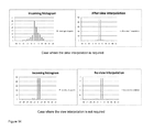
- one potential outcome is an histogram of disparity values in the map. This histogram illustrates the range of disparity values associated with the pair of left view and right view represented by block 1 and 2, and will be used to evaluate the level of depth adjustment represented by block 8 required to achieve 2D/3D compatibility.
- figure 9 block 5 e.g. the size of the screen
- the viewing distance represented by block 6, between the viewer and the display screen.
- figure 12 there is a relationship between the size of the display screen, the viewing distance and the perception of a disparity value on the screen. For a given distance the disparity will appear twice as big on a 50" display screen compared to on a 25" one. On the other hand, the disparity on a 50" display screen will appear bigger if the viewing distance is reduced. The level of disparity is directly related to these viewing conditions.
- HDMI High-Definition Multimedia Interface
- the 2D/3D compatibility mode will be determined thanks to the disparity map analysis, represented by figure 9 block 4, and viewing conditions, represented by block 7.
- the view interpolation level determined to ensure 2D/3D compatibilities, represented by block 8, is the one that can ensure a correct 2D picture without glasses but with still a significant 3D effect with glasses.
- the constraint is then to ensure that a view interpolation, represented by block 9, is applied to reach the level we can accept as a 2D mode without glasses.
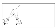
- This level is corresponding to an angle ( ⁇ ) as shown on figure 13 .
- Nb_pix_disp Disp * Nb_pixel_tot / SS
- Nb_pix_disp tg ⁇ * D * Nb_pixel_tot / SS
- tg ⁇ * is a parameter that is fixed by user experience, a satisfying value is for instance 0.0013 which corresponds to 5 pixels at 2m on a 1920 pixels display with 1 m horizontal size.
- the display device presents a new function on the remote control of a Set Top Box (STB) to automatically generate from an incoming stereo content a new stereo content viewable with or without glasses on a 3DTV.
- This new content is generated thanks to a view interpolation system. It uses both left and right incoming views and disparity information extracted from the content. It uses also the viewing condition to determine the view interpolation to be applied.
- the limit of depth obtained at the end is just at the limit accepted to ensure a good 2D experience for people without glasses but with still a 3D effect for people with glasses.
Landscapes
- Engineering & Computer Science (AREA)
- Multimedia (AREA)
- Signal Processing (AREA)
- Testing, Inspecting, Measuring Of Stereoscopic Televisions And Televisions (AREA)
Priority Applications (7)
| Application Number | Priority Date | Filing Date | Title |
|---|---|---|---|
| EP11173451A EP2547109A1 (fr) | 2011-07-11 | 2011-07-11 | Conversion automatique en mode compatible 2D/3D |
| CN201280024390.5A CN103563363A (zh) | 2011-05-19 | 2012-05-16 | 立体视觉图像的自动转换以便允许同时进行图像的立体视觉和平面视觉显示 |
| US14/118,208 US20140085435A1 (en) | 2011-05-19 | 2012-05-16 | Automatic conversion of a stereoscopic image in order to allow a simultaneous stereoscopic and monoscopic display of said image |
| KR1020137030309A KR20140041489A (ko) | 2011-05-19 | 2012-05-16 | 스테레오스코픽 이미지의 동시적인 스테레오스코픽 및 모노스코픽 디스플레이를 가능하게 하기 위한 스테레오스코픽 이미지의 자동 컨버전 |
| PCT/EP2012/059210 WO2012156489A1 (fr) | 2011-05-19 | 2012-05-16 | Conversion automatique d'une image stéréoscopique pour permettre un affichage simultanément stéréoscopique et monoscopique de ladite image |
| EP12721307.2A EP2710804A1 (fr) | 2011-05-19 | 2012-05-16 | Conversion automatique d'une image stéréoscopique pour permettre un affichage simultanément stéréoscopique et monoscopique de ladite image |
| JP2014510813A JP2014515569A (ja) | 2011-05-19 | 2012-05-16 | 両眼視画像の両眼視用および単眼視用の同時表示を可能にするための該両眼視画像の自動変換 |
Applications Claiming Priority (1)
| Application Number | Priority Date | Filing Date | Title |
|---|---|---|---|
| EP11173451A EP2547109A1 (fr) | 2011-07-11 | 2011-07-11 | Conversion automatique en mode compatible 2D/3D |
Publications (1)
| Publication Number | Publication Date |
|---|---|
| EP2547109A1 true EP2547109A1 (fr) | 2013-01-16 |
Family
ID=44487149
Family Applications (1)
| Application Number | Title | Priority Date | Filing Date |
|---|---|---|---|
| EP11173451A Withdrawn EP2547109A1 (fr) | 2011-05-19 | 2011-07-11 | Conversion automatique en mode compatible 2D/3D |
Country Status (1)
| Country | Link |
|---|---|
| EP (1) | EP2547109A1 (fr) |
Cited By (2)
| Publication number | Priority date | Publication date | Assignee | Title |
|---|---|---|---|---|
| WO2014001262A1 (fr) | 2012-06-26 | 2014-01-03 | Thomson Licensing | Procédé pour adapter un contenu en 3d à la vue d'un spectateur qui porte des verres prescrits sur ordonnance |
| TWI556622B (zh) * | 2013-10-14 | 2016-11-01 | 鈺立微電子股份有限公司 | 快速產生照相機的距離對視差關係表的系統及其相關方法 |
Citations (3)
| Publication number | Priority date | Publication date | Assignee | Title |
|---|---|---|---|---|
| WO2002030131A2 (fr) * | 2000-10-04 | 2002-04-11 | University Of New Brunswick | Imagerie combinée en deux/trois dimensions en couleurs |
| WO2009020277A1 (fr) * | 2007-08-06 | 2009-02-12 | Samsung Electronics Co., Ltd. | Procédé et appareil pour reproduire une image stéréoscopique par utilisation d'une commande de profondeur |
| US20090096863A1 (en) * | 2007-10-10 | 2009-04-16 | Samsung Electronics Co., Ltd. | Method and apparatus for reducing fatigue resulting from viewing three-dimensional image display, and method and apparatus for generating data stream of low visual fatigue three-dimensional image |
-
2011
- 2011-07-11 EP EP11173451A patent/EP2547109A1/fr not_active Withdrawn
Patent Citations (3)
| Publication number | Priority date | Publication date | Assignee | Title |
|---|---|---|---|---|
| WO2002030131A2 (fr) * | 2000-10-04 | 2002-04-11 | University Of New Brunswick | Imagerie combinée en deux/trois dimensions en couleurs |
| WO2009020277A1 (fr) * | 2007-08-06 | 2009-02-12 | Samsung Electronics Co., Ltd. | Procédé et appareil pour reproduire une image stéréoscopique par utilisation d'une commande de profondeur |
| US20090096863A1 (en) * | 2007-10-10 | 2009-04-16 | Samsung Electronics Co., Ltd. | Method and apparatus for reducing fatigue resulting from viewing three-dimensional image display, and method and apparatus for generating data stream of low visual fatigue three-dimensional image |
Cited By (2)
| Publication number | Priority date | Publication date | Assignee | Title |
|---|---|---|---|---|
| WO2014001262A1 (fr) | 2012-06-26 | 2014-01-03 | Thomson Licensing | Procédé pour adapter un contenu en 3d à la vue d'un spectateur qui porte des verres prescrits sur ordonnance |
| TWI556622B (zh) * | 2013-10-14 | 2016-11-01 | 鈺立微電子股份有限公司 | 快速產生照相機的距離對視差關係表的系統及其相關方法 |
Similar Documents
| Publication | Publication Date | Title |
|---|---|---|
| US20140085435A1 (en) | Automatic conversion of a stereoscopic image in order to allow a simultaneous stereoscopic and monoscopic display of said image | |
| EP2332340B1 (fr) | Procédé de traitement d'informations de parallaxe comprises dans un signal | |
| US11785197B2 (en) | Viewer-adjusted stereoscopic image display | |
| Smolic et al. | An overview of available and emerging 3D video formats and depth enhanced stereo as efficient generic solution | |
| KR101749893B1 (ko) | 다목적 3―d 화상 포맷 | |
| US9596446B2 (en) | Method of encoding a video data signal for use with a multi-view stereoscopic display device | |
| WO2010048632A1 (fr) | Format d'image stéréoscopique avec informations de profondeurs | |
| WO2010046824A1 (fr) | Procédé et système de traitement d’un signal vidéo tridimensionnel d’entrée | |
| JP2012518317A (ja) | 3d観察者メタデータの転送 | |
| Winkler et al. | Stereo/multiview picture quality: Overview and recent advances | |
| US20130194395A1 (en) | Method, A System, A Viewing Device and a Computer Program for Picture Rendering | |
| KR101686168B1 (ko) | 스트레오스코픽 동영상 파일의 구성 방법 | |
| Tam et al. | Nonuniform smoothing of depth maps before image-based rendering | |
| Tam et al. | Depth image based rendering for multiview stereoscopic displays: Role of information at object boundaries | |
| EP2547109A1 (fr) | Conversion automatique en mode compatible 2D/3D | |
| Pastoor | Human factors of 3DTV: an overview of current research at Heinrich-Hertz-Institut Berlin | |
| CN102447863A (zh) | 一种多视点立体视频字幕处理方法 | |
| EP2721829A1 (fr) | Procédé pour réduire la taille d'une image stéréoscopique | |
| KR101742993B1 (ko) | 디지털 방송 수신기 및 디지털 방송 수신기에서 3d 효과 제공 방법 | |
| KR101733488B1 (ko) | 3차원 영상 표시 방법 및 그에 따른 3차원 영상 표시 장치 | |
| Salman et al. | Overview: 3D Video from capture to Display | |
| US8947507B2 (en) | Method of processing 3D images, and corresponding system including the formulation of missing pixels using windows of details from first and second views | |
| Winkler et al. | Stereoscopic image quality compendium | |
| Jeong et al. | 11.3: Depth‐Image‐Based Rendering (DIBR) Using Disocclusion Area Restoration | |
| McCarthy | Glossary for video & perceptual quality of stereoscopic video |
Legal Events
| Date | Code | Title | Description |
|---|---|---|---|
| PUAI | Public reference made under article 153(3) epc to a published international application that has entered the european phase |
Free format text: ORIGINAL CODE: 0009012 |
|
| AK | Designated contracting states |
Kind code of ref document: A1 Designated state(s): AL AT BE BG CH CY CZ DE DK EE ES FI FR GB GR HR HU IE IS IT LI LT LU LV MC MK MT NL NO PL PT RO RS SE SI SK SM TR |
|
| AX | Request for extension of the european patent |
Extension state: BA ME |
|
| STAA | Information on the status of an ep patent application or granted ep patent |
Free format text: STATUS: THE APPLICATION IS DEEMED TO BE WITHDRAWN |
|
| 18D | Application deemed to be withdrawn |
Effective date: 20130717 |