EP2547276B1 - Ablationskatheter mit isolierter temperaturmessspitze - Google Patents
Ablationskatheter mit isolierter temperaturmessspitze Download PDFInfo
- Publication number
- EP2547276B1 EP2547276B1 EP11709271.8A EP11709271A EP2547276B1 EP 2547276 B1 EP2547276 B1 EP 2547276B1 EP 11709271 A EP11709271 A EP 11709271A EP 2547276 B1 EP2547276 B1 EP 2547276B1
- Authority
- EP
- European Patent Office
- Prior art keywords
- distal tip
- thermocouple
- conductive insert
- tissue
- fluid
- Prior art date
- Legal status (The legal status is an assumption and is not a legal conclusion. Google has not performed a legal analysis and makes no representation as to the accuracy of the status listed.)
- Not-in-force
Links
Images


Classifications
-
- A—HUMAN NECESSITIES
- A61—MEDICAL OR VETERINARY SCIENCE; HYGIENE
- A61B—DIAGNOSIS; SURGERY; IDENTIFICATION
- A61B18/00—Surgical instruments, devices or methods for transferring non-mechanical forms of energy to or from the body
- A61B18/04—Surgical instruments, devices or methods for transferring non-mechanical forms of energy to or from the body by heating
- A61B18/12—Surgical instruments, devices or methods for transferring non-mechanical forms of energy to or from the body by heating by passing a current through the tissue to be heated, e.g. high-frequency current
- A61B18/14—Probes or electrodes therefor
- A61B18/1492—Probes or electrodes therefor having a flexible, catheter-like structure, e.g. for heart ablation
-
- A—HUMAN NECESSITIES
- A61—MEDICAL OR VETERINARY SCIENCE; HYGIENE
- A61B—DIAGNOSIS; SURGERY; IDENTIFICATION
- A61B18/00—Surgical instruments, devices or methods for transferring non-mechanical forms of energy to or from the body
- A61B2018/00005—Cooling or heating of the probe or tissue immediately surrounding the probe
- A61B2018/00011—Cooling or heating of the probe or tissue immediately surrounding the probe with fluids
-
- A—HUMAN NECESSITIES
- A61—MEDICAL OR VETERINARY SCIENCE; HYGIENE
- A61B—DIAGNOSIS; SURGERY; IDENTIFICATION
- A61B18/00—Surgical instruments, devices or methods for transferring non-mechanical forms of energy to or from the body
- A61B2018/00005—Cooling or heating of the probe or tissue immediately surrounding the probe
- A61B2018/00011—Cooling or heating of the probe or tissue immediately surrounding the probe with fluids
- A61B2018/00029—Cooling or heating of the probe or tissue immediately surrounding the probe with fluids open
-
- A—HUMAN NECESSITIES
- A61—MEDICAL OR VETERINARY SCIENCE; HYGIENE
- A61B—DIAGNOSIS; SURGERY; IDENTIFICATION
- A61B18/00—Surgical instruments, devices or methods for transferring non-mechanical forms of energy to or from the body
- A61B2018/00053—Mechanical features of the instrument of device
- A61B2018/00059—Material properties
- A61B2018/00089—Thermal conductivity
- A61B2018/00101—Thermal conductivity low, i.e. thermally insulating
-
- A—HUMAN NECESSITIES
- A61—MEDICAL OR VETERINARY SCIENCE; HYGIENE
- A61B—DIAGNOSIS; SURGERY; IDENTIFICATION
- A61B18/00—Surgical instruments, devices or methods for transferring non-mechanical forms of energy to or from the body
- A61B2018/00571—Surgical instruments, devices or methods for transferring non-mechanical forms of energy to or from the body for achieving a particular surgical effect
- A61B2018/00577—Ablation
-
- A—HUMAN NECESSITIES
- A61—MEDICAL OR VETERINARY SCIENCE; HYGIENE
- A61B—DIAGNOSIS; SURGERY; IDENTIFICATION
- A61B18/00—Surgical instruments, devices or methods for transferring non-mechanical forms of energy to or from the body
- A61B2018/00636—Sensing and controlling the application of energy
- A61B2018/00642—Sensing and controlling the application of energy with feedback, i.e. closed loop control
-
- A—HUMAN NECESSITIES
- A61—MEDICAL OR VETERINARY SCIENCE; HYGIENE
- A61B—DIAGNOSIS; SURGERY; IDENTIFICATION
- A61B18/00—Surgical instruments, devices or methods for transferring non-mechanical forms of energy to or from the body
- A61B2018/00636—Sensing and controlling the application of energy
- A61B2018/00696—Controlled or regulated parameters
- A61B2018/00744—Fluid flow
-
- A—HUMAN NECESSITIES
- A61—MEDICAL OR VETERINARY SCIENCE; HYGIENE
- A61B—DIAGNOSIS; SURGERY; IDENTIFICATION
- A61B18/00—Surgical instruments, devices or methods for transferring non-mechanical forms of energy to or from the body
- A61B2018/00636—Sensing and controlling the application of energy
- A61B2018/00773—Sensed parameters
- A61B2018/00791—Temperature
- A61B2018/00821—Temperature measured by a thermocouple
Definitions
- This application relates generally to medical devices and, more particularly, to systems and methods related to temperature sensing and ablation catheters.
- Aberrant conductive pathways disrupt the normal path of the heart's electrical impulses.
- conduction blocks can cause the electrical impulse to degenerate into several circular wavelets that disrupt the normal activation of the atria or ventricles.
- the aberrant conductive pathways create abnormal, irregular, and sometimes life-threatening heart rhythms called arrhythmias.
- Ablation is one way of treating arrhythmias and restoring normal contraction.
- the sources of the aberrant pathways (called focal arrhythmia substrates) are located or mapped using mapping electrodes. After mapping, the physician may ablate the aberrant tissue.
- RF radio frequency
- Simple RF ablation catheters have a small tip and therefore most of the RF power is dissipated in the tissue.
- the advantage is that the lesion size is somewhat predictable from the RF power and time.
- the tissue can get very hot at the contact point, and thus there can be a problem of coagulum formation.
- Closed irrigation catheters provide additional cooling to the tip, which keeps the tissue at the contact point cooler with less dependence on the local blood velocity. However, the added cooling further masks the amount of RF ablation power dissipated into the tissue.
- the tip temperature is poorly correlated to the tissue temperature.
- Open irrigation catheters cover the tissue near the tip with a cloud of cool liquid to prevent coagulum in the entire region. However, more cooling fluid is used, which further masks the amount of RF power that enters the tissue.
- the tissue temperature profile versus time in the tissue is highly uncertain, which may contribute to under treatment or over treatment. If too much power is used, the tissue temperature may rise above 100° C and result in a steam pop. Steam pops may tear tissue and expel the contents causing risk of embolic damage to the circulation. Additionally, the temperature differs throughout a volume of tissue to be ablated. A steam pop may occur in one part of the tissue volume before the tissue in other parts of the tissue volume reaches a temperature over 50° C and is killed. As a consequence, power may be cautiously applied to avoid steam pop, and the tissue may be under treated resulting in the lesion being smaller than desired. The result of under treatment may be failure to isolate the tissue acutely or chronically, resulting in an inadequate clinical treatment of the arrhythmia.
- US 6,053,912 relates to systems and methods for sensing sub-surface temperatures in body tissue during ablation with actively cooled electrodes.
- the electrode shown therein is adapted to be connected to a source of ablation energy to conduct ablation energy for transmission by the electrode into tissue at the tissue-electrode interface.
- the systems and methods disclosed therein also include an element to cool the electrode.
- the systems and methods shown therein hold a tissue temperature sensing element in a carrier in thermal conductive contact with tissue beneath the tissue electrode interface.
- US 6,053,912 discloses an ablation catheter including a catheter body, a thermocouple component 112, and a sleeve 136 made of thermally insulating material. This sleeve extends from the distal tip through the electrode and into the catheter body.
- the present subject matter provides an ablation catheter system including a catheter body with a distal tip, and a thermocouple component at the distal tip.
- the thermocouple component protrudes from the distal tip.
- the thermocouple component is adapted to sense temperature of bodily fluid and/or tissue.
- the system includes a non-conductive insert configured to physically separate and thermally insulate the thermocouple component from the catheter body.
- the non-conductive insert includes a ceramic material.
- the system includes an open-irrigated ablation catheter system.
- the open-irrigated system includes a catheter body with a distal tip and at least one fluid chamber.
- the system also includes a plurality of irrigation ports within the catheter body, where the plurality of irrigation ports enable fluid to exit from the at least one fluid chamber.
- a thermocouple component at the distal tip is adapted to sense temperature of bodily fluid and/or tissue.
- the system further includes a non-conductive insert configured to physically separate and thermally insulate the thermocouple component from the catheter body and the plurality of irrigation ports.
- RF ablation procedure During an RF ablation procedure, high RF current density near the electrode causes resistive heating in the tissue. This heat is also transferred by convection to surrounding tissue. RF electric current is applied to tissue to locally heat a region of the tissue to a temperature that kills cells (e.g. over 50° C throughout the volume of tissue to be ablated). However, undesired steam pops may occur if the temperature of a portion of the tissue rises to or above 100° C. Therefore, the temperature of the tissue to be ablated should be above 50° C throughout the volume but should not reach 100 ° C anywhere in the volume.
- Irrigated ablation catheters typically have poor temperature sensing capabilities because the cooling flow runs directly over the sensor and creates an artificially low temperature at the sensor.
- the present subject matter minimizes the effects of the cooling flow by thermally insulating the sensor from the fluid.
- the present subject matter relates to a RF ablation catheter that includes an isolated temperature sensing tip.
- the temperature sensing feature is valuable for preventing excessive heating of the ablation electrode and surrounding tissue.
- accurate temperature readings of target tissue at an ablation site are important for applying proper intensity and duration of ablation.
- coagulum formation on the catheter tip can be reduced.
- a reduction in steam pops caused by high temperatures is also possible using the present subject matter.
- a temperature sensing component or thermocouple is positioned in the center of the tip of the catheter, perpendicular to the tip surface, and is adapted for tissue contact in various embodiments.
- the temperature sensing component can be positioned in other orientations besides perpendicularly to the tip surface, in various embodiments.
- the temperature sensing component includes a thermistor, in an embodiment.
- the temperature sensing component can be formed from a metal or metals, or from a ceramic or polymer material, in various embodiments. Other types of temperature sensing components can be used without departing from the scope of this disclosure.
- the temperature sensing component protrudes from the tip surface, in an embodiment.
- the temperature sensing component is recessed from or flush with the tip surface.
- the temperature sensing component is surrounded by a non-conductive insert.
- the non-conductive insert includes a highly porous ceramic material, or ceramic insert, in various embodiments.
- the non-conductive insert is positioned such that it insulates and isolates the temperature sensing component from resistive heating after RF energy is delivered from the tip to perform ablation.
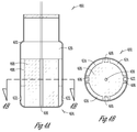
- FIG. 1A-1B illustrate planar and cross-sectional views of an ablation catheter system, according to an embodiment of the present subject matter.
- the ablation catheter system 100 includes a catheter body 102 with a distal tip 104, and a thermocouple component 106 at the distal tip.
- the thermocouple component 106 is adapted to sense temperature of bodily fluid and/or tissue.
- the thermocouple component protrudes from the tip surface, in an embodiment. In other embodiments, the thermocouple component is recessed from or flush with the tip surface.
- the system 100 includes a non-conductive insert 108 configured to physically separate and thermally insulate the thermocouple component 106 from the catheter body 102.
- the non-conductive insert includes a highly porous ceramic material, or ceramic insert, in various embodiments.
- the catheter system includes a center support 110 within the catheter body, in various embodiments.
- the non-conductive insert is further configured to electrically isolate the thermocouple component from the catheter body.
- the catheter body further includes proximal ring electrodes adapted for ECG mapping, in various embodiments, and the non-conductive insert is further adapted to electrically isolate the thermocouple component from the proximal ring electrodes.
- the non-conductive insert includes a porous ceramic material including a large air void percentage per volume, in an embodiment.
- the non-conductive insert includes any insulating material with a low coefficient of thermal transfer.
- the non-conductive insert can be made from any material that would provide thermal and/or electrical isolation of the thermocouple or thermocouples from the tip or body.
- the non-conductive insert includes any ceramic (porous or non-porous), polymeric, adhesive, epoxy, or any other thermal or electrically non-conductive material.
- the non-conductive insert is cylindrically shaped.
- the non-conductive insert can be any shape or configuration to isolate one or more thermocouples and/or one or more cooling fluid flow paths.
- the non-conductive insert can be porous, slotted/scalloped external profile or have discrete internal fluid passageways such as holes or slots.
- thermocouple component is adapted to protrude from a center of the distal tip, in an embodiment. In other embodiments, the thermocouple component is contained within the tip. The thermocouple component is flush with the tip, in further embodiments. In various embodiments, multiple secondary or alternate thermocouples are arranged in a predetermined configuration (geometrically symmetrical, non-symmetrical patterns, radially or axially positioned, linear, randomly located, or other configuration) around or along the tip. Other thermocouple configurations are possible without departing from the scope of this disclosure. In various embodiments, the distal tip has a circular cross section. Other geometries are possible without departing from the scope of this disclosure.
- the thermocouple component is adapted to protrude approximately 1 mm from the distal tip, in one embodiment.
- the thermocouple component is adapted to protrude approximately 0.5 mm to 1.5 mm from the distal tip, in various embodiments.
- the thermocouple component is adapted to protrude greater than approximately 1 mm from the distal tip, in another embodiment.
- the system further includes components common to a bi-directional steerable ablation catheter, such as a center support, steering pull wires, mapping electrode wires and radio frequency wires in various embodiments.
- the thermocouple is positioned perpendicular to a side wall of the distal tip in the depicted embodiment, but other orientations of the thermocouple are possible without departing from the scope of this disclosure.
- FIG. 2A-2B illustrate planar and cross-sectional views of an ablation catheter system with multiple thermocouple components, according to an embodiment of the present subject matter.
- the ablation catheter system 200 includes a catheter body 202 with a distal tip 204, and thermocouple components 206.
- the thermocouple components 206 are adapted to sense temperature of bodily fluid and/or tissue.
- the system 200 includes a non-conductive insert 208 adapted to physically separate and thermally insulate the thermocouple components 206 from the catheter body 202.
- the catheter system includes a center support 210 within the catheter body, in various embodiments.
- the depicted embodiment includes four additional thermocouples 206 positioned 90 degrees apart.
- the catheter system can include n thermocouples positioned 360/n degrees apart in addition to or in place of a centered thermocouple. Other arrangements of the thermocouples are possible without departing from the scope of this disclosure.
- Each of the thermocouples is encased by ceramic insulating material, in various embodiments.
- FIG. 3A-3B illustrate planar and cross-sectional views of an open-irrigated ablation catheter system, according to an embodiment of the present subject matter.
- the open-irrigated system 300 includes a catheter body 302 with a distal tip 304 and at least one fluid chamber 320.
- the system 300 also includes a plurality of irrigation ports 322 within the catheter body, where the plurality of irrigation ports 322 enable fluid to exit from the at least one fluid chamber 320 via a plurality of fluid flow channels 324.
- a thermocouple component 306 at the distal tip is adapted to sense temperature of bodily fluid and/or tissue.
- the system further includes a non-conductive insert 308 adapted to physically separate and thermally insulate the thermocouple component 306 from the catheter body 302, the plurality of irrigation ports 322 and the plurality of fluid flow channels 324.
- the system includes a center support 310, cooling lumens 312, thermocouple wires 314, a proximal insert 316, and one or more electrodes 318.
- the system also includes components common to a bi-directional steerable ablation catheter, such as steering pull wires and radio frequency wires in various embodiments.
- the thermocouple wires attach to a connector at the back of the catheter that is attached to an RF generator having a temperature control algorithm, in various embodiments.
- thermocouple is surrounded by a highly porous ceramic material, and the ceramic material is positioned such that it insulates and isolates the temperature sensing component from the turbulent fluid in the proximal cooling chamber designed to cool the tip, in various embodiments.
- the fluid flow channels are oriented along the length of the cathode body, separated from the temperature sensing component by the ceramic material. Four or more fluid flow channels are used, in various embodiments. Cooling lumens that run the length of the catheter shaft supply the irrigation fluid, in an embodiment.
- a cooling fluid such as a saline
- a saline is delivered through the catheter to the catheter tip, where the fluid exits through irrigation ports to cool the electrode and surrounding tissue.
- Clinical benefits of such a catheter include, but are not limited to, controlling the temperature and reducing coagulum formation on the tip of the catheter, preventing impedance rise of tissue in contact with the catheter tip, and maximizing potential energy transfer to the tissue.
- the non-conductive insert is further adapted to electrically isolate the thermocouple component from the catheter body, and/or to insulate the thermocouple component from the proximal cooling chamber.
- the fluid chamber includes a proximal cooling chamber, in an embodiment.
- the thermocouple is connected via wires to a processor adapted to calculate an amount of fluid needed at the distal tip to cool surrounding tissue based on sensed temperature, in various embodiments.
- the fluid flow channels are oriented such that fluid passing through the catheter and out the distal tip passes along side of an outside diameter of the ceramic material.
- the proximal cooling fluid is isolated from the thermocouple by the non-conductive insert.
- the catheter system combines an open irrigation configuration with accurate temperature sensing capability at the tip of the catheter, which helps prevent excessive heating of the ablation electrode.
- FIG. 4A-4B illustrate planar and cross-sectional views of an open-irrigated ablation catheter system with multiple thermocouple components, according to an embodiment of the present subject matter.
- the open-irrigated system 400 includes a catheter body 402 with a distal tip 404 and at least one fluid chamber 420.
- the system 400 also includes a plurality of irrigation ports 422 within the catheter body, where the plurality of irrigation ports 422 enable fluid to exit from the at least one fluid chamber 420 via a plurality of fluid flow channels 424.
- Thermocouple components 406 at the distal tip are adapted to sense temperature of bodily fluid and/or tissue.
- the system further includes a non-conductive insert (such as a ceramic material) 408 configured to physically separate and thermally insulate the thermocouple components 406 from the catheter body 402, the plurality of irrigation ports 422 and the plurality of fluid flow channels 424.
- a non-conductive insert such as a ceramic material
- the depicted embodiment includes four additional thermocouples 406 positioned 90 degrees apart.
- the catheter system can include n thermocouples positioned 360/n degrees apart in addition to or in place of a centered thermocouple. Other arrangements of the thermocouples are possible without departing from the scope of this disclosure, including those that are not equally spaced around the circumference of the tip.
- modules and other circuitry shown and described herein can be implemented using software, hardware, and/or firmware.
- Various disclosed methods may be implemented as a set of instructions contained on a computer-accessible medium capable of directing a processor to perform the respective method.
Landscapes
- Health & Medical Sciences (AREA)
- Life Sciences & Earth Sciences (AREA)
- Surgery (AREA)
- Engineering & Computer Science (AREA)
- Plasma & Fusion (AREA)
- Medical Informatics (AREA)
- Otolaryngology (AREA)
- Physics & Mathematics (AREA)
- Cardiology (AREA)
- Biomedical Technology (AREA)
- Heart & Thoracic Surgery (AREA)
- Nuclear Medicine, Radiotherapy & Molecular Imaging (AREA)
- Molecular Biology (AREA)
- Animal Behavior & Ethology (AREA)
- General Health & Medical Sciences (AREA)
- Public Health (AREA)
- Veterinary Medicine (AREA)
- Surgical Instruments (AREA)
Claims (14)
- Ablationskathetersystem, welches aufweist:einen Katheterkörper (302; 402) enthaltend eine distale Spitze (304; 404);eine Thermoelementkomponente (306; 406) an der distalen Spitze, wobei die Thermoelementkomponente ausgestaltet ist zum Erfassen der Temperatur von Körperfluid und/oder Gewebe,einen nichtleitenden Einsatz (308; 408), der konfiguriert ist zum physischen Trennen und thermischen Isolieren der Thermoelementkomponente (306; 406) von dem Katheterkörper (302; 402); undwobei der Katheterkörper weiterhin zumindest eine Fluidkammer (320; 420) enthält und das System weiterhin aufweist:mehrere Benetzungsöffnungen (322; 422) innerhalb des Katheterkörpers (302; 402), wobei die mehreren Benetzungsöffnungen (322; 422) ermöglichen, dass Fluid aus der zumindest einen Fluidkammer (320; 420) über mehrere Fluidströmungskanäle (324; 424) austritt, wobei diese Kanäle durch den nichtleitenden Einsatz (308; 408) von der Thermoelementkomponente getrennt sind,wobei der nichtleitende Einsatz (308; 408) konfiguriert ist zum physischen Trennen und thermischen Isolieren der Thermoelementkomponente von den mehreren Benetzungsöffnungen (322; 422); undwobei die Fluidkammer eine proximale Kühlkammer enthält, die proximal von dem nichtleitenden Einsatz (308; 408) angeordnet ist.
- System nach Anspruch 1, bei dem die Thermoelementkomponente (306; 406) innerhalb der distalen Spitze enthalten ist.
- System nach Anspruch 1, bei dem die Thermoelementkomponente (306; 406) bündig mit der distalen Spitze ist.
- System nach Anspruch 1, bei dem die Thermoelementkomponente (306; 406) über die distale Spitze hinaus vorsteht.
- System nach einem der vorhergehenden Ansprüche, bei dem der nichtleitende Einsatz (308; 408) ein keramisches Material enthält.
- System nach einem der vorhergehenden Ansprüche, bei dem der nichtleitende Einsatz (308; 408) weiterhin ausgestaltet ist zum elektrischen Isolieren der Thermoelementkomponente (306; 406) von dem Katheterkörper (302; 402).
- System nach Anspruch 4, bei dem die Thermoelementkomponente (306; 406) ausgestaltet ist, über eine Mitte der distalen Spitze (304; 404) hinaus vorzustehen.
- System nach einem der vorhergehenden Ansprüche, bei dem die distale Spitze (304; 404) einen kreisförmigen Querschnitt hat.
- System nach Anspruch 4, bei dem die Thermoelementkomponente ausgestaltet ist, angenähert 1 mm über die distale Spitze (304; 404) hinaus vorzustehen.
- System nach Anspruch 4, bei dem die Thermoelementkomponente ausgestaltet ist, angenähert 0,5 mm bis 1,5 mm über die distale Spitze hinaus (304; 404) vorzustehen.
- System nach einem der vorhergehenden Ansprüche, bei dem das Thermoelement senkrecht zu einer Seitenwand der distalen Spitze (304; 404) positioniert ist.
- System nach Anspruch 11, weiterhin aufweisend vier Thermoelemente, die um 90 Grad gegeneinander versetzt sind.
- System nach Anspruch 1, bei dem das Thermoelement mit einem Prozessor verbunden ist, der auf der Grundlage der erfassten Temperatur eine Fluidmenge berechnet, die an der distalen Spitze (304; 404) benötigt wird, um das umgebende Gewebe zu kühlen.
- System nach Anspruch 1 oder Anspruch 13, bei dem die Benetzungsöffnungen (322; 422) so orientiert sind, dass durch den Katheter hindurchgehendes und aus der distalen Spitze (304; 404) austretendes Fluid längsseits eines Außendurchmessers des nichtleitenden Einsatzes (308; 408) strömt.
Applications Claiming Priority (2)
| Application Number | Priority Date | Filing Date | Title |
|---|---|---|---|
| US31393610P | 2010-03-15 | 2010-03-15 | |
| PCT/US2011/027591 WO2011115787A1 (en) | 2010-03-15 | 2011-03-08 | Ablation catheter with isolated temperature sensing tip |
Publications (2)
| Publication Number | Publication Date |
|---|---|
| EP2547276A1 EP2547276A1 (de) | 2013-01-23 |
| EP2547276B1 true EP2547276B1 (de) | 2016-08-31 |
Family
ID=44064849
Family Applications (1)
| Application Number | Title | Priority Date | Filing Date |
|---|---|---|---|
| EP11709271.8A Not-in-force EP2547276B1 (de) | 2010-03-15 | 2011-03-08 | Ablationskatheter mit isolierter temperaturmessspitze |
Country Status (5)
| Country | Link |
|---|---|
| US (1) | US20110224667A1 (de) |
| EP (1) | EP2547276B1 (de) |
| JP (1) | JP2013521935A (de) |
| CA (1) | CA2792604A1 (de) |
| WO (1) | WO2011115787A1 (de) |
Families Citing this family (35)
| Publication number | Priority date | Publication date | Assignee | Title |
|---|---|---|---|---|
| US8460285B2 (en) | 2006-12-29 | 2013-06-11 | St. Jude Medical, Atrial Fibrillation Division, Inc. | Ablation catheter electrode having multiple thermal sensors and method of use |
| WO2011008444A1 (en) | 2009-06-30 | 2011-01-20 | Boston Scientific Scimed, Inc. | Map and ablate open irrigated hybrid catheter |
| US20110022041A1 (en) * | 2009-07-24 | 2011-01-27 | Frank Ingle | Systems and methods for titrating rf ablation |
| US9788891B2 (en) * | 2010-12-28 | 2017-10-17 | St. Jude Medical, Atrial Fibrillation Division, Inc. | Ablation electrode assemblies and methods for using same |
| US10201385B2 (en) | 2011-09-01 | 2019-02-12 | Biosense Webster (Israel) Ltd. | Catheter adapted for direct tissue contact |
| US8900228B2 (en) | 2011-09-01 | 2014-12-02 | Biosense Webster (Israel) Ltd. | Catheter adapted for direct tissue contact and pressure sensing |
| CN103315808A (zh) * | 2012-03-23 | 2013-09-25 | 心诺普医疗技术(北京)有限公司 | 一种消融电极及采用该电极的灌注型电极导管 |
| US9393070B2 (en) | 2012-04-24 | 2016-07-19 | Cibiem, Inc. | Endovascular catheters and methods for carotid body ablation |
| US9402677B2 (en) | 2012-06-01 | 2016-08-02 | Cibiem, Inc. | Methods and devices for cryogenic carotid body ablation |
| US9955946B2 (en) | 2014-03-12 | 2018-05-01 | Cibiem, Inc. | Carotid body ablation with a transvenous ultrasound imaging and ablation catheter |
| US9445725B2 (en) * | 2012-12-17 | 2016-09-20 | Biosense Webster (Israel) Ltd. | Irrigated catheter tip with temperature sensor array |
| US20140171936A1 (en) * | 2012-12-17 | 2014-06-19 | Biosense Webster (Israel) Ltd. | Irrigated catheter tip with temperature sensor and optic fiber arrays |
| US9144460B2 (en) | 2012-12-31 | 2015-09-29 | Biosense Webster (Israel) Ltd. | Catheter with direct cooling on nonablating element |
| US10028764B2 (en) | 2013-02-21 | 2018-07-24 | Boston Scientific Scimed, Inc. | Ablation catheter with wireless temperature sensor |
| US10195467B2 (en) | 2013-02-21 | 2019-02-05 | Boston Scientific Scimed, Inc. | Ablation catheter system with wireless radio frequency temperature sensor |
| US9615879B2 (en) | 2013-03-15 | 2017-04-11 | Boston Scientific Scimed, Inc. | Open irrigated ablation catheter with proximal cooling |
| CN105050523B (zh) | 2013-03-15 | 2017-11-10 | 波士顿科学医学有限公司 | 开放式灌注消融导管 |
| EP2859860B1 (de) * | 2013-10-08 | 2017-06-28 | Erbe Elektromedizin GmbH | Multifunktionsinstrument |
| EP3417821B1 (de) * | 2013-10-28 | 2021-06-30 | St. Jude Medical, Cardiology Division, Inc. | Ablationskatheterdesigns mit verbesserten diagnosefähigkeiten |
| EP3220844B1 (de) | 2014-11-19 | 2020-11-11 | EPiX Therapeutics, Inc. | Systeme für hochauflösende gewebekartierung |
| WO2016081650A1 (en) | 2014-11-19 | 2016-05-26 | Advanced Cardiac Therapeutics, Inc. | Ablation devices, systems and methods of using a high-resolution electrode assembly |
| WO2016081611A1 (en) | 2014-11-19 | 2016-05-26 | Advanced Cardiac Therapeutics, Inc. | High-resolution mapping of tissue with pacing |
| US9636164B2 (en) | 2015-03-25 | 2017-05-02 | Advanced Cardiac Therapeutics, Inc. | Contact sensing systems and methods |
| CN107427323B (zh) | 2015-03-31 | 2021-02-02 | 圣犹达医疗用品心脏病学部门有限公司 | 高热敏性消融导管和导管尖端 |
| EP3346925A4 (de) * | 2015-09-11 | 2019-05-22 | Cibiem, Inc. | Glomus-caroticum-ablation mit einer transvenösen ultraschallbildgebung und ablationskatheter |
| SG11201807618QA (en) | 2016-03-15 | 2018-10-30 | Epix Therapeutics Inc | Improved devices, systems and methods for irrigated ablation |
| US11547479B2 (en) * | 2016-08-25 | 2023-01-10 | Gyrus Acmi Inc. | Automatic irrigation-coordinated lithotripsy |
| ES3039648T3 (en) | 2016-10-04 | 2025-10-23 | Avent Inc | Cooled rf probes |
| JP6868097B2 (ja) | 2016-10-04 | 2021-05-12 | セント・ジュード・メディカル,カーディオロジー・ディヴィジョン,インコーポレイテッド | アブレーション・カテーテル・チップのチップ−組織間結合を推定する方法および装置 |
| CN109788982B (zh) * | 2016-10-04 | 2021-11-02 | 圣犹达医疗用品心脏病学部门有限公司 | 消融导管尖端 |
| JP2019528955A (ja) * | 2016-12-19 | 2019-10-17 | ボストン サイエンティフィック サイムド,インコーポレイテッドBoston Scientific Scimed,Inc. | 基端側インサート冷却を用いた開放灌流アブレーションカテーテル |
| EP3614946B1 (de) | 2017-04-27 | 2024-03-20 | EPiX Therapeutics, Inc. | Bestimmung der art des kontaktes zwischen katheterspitze und gewebe |
| WO2018232106A1 (en) | 2017-06-15 | 2018-12-20 | Avent, Inc. | Device to reduce steam pops and increase tissue stability during radiofrequency ablation |
| US12582463B2 (en) * | 2019-04-10 | 2026-03-24 | St. Jude Medical International Holding S.À R.L. | Ablation catheter tip with flexible electronic circuitry |
| US20220395322A1 (en) * | 2021-06-15 | 2022-12-15 | Biosense Webster (Israel) Ltd. | Catheter for high-power focal ablation |
Family Cites Families (13)
| Publication number | Priority date | Publication date | Assignee | Title |
|---|---|---|---|---|
| DE69233091T2 (de) * | 1991-11-08 | 2004-05-06 | Boston Scientific Ltd., St. Michael | Ablationselektrode mit isoliertem temperaturmesselement |
| JPH0779995A (ja) * | 1993-08-20 | 1995-03-28 | Ep Technol Inc | 熱的に絶縁された温度感知素子を有する切除電極 |
| US5853409A (en) * | 1994-06-27 | 1998-12-29 | E.P. Technologies, Inc. | Systems and apparatus for sensing temperature in body tissue |
| US6113591A (en) * | 1994-06-27 | 2000-09-05 | Ep Technologies, Inc. | Systems and methods for sensing sub-surface temperatures in body tissue |
| US5688267A (en) * | 1995-05-01 | 1997-11-18 | Ep Technologies, Inc. | Systems and methods for sensing multiple temperature conditions during tissue ablation |
| US6053912A (en) * | 1995-05-01 | 2000-04-25 | Ep Techonologies, Inc. | Systems and methods for sensing sub-surface temperatures in body tissue during ablation with actively cooled electrodes |
| US6030379A (en) * | 1995-05-01 | 2000-02-29 | Ep Technologies, Inc. | Systems and methods for seeking sub-surface temperature conditions during tissue ablation |
| US6398781B1 (en) * | 1999-03-05 | 2002-06-04 | Gyrus Medical Limited | Electrosurgery system |
| US6611699B2 (en) * | 2001-06-28 | 2003-08-26 | Scimed Life Systems, Inc. | Catheter with an irrigated composite tip electrode |
| US7967816B2 (en) * | 2002-01-25 | 2011-06-28 | Medtronic, Inc. | Fluid-assisted electrosurgical instrument with shapeable electrode |
| US20080091193A1 (en) * | 2005-05-16 | 2008-04-17 | James Kauphusman | Irrigated ablation catheter having magnetic tip for magnetic field control and guidance |
| US7857810B2 (en) * | 2006-05-16 | 2010-12-28 | St. Jude Medical, Atrial Fibrillation Division, Inc. | Ablation electrode assembly and methods for improved control of temperature and minimization of coagulation and tissue damage |
| US8460285B2 (en) * | 2006-12-29 | 2013-06-11 | St. Jude Medical, Atrial Fibrillation Division, Inc. | Ablation catheter electrode having multiple thermal sensors and method of use |
-
2011
- 2011-03-08 EP EP11709271.8A patent/EP2547276B1/de not_active Not-in-force
- 2011-03-08 US US13/043,301 patent/US20110224667A1/en not_active Abandoned
- 2011-03-08 CA CA2792604A patent/CA2792604A1/en not_active Abandoned
- 2011-03-08 WO PCT/US2011/027591 patent/WO2011115787A1/en not_active Ceased
- 2011-03-08 JP JP2013500083A patent/JP2013521935A/ja active Pending
Also Published As
| Publication number | Publication date |
|---|---|
| EP2547276A1 (de) | 2013-01-23 |
| CA2792604A1 (en) | 2011-09-22 |
| US20110224667A1 (en) | 2011-09-15 |
| JP2013521935A (ja) | 2013-06-13 |
| WO2011115787A1 (en) | 2011-09-22 |
Similar Documents
| Publication | Publication Date | Title |
|---|---|---|
| EP2547276B1 (de) | Ablationskatheter mit isolierter temperaturmessspitze | |
| US6692492B2 (en) | Dielectric-coated ablation electrode having a non-coated window with thermal sensors | |
| JP6571217B2 (ja) | 医療装置 | |
| EP3534816B1 (de) | Ballonkatheter für lungenvenenisolierung | |
| US7846158B2 (en) | Apparatus and method for electrode thermosurgery | |
| EP2696790B1 (de) | Vorrichtungen zur steuerung einer ablationstherapie | |
| US9168093B2 (en) | Cooling systems for electrode arrays | |
| JP6388767B2 (ja) | 温度センサーの配列を有する、灌注カテーテル先端部 | |
| EP2563256B1 (de) | Elektrochirurgische vorrichtung | |
| US8834388B2 (en) | Method and apparatus to regulate a tissue temperature | |
| EP2685922B1 (de) | Unabhängiges passivkühlungsdesign für ablationskatheter | |
| US20110160726A1 (en) | Apparatus and methods for fluid cooled electrophysiology procedures | |
| AU2019280061B2 (en) | Irrigated electrodes with enhanced heat conduction | |
| US20030028185A1 (en) | Passively self-cooled electrode design for ablation catheters | |
| CN104379077B (zh) | 用于检测能量递送系统中的通道故障的系统和方法 | |
| AU2019308173A1 (en) | Inferred maximum temperature monitoring for irrigated ablation therapy |
Legal Events
| Date | Code | Title | Description |
|---|---|---|---|
| PUAI | Public reference made under article 153(3) epc to a published international application that has entered the european phase |
Free format text: ORIGINAL CODE: 0009012 |
|
| 17P | Request for examination filed |
Effective date: 20120920 |
|
| AK | Designated contracting states |
Kind code of ref document: A1 Designated state(s): AL AT BE BG CH CY CZ DE DK EE ES FI FR GB GR HR HU IE IS IT LI LT LU LV MC MK MT NL NO PL PT RO RS SE SI SK SM TR |
|
| RIN1 | Information on inventor provided before grant (corrected) |
Inventor name: KOBLISH, JOSEF Inventor name: CHEN, PATRICIA Inventor name: RANKIN, DARRELL, L. Inventor name: KIM, ISAAC Inventor name: TEE, SIEW-HUNG Inventor name: BENCINI, ROBERT, F. Inventor name: FORREST, MARK |
|
| DAX | Request for extension of the european patent (deleted) | ||
| 17Q | First examination report despatched |
Effective date: 20140328 |
|
| GRAP | Despatch of communication of intention to grant a patent |
Free format text: ORIGINAL CODE: EPIDOSNIGR1 |
|
| INTG | Intention to grant announced |
Effective date: 20160330 |
|
| GRAS | Grant fee paid |
Free format text: ORIGINAL CODE: EPIDOSNIGR3 |
|
| GRAA | (expected) grant |
Free format text: ORIGINAL CODE: 0009210 |
|
| AK | Designated contracting states |
Kind code of ref document: B1 Designated state(s): AL AT BE BG CH CY CZ DE DK EE ES FI FR GB GR HR HU IE IS IT LI LT LU LV MC MK MT NL NO PL PT RO RS SE SI SK SM TR |
|
| REG | Reference to a national code |
Ref country code: CH Ref legal event code: EP Ref country code: GB Ref legal event code: FG4D |
|
| REG | Reference to a national code |
Ref country code: IE Ref legal event code: FG4D |
|
| REG | Reference to a national code |
Ref country code: DE Ref legal event code: R096 Ref document number: 602011029803 Country of ref document: DE |
|
| REG | Reference to a national code |
Ref country code: AT Ref legal event code: REF Ref document number: 824261 Country of ref document: AT Kind code of ref document: T Effective date: 20161015 |
|
| REG | Reference to a national code |
Ref country code: LT Ref legal event code: MG4D |
|
| REG | Reference to a national code |
Ref country code: NL Ref legal event code: MP Effective date: 20160831 |
|
| REG | Reference to a national code |
Ref country code: AT Ref legal event code: MK05 Ref document number: 824261 Country of ref document: AT Kind code of ref document: T Effective date: 20160831 |
|
| PG25 | Lapsed in a contracting state [announced via postgrant information from national office to epo] |
Ref country code: FI Free format text: LAPSE BECAUSE OF FAILURE TO SUBMIT A TRANSLATION OF THE DESCRIPTION OR TO PAY THE FEE WITHIN THE PRESCRIBED TIME-LIMIT Effective date: 20160831 Ref country code: HR Free format text: LAPSE BECAUSE OF FAILURE TO SUBMIT A TRANSLATION OF THE DESCRIPTION OR TO PAY THE FEE WITHIN THE PRESCRIBED TIME-LIMIT Effective date: 20160831 Ref country code: LT Free format text: LAPSE BECAUSE OF FAILURE TO SUBMIT A TRANSLATION OF THE DESCRIPTION OR TO PAY THE FEE WITHIN THE PRESCRIBED TIME-LIMIT Effective date: 20160831 Ref country code: NO Free format text: LAPSE BECAUSE OF FAILURE TO SUBMIT A TRANSLATION OF THE DESCRIPTION OR TO PAY THE FEE WITHIN THE PRESCRIBED TIME-LIMIT Effective date: 20161130 Ref country code: RS Free format text: LAPSE BECAUSE OF FAILURE TO SUBMIT A TRANSLATION OF THE DESCRIPTION OR TO PAY THE FEE WITHIN THE PRESCRIBED TIME-LIMIT Effective date: 20160831 |
|
| REG | Reference to a national code |
Ref country code: FR Ref legal event code: PLFP Year of fee payment: 7 |
|
| PG25 | Lapsed in a contracting state [announced via postgrant information from national office to epo] |
Ref country code: LV Free format text: LAPSE BECAUSE OF FAILURE TO SUBMIT A TRANSLATION OF THE DESCRIPTION OR TO PAY THE FEE WITHIN THE PRESCRIBED TIME-LIMIT Effective date: 20160831 Ref country code: NL Free format text: LAPSE BECAUSE OF FAILURE TO SUBMIT A TRANSLATION OF THE DESCRIPTION OR TO PAY THE FEE WITHIN THE PRESCRIBED TIME-LIMIT Effective date: 20160831 Ref country code: GR Free format text: LAPSE BECAUSE OF FAILURE TO SUBMIT A TRANSLATION OF THE DESCRIPTION OR TO PAY THE FEE WITHIN THE PRESCRIBED TIME-LIMIT Effective date: 20161201 Ref country code: SE Free format text: LAPSE BECAUSE OF FAILURE TO SUBMIT A TRANSLATION OF THE DESCRIPTION OR TO PAY THE FEE WITHIN THE PRESCRIBED TIME-LIMIT Effective date: 20160831 Ref country code: ES Free format text: LAPSE BECAUSE OF FAILURE TO SUBMIT A TRANSLATION OF THE DESCRIPTION OR TO PAY THE FEE WITHIN THE PRESCRIBED TIME-LIMIT Effective date: 20160831 Ref country code: AT Free format text: LAPSE BECAUSE OF FAILURE TO SUBMIT A TRANSLATION OF THE DESCRIPTION OR TO PAY THE FEE WITHIN THE PRESCRIBED TIME-LIMIT Effective date: 20160831 |
|
| PG25 | Lapsed in a contracting state [announced via postgrant information from national office to epo] |
Ref country code: RO Free format text: LAPSE BECAUSE OF FAILURE TO SUBMIT A TRANSLATION OF THE DESCRIPTION OR TO PAY THE FEE WITHIN THE PRESCRIBED TIME-LIMIT Effective date: 20160831 Ref country code: EE Free format text: LAPSE BECAUSE OF FAILURE TO SUBMIT A TRANSLATION OF THE DESCRIPTION OR TO PAY THE FEE WITHIN THE PRESCRIBED TIME-LIMIT Effective date: 20160831 |
|
| PG25 | Lapsed in a contracting state [announced via postgrant information from national office to epo] |
Ref country code: SK Free format text: LAPSE BECAUSE OF FAILURE TO SUBMIT A TRANSLATION OF THE DESCRIPTION OR TO PAY THE FEE WITHIN THE PRESCRIBED TIME-LIMIT Effective date: 20160831 Ref country code: BE Free format text: LAPSE BECAUSE OF FAILURE TO SUBMIT A TRANSLATION OF THE DESCRIPTION OR TO PAY THE FEE WITHIN THE PRESCRIBED TIME-LIMIT Effective date: 20160831 Ref country code: CZ Free format text: LAPSE BECAUSE OF FAILURE TO SUBMIT A TRANSLATION OF THE DESCRIPTION OR TO PAY THE FEE WITHIN THE PRESCRIBED TIME-LIMIT Effective date: 20160831 Ref country code: SM Free format text: LAPSE BECAUSE OF FAILURE TO SUBMIT A TRANSLATION OF THE DESCRIPTION OR TO PAY THE FEE WITHIN THE PRESCRIBED TIME-LIMIT Effective date: 20160831 Ref country code: PT Free format text: LAPSE BECAUSE OF FAILURE TO SUBMIT A TRANSLATION OF THE DESCRIPTION OR TO PAY THE FEE WITHIN THE PRESCRIBED TIME-LIMIT Effective date: 20170102 Ref country code: DK Free format text: LAPSE BECAUSE OF FAILURE TO SUBMIT A TRANSLATION OF THE DESCRIPTION OR TO PAY THE FEE WITHIN THE PRESCRIBED TIME-LIMIT Effective date: 20160831 Ref country code: BG Free format text: LAPSE BECAUSE OF FAILURE TO SUBMIT A TRANSLATION OF THE DESCRIPTION OR TO PAY THE FEE WITHIN THE PRESCRIBED TIME-LIMIT Effective date: 20161130 Ref country code: PL Free format text: LAPSE BECAUSE OF FAILURE TO SUBMIT A TRANSLATION OF THE DESCRIPTION OR TO PAY THE FEE WITHIN THE PRESCRIBED TIME-LIMIT Effective date: 20160831 |
|
| REG | Reference to a national code |
Ref country code: DE Ref legal event code: R097 Ref document number: 602011029803 Country of ref document: DE |
|
| PG25 | Lapsed in a contracting state [announced via postgrant information from national office to epo] |
Ref country code: IT Free format text: LAPSE BECAUSE OF FAILURE TO SUBMIT A TRANSLATION OF THE DESCRIPTION OR TO PAY THE FEE WITHIN THE PRESCRIBED TIME-LIMIT Effective date: 20160831 |
|
| PLBE | No opposition filed within time limit |
Free format text: ORIGINAL CODE: 0009261 |
|
| STAA | Information on the status of an ep patent application or granted ep patent |
Free format text: STATUS: NO OPPOSITION FILED WITHIN TIME LIMIT |
|
| 26N | No opposition filed |
Effective date: 20170601 |
|
| PG25 | Lapsed in a contracting state [announced via postgrant information from national office to epo] |
Ref country code: SI Free format text: LAPSE BECAUSE OF FAILURE TO SUBMIT A TRANSLATION OF THE DESCRIPTION OR TO PAY THE FEE WITHIN THE PRESCRIBED TIME-LIMIT Effective date: 20160831 |
|
| REG | Reference to a national code |
Ref country code: CH Ref legal event code: PL |
|
| GBPC | Gb: european patent ceased through non-payment of renewal fee |
Effective date: 20170308 |
|
| PG25 | Lapsed in a contracting state [announced via postgrant information from national office to epo] |
Ref country code: MC Free format text: LAPSE BECAUSE OF FAILURE TO SUBMIT A TRANSLATION OF THE DESCRIPTION OR TO PAY THE FEE WITHIN THE PRESCRIBED TIME-LIMIT Effective date: 20160831 |
|
| REG | Reference to a national code |
Ref country code: IE Ref legal event code: MM4A |
|
| PG25 | Lapsed in a contracting state [announced via postgrant information from national office to epo] |
Ref country code: LU Free format text: LAPSE BECAUSE OF NON-PAYMENT OF DUE FEES Effective date: 20170308 |
|
| REG | Reference to a national code |
Ref country code: FR Ref legal event code: PLFP Year of fee payment: 8 |
|
| PG25 | Lapsed in a contracting state [announced via postgrant information from national office to epo] |
Ref country code: LI Free format text: LAPSE BECAUSE OF NON-PAYMENT OF DUE FEES Effective date: 20170331 Ref country code: GB Free format text: LAPSE BECAUSE OF NON-PAYMENT OF DUE FEES Effective date: 20170308 Ref country code: IE Free format text: LAPSE BECAUSE OF NON-PAYMENT OF DUE FEES Effective date: 20170308 Ref country code: CH Free format text: LAPSE BECAUSE OF NON-PAYMENT OF DUE FEES Effective date: 20170331 |
|
| PG25 | Lapsed in a contracting state [announced via postgrant information from national office to epo] |
Ref country code: MT Free format text: LAPSE BECAUSE OF NON-PAYMENT OF DUE FEES Effective date: 20170308 |
|
| PG25 | Lapsed in a contracting state [announced via postgrant information from national office to epo] |
Ref country code: AL Free format text: LAPSE BECAUSE OF FAILURE TO SUBMIT A TRANSLATION OF THE DESCRIPTION OR TO PAY THE FEE WITHIN THE PRESCRIBED TIME-LIMIT Effective date: 20160831 |
|
| PG25 | Lapsed in a contracting state [announced via postgrant information from national office to epo] |
Ref country code: HU Free format text: LAPSE BECAUSE OF FAILURE TO SUBMIT A TRANSLATION OF THE DESCRIPTION OR TO PAY THE FEE WITHIN THE PRESCRIBED TIME-LIMIT; INVALID AB INITIO Effective date: 20110308 |
|
| PG25 | Lapsed in a contracting state [announced via postgrant information from national office to epo] |
Ref country code: CY Free format text: LAPSE BECAUSE OF NON-PAYMENT OF DUE FEES Effective date: 20160831 |
|
| PG25 | Lapsed in a contracting state [announced via postgrant information from national office to epo] |
Ref country code: MK Free format text: LAPSE BECAUSE OF FAILURE TO SUBMIT A TRANSLATION OF THE DESCRIPTION OR TO PAY THE FEE WITHIN THE PRESCRIBED TIME-LIMIT Effective date: 20160831 |
|
| PG25 | Lapsed in a contracting state [announced via postgrant information from national office to epo] |
Ref country code: TR Free format text: LAPSE BECAUSE OF FAILURE TO SUBMIT A TRANSLATION OF THE DESCRIPTION OR TO PAY THE FEE WITHIN THE PRESCRIBED TIME-LIMIT Effective date: 20160831 |
|
| PG25 | Lapsed in a contracting state [announced via postgrant information from national office to epo] |
Ref country code: IS Free format text: LAPSE BECAUSE OF FAILURE TO SUBMIT A TRANSLATION OF THE DESCRIPTION OR TO PAY THE FEE WITHIN THE PRESCRIBED TIME-LIMIT Effective date: 20161231 |
|
| PGFP | Annual fee paid to national office [announced via postgrant information from national office to epo] |
Ref country code: DE Payment date: 20220203 Year of fee payment: 12 |
|
| PGFP | Annual fee paid to national office [announced via postgrant information from national office to epo] |
Ref country code: FR Payment date: 20220209 Year of fee payment: 12 |
|
| REG | Reference to a national code |
Ref country code: DE Ref legal event code: R119 Ref document number: 602011029803 Country of ref document: DE |
|
| PG25 | Lapsed in a contracting state [announced via postgrant information from national office to epo] |
Ref country code: FR Free format text: LAPSE BECAUSE OF NON-PAYMENT OF DUE FEES Effective date: 20230331 Ref country code: DE Free format text: LAPSE BECAUSE OF NON-PAYMENT OF DUE FEES Effective date: 20231003 |