EP2547470B1 - Anordnung zum ablängen von nagelrohlingen von einem intermittierend zugeführten draht - Google Patents
Anordnung zum ablängen von nagelrohlingen von einem intermittierend zugeführten draht Download PDFInfo
- Publication number
- EP2547470B1 EP2547470B1 EP10784980.4A EP10784980A EP2547470B1 EP 2547470 B1 EP2547470 B1 EP 2547470B1 EP 10784980 A EP10784980 A EP 10784980A EP 2547470 B1 EP2547470 B1 EP 2547470B1
- Authority
- EP
- European Patent Office
- Prior art keywords
- wire
- cutting
- axis
- arrangement according
- cutting knife
- Prior art date
- Legal status (The legal status is an assumption and is not a legal conclusion. Google has not performed a legal analysis and makes no representation as to the accuracy of the status listed.)
- Not-in-force
Links
- 238000005520 cutting process Methods 0.000 title claims description 51
- 239000000463 material Substances 0.000 claims description 11
- 238000006073 displacement reaction Methods 0.000 claims description 10
- 238000000926 separation method Methods 0.000 claims description 3
- 230000015572 biosynthetic process Effects 0.000 claims description 2
- 238000005096 rolling process Methods 0.000 description 4
- 238000004519 manufacturing process Methods 0.000 description 3
- 238000007373 indentation Methods 0.000 description 2
- 238000000034 method Methods 0.000 description 2
- 238000000465 moulding Methods 0.000 description 2
- 241000587161 Gomphocarpus Species 0.000 description 1
- 238000005452 bending Methods 0.000 description 1
- 210000000080 chela (arthropods) Anatomy 0.000 description 1
- 238000010276 construction Methods 0.000 description 1
- 238000005336 cracking Methods 0.000 description 1
- 230000007246 mechanism Effects 0.000 description 1
- 230000002093 peripheral effect Effects 0.000 description 1
- 239000007787 solid Substances 0.000 description 1
- 230000001360 synchronised effect Effects 0.000 description 1
Images


Classifications
-
- B—PERFORMING OPERATIONS; TRANSPORTING
- B21—MECHANICAL METAL-WORKING WITHOUT ESSENTIALLY REMOVING MATERIAL; PUNCHING METAL
- B21F—WORKING OR PROCESSING OF METAL WIRE
- B21F11/00—Cutting wire
-
- B—PERFORMING OPERATIONS; TRANSPORTING
- B21—MECHANICAL METAL-WORKING WITHOUT ESSENTIALLY REMOVING MATERIAL; PUNCHING METAL
- B21G—MAKING NEEDLES, PINS OR NAILS OF METAL
- B21G3/00—Making pins, nails, or the like
- B21G3/16—Pointing; with or without cutting
-
- B—PERFORMING OPERATIONS; TRANSPORTING
- B21—MECHANICAL METAL-WORKING WITHOUT ESSENTIALLY REMOVING MATERIAL; PUNCHING METAL
- B21G—MAKING NEEDLES, PINS OR NAILS OF METAL
- B21G3/00—Making pins, nails, or the like
- B21G3/18—Making pins, nails, or the like by operations not restricted to one of the groups B21G3/12 - B21G3/16
- B21G3/20—Making pins, nails, or the like by operations not restricted to one of the groups B21G3/12 - B21G3/16 from wire of indefinite length
-
- B—PERFORMING OPERATIONS; TRANSPORTING
- B23—MACHINE TOOLS; METAL-WORKING NOT OTHERWISE PROVIDED FOR
- B23D—PLANING; SLOTTING; SHEARING; BROACHING; SAWING; FILING; SCRAPING; LIKE OPERATIONS FOR WORKING METAL BY REMOVING MATERIAL, NOT OTHERWISE PROVIDED FOR
- B23D25/00—Machines or arrangements for shearing stock while the latter is travelling otherwise than in the direction of the cut
- B23D25/02—Flying shearing machines
- B23D25/06—Flying shearing machines having a cutting device mounted on an oscillating lever
Definitions
- the invention relates to an arrangement for cutting nail blanks from an intermittently fed wire with simultaneous formation of a nail tip by means of a cutting device comprising two mutually opposite with respect to the wire longitudinal axis, mutually opposite cutting tools each with a carrier held by a cutting blade, which together with the Carrier is displaceable between an upper remote from the wire, retracted end position and a lower end extended to the wire perpendicular to the wire longitudinal axis, wherein the wire is extended due to a displacement of wire material by the cutting blade in each cut in the direction away from the free end of the wire around a longitudinal portion.
- the WO 03/101643 A1 describe a rotating and continuously operating cutting system with clamping elements, which are mounted on the circumference of rotating cutting wheels in the direction of rotation in front of and / or behind the also there fixed blades.
- this kind of Section shows, however, that the accuracy of the length of each cut pin varies much more than intermittently operating machines.
- a rotating, continuously operating cutting system is in the EP 0 924 007 B1 described in which are driven by a superposition gear, the speed of the knife with a synchronous to the feed speed of the wire peripheral speed. In this case, however, no cutting takes place during a cutting process and, moreover, the accuracy of the length of the cut-off pin is again significantly more variable than in intermittently operating machines.
- a similarly working rotating, continuously working editing system shows the US 4,310,032 A in which a wire feed is followed by a roller carrying two blades offset by 180 ° with respect to one another, with no peak generation taking place during the cut.
- a material displacement occurs in both wire directions and the accuracy of the length of the cut pins varies more than in intermittently driven machines.
- the DE 24 22 815 C3 describes a crank drive for the radial and axial driving of two opposing knives, wherein also here the cut takes place in a continuously running workpiece.
- This known cutting arrangement involves a very high overall mechanical complexity, the entire device is very large.
- the present invention seeks to provide a cutting arrangement of the type mentioned above such that with intermittent material supply a Compensation of the wire length is ensured in the direction of the fixed end of the workpiece to be separated.
- each cutting blade is moved during the cutting process in its radial displacement movement even in the longitudinal direction of the wire to its free end relative to the wire by a predetermined distance, which is greater than the longitudinal section.
- the inventive measures it is achieved that during the cutting process in which the wire material is displaced in both longitudinal directions of the wire due to the superimposed movement in the wire longitudinal direction, the elongation of the wire by the displaced wire material in the direction of indentation compensated and thus prevents the existing in the prior art risk of the occurrence of buckling, bending or unwanted length tolerances in the direction of the straightening apparatus or to the coil out occurs.
- the measures according to the invention can be implemented without much effort and are considerably less complicated than when, for example, in an intermittently operating machine. B. wanted to use elaborate mechanisms to compensate for the elongation for the displacement of feeder tongs.
- a particularly preferred embodiment of the invention is that each cutting blade is attached to the end of a connecting rod, which in turn is driven via a crank pin provided eccentrically on a crankshaft.
- the cutting movement of the knife runs on an elliptical path, in the passage of which the knives perform a pivoting movement during the cutting movement.
- the web is designed so that the horizontal component of the ellipse from the point of impact on the wire to the complete production of the tip (separation) has the required greater length than the elongation of the material due to displacement in the direction of the solid pliers towards.
- the knife also a rolling motion, resulting in a particularly good quality of the tip due to a high-quality cut and only a very small cracking occurs.
- the unavoidable in the production of such nail blanks length tolerances of the pin produced arise in the invention, however, in the form of only very small length deviations.
- a further preferred embodiment of the invention consists in the use of a connecting rod in that each connecting rod is displaceably guided in a guide body, which in turn is pivotable about a pivot axis arranged parallel to the central axis of the crankshaft.
- a connecting rod in that each connecting rod is displaceably guided in a guide body, which in turn is pivotable about a pivot axis arranged parallel to the central axis of the crankshaft.
- each connecting rod is pivotally mounted about a pivot axis on a guide lever, which in turn is pivotable about an axis parallel to the central axis of the crank axle.
- the use of a linear guide in the connecting rod is avoided.
- a further advantageous embodiment of the invention is also the fact that the predetermined distance, along which each cutting blade moves relative to the wire in the longitudinal direction during the cutting process, is adjustable. This can be taken into account when cutting different thickness nail blanks, whereby the arrangement of the invention is very flexible.
- this can be carried out in the arrangement according to the invention in the embodiment with a connecting rod and a pivotable guide body or with a pivotable guide lever in that the distance of each pivot axis or the axis about which the guide lever pivots, is adjustable by the longitudinal axis of the wire ,
- the ellipse shape of the trajectory of the knife can be adjusted in shape as well as in size.
- Arrangement shown for cutting nail blanks comprises a feed unit 1 and a cutting unit 2 for cutting and simultaneous forming and sharpening of the workpiece 3 (in plan view).
- the infeed unit 1 is shown only schematically as a pincers feeder having a fixed feed tong 4 and a movable feed gun 5, which are equipped with gripping jaws or other means (not shown) for holding the workpiece 3 (wire).
- the movable retraction forceps 4 grips the wire 3 in a left end position and pushes it to the right when moving in the direction B of the retraction forceps 5 parallel to the wire longitudinal axis A.
- the fixed feed tong 4 grips the wire 3, after which the movable feed tong 5 can be opened and its left starting position can be moved back.
- any other intermittently actuated intake systems eg. As a roller feeder, can be used.
- the system works intermittently, the wire 3 is disconnected if it makes no axial movement (feed movement).
- the cutting unit 2 comprises two identically constructed, mirror-inverted to the wire longitudinal axis A arranged cutting modules. 6
- Each cutting module 6 has a crankshaft 7, which at an in Fig. 1 not shown drive in the direction of arrow C is rotated about an axis of rotation 8 (the crankshaft of the second module rotates correspondingly in opposite directions).
- the crank pin 9 has a central axis 10, which is offset by a certain eccentricity e to the axis of rotation 8 of the crankshaft 7. This distance e corresponds to half the distance f between the knife 8 and the wire longitudinal axis A.
- a connecting rod 12 On the crank pin 9 is rotatably seated a connecting rod 12, the free end 13 in a guide body 14, and linearly slidably mounted in this is stored.
- the guide body 14 is freely pivotable about a pivot axis 20.
- a knife 11 At the lower end side of the connecting rod end 13, a knife 11 is used for separating and molding of the nail tip.
- the blade 11 fastened to the free end 13 of the same passes through an elliptical trajectory curve during a rotation of the crankshaft 7 (by 360 °). At the same time a rolling movement of the blade 11 relative to the wire 3 is achieved during the cut.
- FIG. 2 To show a cutting process shows Fig. 2 four different settings of the cutting modules 6, wherein the crankshafts 7 are each further rotated by 90 ° (clockwise).
- Fig. 3 is a basic arrangement accordingly Fig. 1 shown here, in contrast to each connecting rod 12 but no longer displaceable in a guide body 14, but on a about a central axis 8 of the crankshaft 7 parallel axis 23 pivotally mounted guide lever 22 is articulated via a pivot axis 21, which in turn also to the central axis the crankshaft 7 is parallel.
- the pivot axis 21 is attached to the connecting rod 12 facing the end of the guide lever 22 and the axis 23 is arranged at its opposite end. While in the presentation of the Fig. 3 the knives 11 are shown in their fully disassembled condition, they are in Fig. 4 shown in a contracted state.
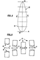
- Fig. 5 shows a typical elliptical trajectory 15 of a knife 11, wherein the tangent at in the FIG. 3 lower end of the ellipse of the wire central axis A corresponds.
- the knife is moved downwardly from the top dead center 16 along the ellipse 15 until it impacts the outer circumference of the wire 3 at point 17. During further movement, the knife 11 penetrates deeper into the wire 3, until it reaches the bottom dead center 18, which lies in the wire central axis A , where the knife with the simultaneous production of a tip 19, the wire 3 separated. In the subsequent movement, the knife 11 is again transported to its top dead center 16.
- Fig. 6 are, after all, in only a very principled representation, for the four already in Fig. 2 shown positions of the two cutting modules 6, the corresponding positions of the blades 11 indicated to represent the pivoting movement, which performs each blade 11 relative to the wire 3 when passing through the different stages.
- each blade 11 moves in a kind of rolling movement relative to the wire 3, whereby a particularly good cut quality at the tip 19 is achieved.
- the cutting modules 6 can be designed so that the shape of the elliptical trajectory 15 is variable, z. B. the ellipse can be made thicker or slimmer, z. B. by changing the distance of each pivot axis 20 of the wire longitudinal axis A.
Landscapes
- Engineering & Computer Science (AREA)
- Mechanical Engineering (AREA)
- Wire Processing (AREA)
- Treatment Of Fiber Materials (AREA)
- Shearing Machines (AREA)
Description
- Die Erfindung bezieht sich auf eine Anordnung zum Ablängen von Nagelrohlingen von einem intermittierend zugeführten Draht unter gleichzeitiger Ausbildung einer Nagelspitze mittels einer Schneideinrichtung, die zwei einander bezüglich der Drahtlängsachse gegenüberliegende, zueinander gegenläufige Schneidwerkzeuge mit je einem von einem Träger gehaltenen Schneidmesser umfaßt, das zusammen mit dem Träger zwischen einer oberen vom Draht entfernten, eingezogenen Endstellung und einer unteren zum Draht hin ausgefahrenen Endstellung senkrecht zur Drahtlängsachse verschiebbar ist, wobei der Draht infolge einer Verdrängung von Drahtmaterial durch die Schneidmesser bei jedem Schnitt in Richtung vom freien Drahtende weg um einen Längsabschnitt verlängert wird.
- Um an einem Draht eine Nagelspitze anzubringen, muß man mit zwei Messern diese Spitze formkneifen, was so an Nagelmaschinen seit jeher ausgeführt wird. Die Bewegung der Messer ist linear und gerade aufeinanderzu. Dabei wird schließlich der Draht geteilt und durch das Verdrängen des Materiales weicht der Draht in beide Drahtrichtungen aus.
- Dieses Ausweichen des Drahtes in seine beiden Richtungen ist in Richtung seines freien Endes problemlos, in der Gegenrichtung, also in Richtung auf den Richtapparat bzw. Coil hin, führt dies aber zum Ausknicken des Drahtes, da hier der Draht nicht ausweichen kann. Üblicherweise löst man dies dadurch, daß ein in einer Nagelmaschine integrierter Festhalter so gesteuert wird, daß dabei die Längenänderung kompensiert wird. Diesen Festhalter axial verschiebbar aufzubauen, ist jedoch sehr aufwendig und unter den Betriebsbedingungen sehr anfällig.
- Aus der
US 5 207 084 A auf welcher der Oberbegriff des Anspruchs 1 basiert, sind ein Verfahren und ein Messer zum Anformen spezieller Drahtenden (wie Spitzen, Keile) bekannt. Allerdings findet auch dort beim Schnitt eine Materialverdrängung in beide Drahtrichtungen statt. - Die
WO 03/101643 A1 - Aus der
EP 1 293 274 B1 ist eine Vorrichtung zum Ablängen von Draht bekannt, die mit einem Stechmeißel zum Durchtrennen des Drahtes arbeitet. Der Stechmeißel ist radial gegen den Draht verfahrbar und um eine Schwenkachse entgegen einer Federkraft auslenkbar. Dabei findet aber weder eine Spitzenerzeugung statt, noch liegt eine einigermaßen definierte Bewegungsbahn vor. - Ein rotierendes, kontinuierlich arbeitendes Schneidsystem ist in der
EP 0 924 007 B1 beschrieben, bei dem durch ein Überlagerungsgetriebe die Geschwindigkeit der Messer mit einer zur Zuführgeschwindigkeit des Drahtes synchronen Umfangsgeschwindigkeit angetrieben werden. Hierbei findet bei einem Schnittvorgang allerdings keine Spitzenherstellung statt und im übrigen ist die Genauigkeit der Länge des abgeschnittenen Stiftes wieder deutlich stärker variierend als bei intermittierend arbeitenden Maschinen. - Ein ähnlich arbeitendes rotierendes, kontinuierlich arbeitendes Schnittsystem zeigt die
US 4 310 032 A , bei dem einem Drahteinzug eine zwei um 180° zueinander versetzte Messer tragende Walze nachgeschaltet ist, wobei beim Schnitt jedoch keine Spitzenerzeugung stattfindet. Bei diesem bekannten Schnittsystem tritt eine Materialverdrängung in beide Drahtrichtungen auf und die Genauigkeit der Länge der abgeschnittenen Stifte variiert stärker als bei intermittierend angetriebenen Maschinen. - Die
DE 24 22 815 C3 beschreibt einen Kurbeltrieb zum radialen und axialen Antreiben zweier einander gegenüberliegender Messer, wobei auch hier der Schnitt bei einem kontinuierlich laufenden Werkstück erfolgt. Diese bekannte Schneidanordnung beinhaltet insgesamt einen sehr hohen mechanischen Aufwand, wobei die gesamte Einrichtung sehr groß baut. - Aus der
US 5 181 886 A ist eine Anordnung der einleitend genannten Art bekannt, bei welcher der Kopf des Nagels angestaucht, sodann der Draht transportiert und anschließend beim Abtrennen die Spitze hergestellt wird. Bei dieser Maschine tritt die bekannte Materialverdrängung in beide Richtungen beim Schnitt auf, wobei der nächste Nagelkopf vorgeformt wird. Die Bewegung der Messer ist rein radial. Ähnliche Nagelmaschinen sind auch in derJP 09151918 A EP 0 554 665 A beschrieben. - Ausgehend hiervon liegt der Erfindung die Aufgabe zugrunde, eine Schneidanordnung der vorstehend genannten Art derart auszubilden, daß bei intermittierender Werkstoffzufuhr eine Kompensation der Drahtlänge in Richtung des festen Endes des abzutrennenden Werkstücks sichergestellt wird.
- Erfindungsgemäß wird dies dadurch erreicht, daß jedes Schneidmesser während des Schnittvorganges bei seiner radialen Verschiebebewegung auch noch in Längsrichtung des Drahtes zu dessen freiem Ende hin relativ zum Draht um eine vorgegebne Strecke bewegt wird, die größer als der Längsabschnitt ist.
- Durch die erfindungsgemäßen Maßnahmen wird erreicht, daß während des Schneidvorganges, bei dem das Drahtmaterial in beide Längsrichtungen des Drahtes verdrängt wird, infolge der überlagerten Bewegung in Drahtlängsrichtung die auftretende Längung des Drahtes durch das verdrängte Drahtmaterial in Richtung Einzug kompensiert und damit verhindert wird, daß die beim Stand der Technik bestehende Gefahr des Auftretens einer Knickung, Verbiegung oder unerwünschter Längentoleranzen in Richtung auf den Richtapparat bzw. zum Coil hin auftritt. Dabei sind die erfindungsgemäßen Maßnahmen ohne großen Aufwand realisierbar und deutlich weniger kompliziert als wenn man bei einer intermittierend arbeitenden Maschine z. B. für die Verschiebung von Einzugszangen aufwendige Mechanismen zur Kompensation der Längung einsetzten wollte.
- Eine besonders bevorzugte Ausgestaltung der Erfindung besteht darin, daß jedes Schneidmesser am Ende eines Pleuels angebracht ist, der seinerseits über einen exzentrisch an einer Kurbelwelle vorgesehenen Kurbelzapfen angetrieben wird. Bei dieser Ausgestaltung verläuft die Schnittbewegung der Messer auf einer ellipsenförmigen Bahn, bei deren Durchlauf die Messer bei der Schnittbewegung auch eine Schwenkbewegung ausführen. Dabei ist die Bahn so ausgelegt, daß die horizontale Komponente der Ellipse vom Auftreffpunkt auf den Draht bis zur vollständigen Herstellung der Spitze (Trennung) die geforderte größere Länge als die Längung des Materials infolge Verdrängung in Richtung auf die feste Einzugszange hin aufweist. Gleichzeitig führen bei dieser Ausgestaltung die Messer auch noch eine Abrollbewegung aus, was infolge eines hochwertigen Schnittes zu einer besonders guten Qualität der Spitze führt und dabei nur eine sehr geringe Rißzone auftritt. Die bei der Herstellung solcher Nagelrohlinge unvermeidbaren Längentoleranzen des erzeugten Stiftes ergeben sich bei der Erfindung jedoch in Form nur besonders kleiner Längenabweichungen.
- Eine weiter bevorzugte Ausführungsform der Erfindung besteht bei der Verwendung eines Pleuels darin, daß jeder Pleuel in einem Führungskörper verschieblich geführt ist, der seinerseits um eine zur Mittelachse der Kurbelwelle parallel angeordnete Schwenkachse verschwenkbar ist. Hierbei wird die elliptische Bahnkurve durch eine Kurbelwelle und eine schwenkbare Linearführung (in Form des Führungskörpers) realisiert, was einen vergleichsweisen geringen Aufwand darstellt und praktisch zu besonders guten Nagelspitzen, ohne Spaltspitze führt.
- Eine andere vorzugsweise Ausbildung der Erfindung bei der Verwendung eines Pleuels besteht auch darin, daß jeder Pleuel um eine Schwenkachse verschwenkbar an einem Führungshebel befestigt ist, der seinerseits um eine zur Mittelachse der Kurbelachse parallele Achse verschwenkbar ist. Bei dieser Ausgestaltung der Erfindung wird der Einsatz einer Linearführung beim Pleuel vermieden.
- Eine weitere vorteilhafte Ausgestaltung der Erfindung besteht auch darin, daß die vorgegebene Strecke, längs derer sich jedes Schneidmesser beim Schnittvorgang relativ zum Draht in dessen Längsrichtung bewegt, einstellbar ist. Damit kann beim Schnitt unterschiedlich dicken Nagelrohlingen Rechnung getragen werden, wodurch die erfindungsgemäße Anordnung sehr flexibel einsetzbar ist.
- Besonders bevorzugt kann dies bei der erfindungsgemäßen Anordnung in der Ausgestaltung mit einem Pleuel und einem verschwenkbaren Führungskörper oder mit einem verschwenkbaren Führungshebel dadurch vorgenommen werden, daß der Abstand jeder Schwenkachse bzw. der Achse, um die der Führungshebel schwenkt, von der Längsachse des Drahtes verstellbar ist. Bei diesem Aufbau der Schnitteinheit kann die Ellipsenform der Bewegungsbahn der Messer nach Form, wie auch nach Größe eingestellt werden.
- Die Erfindung wird nachfolgend anhand der Zeichnung im Prinzip beispielshalber noch näher erläutert. Es zeigen:
- Fig. 1
- eine prinzipielle Darstellung einer Ansicht einer erfindungsgemäßen Anordnung;
- Fig. 2
- eine prinzipielle Darstellung des Schnittablaufes im Rahmen unterschiedlicher, nacheinander liegender Bewegungsstadien der Schneidmesser;
- Fig. 3
- eine prinzipielle Darstellung einer Ansicht entsprechend
Fig. 1 , wobei der Pleuel an einem Führungshebel angelenkt ist, bei auseinandergefahrenen Messern; - Fig. 4
- die Ansicht aus
Fig. 3 , aber mit voll zusammengefahrenen Messern; - Fig. 5
- eine prinzipielle Darstellung der elliptischen Bahnkurve eines Schneidmessers, sowie
- Fig. 6
- eine prinzipielle Darstellung der Abrollbewegung der Schneidmesser bei einer erfindungsgemäßen Anordnung.
- In der nachfolgenden Figurenbeschreibung sind auch bei unterschiedlichen Ausführungsformen einander entsprechende Teile stets mit gleichen Bezugszeichen bezeichnet.
- Die in
Fig. 1 gezeigte Anordnung zum Ablängen von Nagelrohlingen umfaßt eine Einzugseinheit 1 sowie eine Schnitteinheit 2 zum Abtrennen und gleichzeitigem Umformen sowie Anspitzen des Werkstücks 3 (in Draufsicht). - In der Darstellung der
Fig. 1 ist die Einzugseinheit 1 nur schematisch als ein Zangeneinzug dargestellt, der eine feste Einzugszange 4 und eine bewegliche Einzugszange 5 aufweist, die mit Greifbacken oder sonstigen Mitteln (nicht dargestellt) zum Festhalten des Werkstücks 3 (Draht) ausgerüstet sind. - Bei Betrieb ergreift die bewegliche Einzugszange 4 den Draht 3 in einer linken Endlage und schiebt diesen bei der Bewegung in Richtung B der Einzugszange 5 parallel zu der Drahtlängsachse A nach rechts. In der rechten Endlage ergreift die feste Einzugszange 4 den Draht 3, wonach die bewegliche Einzugszange 5 geöffnet und ihre linke Ausgangsstellung zurückbewegt werden kann.
- Es versteht sich von selbst, daß anstelle dieses sogenannten Zangeneinzugs auch beliebige andere intermittierend betätigbare Einzugssysteme, z. B. ein Walzeneinzug, zum Einsatz kommen können. Die Anlage arbeitet intermittierend, wobei der Draht 3 getrennt wird, wenn er keine Axialbewegung (Vorschubbewegung) macht.
- Die Schnitteinheit 2 umfaßt zwei identisch aufgebaute, spiegelbildlich zur Drahtlängsachse A angeordnete Schnittmodule 6.
- Jeder Schnittmodul 6 weist eine Kurbelwelle 7 auf, die bei einem in
Fig. 1 nicht dargestellten Antrieb in Pfeilrichtung C um eine Drehachse 8 gedreht wird (die Kurbelwelle des zweiten Moduls dreht sich entsprechend gegensinnig). - Der Kurbelzapfen 9 hat eine Mittelachse 10, die um eine bestimmte Exzentrizität e zur Drehachse 8 der Kurbelwelle 7 versetzt ist. Dieser Abstand e entspricht dem halben Abstand f zwischen Messer 8 und der Drahtlängsachse A .
- Auf dem Kurbelzapfen 9 sitzt verdrehbar ein Pleuel 12, dessen freies Ende 13 in einem Führungskörper 14, und zwar linear in diesem verschiebbar, gelagert ist. Der Führungskörper 14 ist um eine Schwenkachse 20 frei verschwenkbar. An der unteren Stirnseite des Pleuelendes 13 ist ein Messer 11 zum Trennen und Anformen der Nagelspitze eingesetzt.
- Durch die Zwangsführung des Pleuels 12 durchlauft das am freien Ende 13 desselben befestigten Messer 11 bei einer Drehung der Kurbelwelle 7 (um 360°) eine elliptische Bahnkurve. Gleichzeitig wird dabei auch eine Abrollbewegung des Messers 11 gegenüber dem Draht 3 beim Schnitt erreicht.
- Zur Darstellung eines Schnittvorgangs zeigt
Fig. 2 vier verschiedene Einstellungen der Schnittmodule 6, wobei die Kurbelwellen 7 jeweils um 90° (im Uhrzeigersinn) weitergedreht sind. - In der Darstellung ganz links in
Fig. 2 befinden sich die Messer 11 in ihrem vom Draht 3 abgewandten Totpunkt 16. Die zweite Darstellung vonFig. 2 zeigt die Messer 11 auf ihrem Weg zum unteren Totpunkt 18, den sie schließlich in der dritten Stellung erreicht haben. Damit ist der Draht 3 getrennt und die Spitze 19 des Werkstücks hergestellt, ehe sich die Messer wieder zu ihrem oberen Totpunkt 16 bewegen. - In
Fig. 3 ist eine prinzipielle Anordnung entsprechendFig. 1 gezeigt, wobei hier im Unterschied dazu jeder Pleuel 12 jedoch nicht mehr in einem Führungskörper 14 verschieblich, sondern an einem um eine zur Mittelachse 8 der Kurbelwelle 7 parallele Achse 23 verschwenkbar angebrachten Führungshebel 22 über eine Schwenkachse 21 angelenkt ist, die ihrerseits ebenfalls zur Mittelachse 8 der Kurbelwelle 7 parallel liegt. Dabei ist bei der dargestellten Ausführungsform die Schwenkachse 21 an dem dem Pleuel 12 zugewandten Ende des Führungshebels 22 angebracht und die Achse 23 an dessen entgegengesetztem Ende angeordnet. Während bei der Darstellung derFig. 3 die Messer 11 in ihrem voll auseinandergefahrenem Zustand gezeigt sind, sind sie inFig. 4 in einem zusammengefahrenen Zustand dargestellt. -
Fig. 5 zeigt eine typische elliptische Bewegungsbahn 15 eines Messers 11, wobei die Tangente am in derFigur 3 unteren Ende der Ellipse der Drahtmittelachse A entspricht. - Das Messer wird von dem oberen Totpunkt 16 nach unten längs der Ellipse 15 bewegt, bis es am Punkt 17 auf den Außenumfang des Drahtes 3 auftrifft. Bei der weiteren Bewegung dringt das Messer 11 tiefer in den Draht 3, bis es zum unteren Totpunkt 18 gelangt, der in der Drahtmittelachse A liegt, wo das Messer bei gleichzeitiger Herstellung einer Spitze 19 den Draht 3 abtrennt. Bei der weiteren, folgenden Bewegung wird das Messer 11 wieder in seine obere Totpunktlage 16 befördert.
- Zwischen den Punkten 17 und 18 wird das Drahtmaterial von der speziellen Schneidegeometrie der Messer 11 verdrängt.
- In
Fig. 6 sind schließlich, in einer nur ganz prinzipiellen Darstellung, für die vier bereits inFig. 2 gezeigten Positionen der beiden Schnittmodule 6 die entsprechenden Stellungen der Messer 11 angegeben, um die Schwenkbewegung darzustellen, die jedes Messer 11 relativ zum Draht 3 bei Durchgang durch die unterschiedlichen Stadien ausführt. - Wie aus
Fig. 6 erkennbar ist, bewegt sich jedes Messer 11 in einer Art abrollender Bewegung gegenüber dem Draht 3, wodurch eine besonders gute Schnittqualität an der Spitze 19 erreicht wird. - Die Schnittmodule 6 können so ausgelegt werden, daß die Form der ellipsenförmigen Bewegungsbahn 15 veränderbar ist, z. B. die Ellipse dicker oder schlanker ausgebildet werden kann, z. B. durch Veränderung des Abstandes jeder Schwenkachse 20 von der Drahtlängsachse A.
Claims (6)
- Anordnung zum Ablängen von Nagelrohlingen von einem intermittierend zugeführten Draht (3) unter gleichzeitiger Ausbildung einer Nagelspitze (19) mittels einer Schneideinrichtung (2), die zwei einander bezüglich der Drahtlängsachse (A) gegenüberliegende, zueinander gegenläufige Schneidwerkzeuge (6) mit je einem von einem Träger gehaltenen Schneidmesser (11) umfaßt, das zusammen mit dem Träger zwischen einer oberen, vom Draht (3) entfernten, eingezogenen Endstellung (16) und einer unteren, zum Draht (3) hin ausgefahrenen Endstellung (18) senkrecht zur Drahtlängsachse (A) verschiebbar ist, wobei der Draht (3) infolge einer Verdrängung von Drahtmaterial durch die Schneidmesser (11) bei jedem Schnitt in Richtung vom freien Drahtende weg um einen Längsabschnitt verlängert wird, gekennzeichnet, durch Mittel, um jedes Schneidmesser (11) während des Schnittvorganges bei seiner radialen Verschiebebewegung auch noch in Längsrichtung (A) des Drahtes (3) zu dessen freiem Ende hin relativ zum Draht (3) um eine vorgegebene Strecke zu bewegen, die größer als der Längsabschnitt ist.
- Anordnung nach Anspruch 1, dadurch gekennzeichnet, daß jedes Schneidmesser (11) am Ende (13) eines Pleuels (12) angebracht ist, der seinerseits über einen exzentrisch (e) an einer Kurbelwelle (7) vorgesehenen Kurbelzapfen (9) angetrieben wird.
- Anordnung nach Anspruch 2, dadurch gekennzeichnet, daß jeder Pleuel (12) in einem Führungskörper (14) verschieblich geführt ist, der seinerseits um eine zur Mittelachse (8) der Kurbelwelle (17) parallel angeordnete Schwenkachse (20) verschwenkbar ist.
- Anordnung nach einem der Ansprüche 1 bis 3, dadurch gekennzeichnet, daß die vorgegebene Strecke, längs derer sich jedes Schneidmesser (11) beim Schnittvorgang relativ zum Draht (3) in dessen Längsrichtung (D) bewegt, einstellbar ist.
- Anordnung nach Anspruch 2, dadurch gekennzeichnet, daß jeder Pleuel (12) um eine Schwenkachse (21) verschwenkbar an einem Führungshebel (22) befestigt ist, der seinerseits um eine zur Mittelachse (8) der Kurbelwelle (7) parallele Achse (23) verschwenkbar ist.
- Anordnung nach einem der Ansprüche 3 oder 5, dadurch gekennzeichnet, daß der Abstand jeder Schwenkachse (20) bzw. Achse (23) von der Drahtlängsachse (A) verstellbar ist.
Applications Claiming Priority (2)
| Application Number | Priority Date | Filing Date | Title |
|---|---|---|---|
| DE102010011735A DE102010011735B3 (de) | 2010-03-17 | 2010-03-17 | Anordnung zum Ablängen von Nagelrohlingen von einem intermittierend zugeführten Draht |
| PCT/EP2010/007004 WO2011113455A1 (de) | 2010-03-17 | 2010-11-18 | Anordnung zum ablängen von nagelrohlingen von einem intermittierend zugeführten draht |
Publications (2)
| Publication Number | Publication Date |
|---|---|
| EP2547470A1 EP2547470A1 (de) | 2013-01-23 |
| EP2547470B1 true EP2547470B1 (de) | 2014-06-25 |
Family
ID=43662052
Family Applications (1)
| Application Number | Title | Priority Date | Filing Date |
|---|---|---|---|
| EP10784980.4A Not-in-force EP2547470B1 (de) | 2010-03-17 | 2010-11-18 | Anordnung zum ablängen von nagelrohlingen von einem intermittierend zugeführten draht |
Country Status (6)
| Country | Link |
|---|---|
| EP (1) | EP2547470B1 (de) |
| KR (1) | KR101407557B1 (de) |
| CN (1) | CN102811826B (de) |
| DE (1) | DE102010011735B3 (de) |
| DK (1) | DK2547470T3 (de) |
| WO (1) | WO2011113455A1 (de) |
Cited By (1)
| Publication number | Priority date | Publication date | Assignee | Title |
|---|---|---|---|---|
| CN105109893A (zh) * | 2015-09-15 | 2015-12-02 | 浙江乔兴建设集团湖州智能科技有限公司 | 一种金属切断机的金属丝段输送装置 |
Families Citing this family (9)
| Publication number | Priority date | Publication date | Assignee | Title |
|---|---|---|---|---|
| CN103252432B (zh) * | 2012-07-16 | 2015-06-03 | 湖北博士隆科技有限公司 | 一种高速制钉机 |
| CN103252431B (zh) * | 2012-07-16 | 2015-06-03 | 湖北博士隆科技有限公司 | 一种高速制作钉芯的方法 |
| ITTO20130492A1 (it) * | 2013-06-14 | 2014-12-15 | Cometo Di Tocchetti Pietro & C S N C | Gruppo per la marcatura ed il taglio di fili, e macchina comprendente tale gruppo |
| CN104841812B (zh) * | 2015-03-24 | 2017-01-11 | 昆山德友机械设备有限公司 | 一种切割金属线的设备 |
| EP3501686A1 (de) | 2017-12-21 | 2019-06-26 | HILTI Aktiengesellschaft | Verfahren und vorrichtung zur herstellung von nägeln sowie nägel |
| EP3501687A1 (de) | 2017-12-21 | 2019-06-26 | HILTI Aktiengesellschaft | Verfahren und vorrichtung zur herstellung von nägeln sowie nagel |
| CN110586813A (zh) * | 2019-10-29 | 2019-12-20 | 湖州扬清环境科技有限公司 | 一种建筑工程用钢筋等长度切割设备 |
| CN111482535B (zh) * | 2020-04-16 | 2021-09-28 | 连云港兴鑫钢铁有限公司 | 一种可调节的钢筋截断装置 |
| KR102485393B1 (ko) * | 2022-09-30 | 2023-01-09 | 씨피에스 주식회사 | 합금 와이어를 이용하여 필라를 제조하기 위한 장치 및 이에 의하여 제조된 필라 |
Family Cites Families (17)
| Publication number | Priority date | Publication date | Assignee | Title |
|---|---|---|---|---|
| US1993520A (en) * | 1931-12-03 | 1935-03-05 | Universal Oil Prod Co | Treatment of hydrocarbons |
| US1982431A (en) * | 1933-06-30 | 1934-11-27 | Hines Bertha | Glove pocket |
| US1975391A (en) * | 1933-09-19 | 1934-10-02 | Evenson Elmer | Rail block fastening device |
| AT327653B (de) * | 1973-05-18 | 1976-02-10 | Boehler & Co Ag Geb | Schneideinrichtung |
| US4310032A (en) * | 1979-07-09 | 1982-01-12 | Dextrous Engineering & Sales Corp. | Apparatus for making paper clips |
| US5207084A (en) * | 1990-05-25 | 1993-05-04 | Shanley And Baker | Severing continuous-length wire |
| DE4040659C1 (en) * | 1990-12-19 | 1992-02-20 | Wafios Maschinenfabrik Gmbh & Co Kg, 7410 Reutlingen, De | Metal spring coiling machine - incorporates wire feed, coiling tools and cutter |
| US5195931A (en) * | 1992-02-07 | 1993-03-23 | Illinois Tool Works Inc. | Method and apparatus for making wire nails having radially offset, fully circular heads |
| US5181886A (en) * | 1992-03-13 | 1993-01-26 | Illinois Tool Works Inc. | Method and apparatus for making a forming pin |
| JPH09151918A (ja) * | 1995-11-28 | 1997-06-10 | Bizen Hatsujo Kk | 釘及び、その成形型と製法 |
| DE19756665A1 (de) * | 1997-12-19 | 1999-07-01 | Gsg Gmbh & Co Kg | Verfahren zum Abscheiden von Drahtstücken vorgegebener Länge von einem Draht sowie Vorrichtung zur Durchführung dieses Verfahrens |
| DE10145707A1 (de) * | 2001-09-17 | 2003-04-03 | Hilti Ag | Vorrichtung zum Ablängen von Draht |
| CN1459340A (zh) * | 2002-05-24 | 2003-12-03 | 黄泉水 | 气动排钉加工工艺 |
| US6782727B2 (en) * | 2002-05-31 | 2004-08-31 | Enkotec A/S | Method and system for support and/or transport of a wire |
| CN2560453Y (zh) * | 2002-06-08 | 2003-07-16 | 崔大鸣 | 一种间歇式带状料送料器 |
| JP4278965B2 (ja) * | 2002-11-26 | 2009-06-17 | 旭精機工業株式会社 | 線材成形機 |
| CN201482884U (zh) * | 2009-08-20 | 2010-05-26 | 歌尔声学股份有限公司 | 线材自动裁切机 |
-
2010
- 2010-03-17 DE DE102010011735A patent/DE102010011735B3/de not_active Expired - Fee Related
- 2010-11-18 CN CN201080065197.7A patent/CN102811826B/zh not_active Expired - Fee Related
- 2010-11-18 EP EP10784980.4A patent/EP2547470B1/de not_active Not-in-force
- 2010-11-18 WO PCT/EP2010/007004 patent/WO2011113455A1/de not_active Ceased
- 2010-11-18 DK DK10784980.4T patent/DK2547470T3/da active
- 2010-11-18 KR KR1020127024225A patent/KR101407557B1/ko not_active Expired - Fee Related
Cited By (2)
| Publication number | Priority date | Publication date | Assignee | Title |
|---|---|---|---|---|
| CN105109893A (zh) * | 2015-09-15 | 2015-12-02 | 浙江乔兴建设集团湖州智能科技有限公司 | 一种金属切断机的金属丝段输送装置 |
| CN105109893B (zh) * | 2015-09-15 | 2017-06-30 | 乐清市华尊电气有限公司 | 一种金属切断机的金属丝段输送装置 |
Also Published As
| Publication number | Publication date |
|---|---|
| EP2547470A1 (de) | 2013-01-23 |
| KR20120130218A (ko) | 2012-11-29 |
| DK2547470T3 (da) | 2014-09-15 |
| CN102811826A (zh) | 2012-12-05 |
| KR101407557B1 (ko) | 2014-06-13 |
| WO2011113455A1 (de) | 2011-09-22 |
| DE102010011735B3 (de) | 2011-07-28 |
| CN102811826B (zh) | 2015-03-04 |
Similar Documents
| Publication | Publication Date | Title |
|---|---|---|
| EP2547470B1 (de) | Anordnung zum ablängen von nagelrohlingen von einem intermittierend zugeführten draht | |
| EP1591174B1 (de) | Biegevorrichtung für stab- und rohrförmige Werkstücke | |
| EP2697008B1 (de) | Verfahren und federmaschine zur herstellung von federn | |
| EP2797182B1 (de) | Kabelkonfektioniervorrichtung zum Ablängen, Abisolieren und Konfektionieren eines Kabels mit Crimpkontakten | |
| DE3925370B4 (de) | Materialvorschubvorrichtung für Schmiedemaschinen u. dgl. | |
| DE102017207585B4 (de) | Drahtumformmaschine und Verfahren zur Herstellung von Umformteilen aus Draht | |
| DE691145C (de) | Maschine zur Herstellung von Schraubenbolzen aus Rohlingen | |
| DE102007012777B4 (de) | Verfahren und Vorrichtung zum gesteuerten Verschließen wenigstens eines Clips um einen füllgutfreien Zopfabschnitt zwischen zwei mit einer Hülle umschlossenen Füllgutabschnitten | |
| DE2039697C3 (de) | Mehrstufige Formmaschine, insbesondere Mehrstufenpresse | |
| CH620379A5 (en) | Bending machine for wire | |
| EP3645188B1 (de) | Verfahren zur herstellung eines biegeteils und biegemaschine zur durchführung des verfahrens | |
| DE19816403C2 (de) | Vorrichtung zum Formen von Draht mit einer Drahtbremseinrichtung und Verfahren zum Formen von Draht | |
| DE3706090C2 (de) | ||
| DE102011014953A1 (de) | Biegevorrichtung für stab- und rohrförmige Werkstücke | |
| DE2620768C2 (de) | ||
| EP3116680A1 (de) | Vorrichtung und verfahren zur herstellung einer funktionswelle | |
| DE102014116192B4 (de) | Rohrbiegepresse | |
| DE19719312C2 (de) | Verfahren und Vorrichtung zur Herstellung von insbesondere kleinen Metallkugeln aus einem zylindrischen Strangmaterial | |
| DE2217172C3 (de) | Impulsschweißmaschine zur Großserienherstellung von zwei aneinandergeschweißten Elementen | |
| DE2501408C2 (de) | Vorrichtung zum Schälen stangenförmigen Gutes | |
| EP1350581B1 (de) | Vorrichtung zum Formen von Draht insbesondere Federwinde - und Biegemaschine | |
| DE2030607C3 (de) | Vorrichtung zum Streckschmieden | |
| WO2002049788A1 (de) | Schmiedepresse mit stellvorrichtung auf matrizenseite | |
| DE296774C (de) | ||
| DE102023129768A1 (de) | Verfahren und Umformmaschine zur Herstellung von Formteilen |
Legal Events
| Date | Code | Title | Description |
|---|---|---|---|
| PUAI | Public reference made under article 153(3) epc to a published international application that has entered the european phase |
Free format text: ORIGINAL CODE: 0009012 |
|
| 17P | Request for examination filed |
Effective date: 20120831 |
|
| AK | Designated contracting states |
Kind code of ref document: A1 Designated state(s): AL AT BE BG CH CY CZ DE DK EE ES FI FR GB GR HR HU IE IS IT LI LT LU LV MC MK MT NL NO PL PT RO RS SE SI SK SM TR |
|
| DAX | Request for extension of the european patent (deleted) | ||
| REG | Reference to a national code |
Ref country code: DE Ref legal event code: R079 Ref document number: 502010007336 Country of ref document: DE Free format text: PREVIOUS MAIN CLASS: B21F0011000000 Ipc: B23D0025060000 |
|
| RIC1 | Information provided on ipc code assigned before grant |
Ipc: B23D 25/06 20060101AFI20140109BHEP |
|
| GRAP | Despatch of communication of intention to grant a patent |
Free format text: ORIGINAL CODE: EPIDOSNIGR1 |
|
| INTG | Intention to grant announced |
Effective date: 20140224 |
|
| GRAS | Grant fee paid |
Free format text: ORIGINAL CODE: EPIDOSNIGR3 |
|
| GRAA | (expected) grant |
Free format text: ORIGINAL CODE: 0009210 |
|
| AK | Designated contracting states |
Kind code of ref document: B1 Designated state(s): AL AT BE BG CH CY CZ DE DK EE ES FI FR GB GR HR HU IE IS IT LI LT LU LV MC MK MT NL NO PL PT RO RS SE SI SK SM TR |
|
| REG | Reference to a national code |
Ref country code: GB Ref legal event code: FG4D Free format text: NOT ENGLISH |
|
| REG | Reference to a national code |
Ref country code: CH Ref legal event code: EP |
|
| REG | Reference to a national code |
Ref country code: AT Ref legal event code: REF Ref document number: 674308 Country of ref document: AT Kind code of ref document: T Effective date: 20140715 |
|
| REG | Reference to a national code |
Ref country code: IE Ref legal event code: FG4D Free format text: LANGUAGE OF EP DOCUMENT: GERMAN |
|
| REG | Reference to a national code |
Ref country code: DE Ref legal event code: R096 Ref document number: 502010007336 Country of ref document: DE Effective date: 20140731 |
|
| REG | Reference to a national code |
Ref country code: DK Ref legal event code: T3 Effective date: 20140909 |
|
| PG25 | Lapsed in a contracting state [announced via postgrant information from national office to epo] |
Ref country code: CY Free format text: LAPSE BECAUSE OF FAILURE TO SUBMIT A TRANSLATION OF THE DESCRIPTION OR TO PAY THE FEE WITHIN THE PRESCRIBED TIME-LIMIT Effective date: 20140625 Ref country code: GR Free format text: LAPSE BECAUSE OF FAILURE TO SUBMIT A TRANSLATION OF THE DESCRIPTION OR TO PAY THE FEE WITHIN THE PRESCRIBED TIME-LIMIT Effective date: 20140926 Ref country code: FI Free format text: LAPSE BECAUSE OF FAILURE TO SUBMIT A TRANSLATION OF THE DESCRIPTION OR TO PAY THE FEE WITHIN THE PRESCRIBED TIME-LIMIT Effective date: 20140625 Ref country code: LT Free format text: LAPSE BECAUSE OF FAILURE TO SUBMIT A TRANSLATION OF THE DESCRIPTION OR TO PAY THE FEE WITHIN THE PRESCRIBED TIME-LIMIT Effective date: 20140625 Ref country code: NO Free format text: LAPSE BECAUSE OF FAILURE TO SUBMIT A TRANSLATION OF THE DESCRIPTION OR TO PAY THE FEE WITHIN THE PRESCRIBED TIME-LIMIT Effective date: 20140925 |
|
| REG | Reference to a national code |
Ref country code: NL Ref legal event code: VDEP Effective date: 20140625 |
|
| REG | Reference to a national code |
Ref country code: LT Ref legal event code: MG4D |
|
| PG25 | Lapsed in a contracting state [announced via postgrant information from national office to epo] |
Ref country code: RS Free format text: LAPSE BECAUSE OF FAILURE TO SUBMIT A TRANSLATION OF THE DESCRIPTION OR TO PAY THE FEE WITHIN THE PRESCRIBED TIME-LIMIT Effective date: 20140625 Ref country code: LV Free format text: LAPSE BECAUSE OF FAILURE TO SUBMIT A TRANSLATION OF THE DESCRIPTION OR TO PAY THE FEE WITHIN THE PRESCRIBED TIME-LIMIT Effective date: 20140625 Ref country code: HR Free format text: LAPSE BECAUSE OF FAILURE TO SUBMIT A TRANSLATION OF THE DESCRIPTION OR TO PAY THE FEE WITHIN THE PRESCRIBED TIME-LIMIT Effective date: 20140625 Ref country code: SE Free format text: LAPSE BECAUSE OF FAILURE TO SUBMIT A TRANSLATION OF THE DESCRIPTION OR TO PAY THE FEE WITHIN THE PRESCRIBED TIME-LIMIT Effective date: 20140625 |
|
| PG25 | Lapsed in a contracting state [announced via postgrant information from national office to epo] |
Ref country code: RO Free format text: LAPSE BECAUSE OF FAILURE TO SUBMIT A TRANSLATION OF THE DESCRIPTION OR TO PAY THE FEE WITHIN THE PRESCRIBED TIME-LIMIT Effective date: 20140625 Ref country code: SK Free format text: LAPSE BECAUSE OF FAILURE TO SUBMIT A TRANSLATION OF THE DESCRIPTION OR TO PAY THE FEE WITHIN THE PRESCRIBED TIME-LIMIT Effective date: 20140625 Ref country code: PT Free format text: LAPSE BECAUSE OF FAILURE TO SUBMIT A TRANSLATION OF THE DESCRIPTION OR TO PAY THE FEE WITHIN THE PRESCRIBED TIME-LIMIT Effective date: 20141027 Ref country code: ES Free format text: LAPSE BECAUSE OF FAILURE TO SUBMIT A TRANSLATION OF THE DESCRIPTION OR TO PAY THE FEE WITHIN THE PRESCRIBED TIME-LIMIT Effective date: 20140625 Ref country code: EE Free format text: LAPSE BECAUSE OF FAILURE TO SUBMIT A TRANSLATION OF THE DESCRIPTION OR TO PAY THE FEE WITHIN THE PRESCRIBED TIME-LIMIT Effective date: 20140625 |
|
| PG25 | Lapsed in a contracting state [announced via postgrant information from national office to epo] |
Ref country code: PL Free format text: LAPSE BECAUSE OF FAILURE TO SUBMIT A TRANSLATION OF THE DESCRIPTION OR TO PAY THE FEE WITHIN THE PRESCRIBED TIME-LIMIT Effective date: 20140625 Ref country code: IS Free format text: LAPSE BECAUSE OF FAILURE TO SUBMIT A TRANSLATION OF THE DESCRIPTION OR TO PAY THE FEE WITHIN THE PRESCRIBED TIME-LIMIT Effective date: 20141025 Ref country code: NL Free format text: LAPSE BECAUSE OF FAILURE TO SUBMIT A TRANSLATION OF THE DESCRIPTION OR TO PAY THE FEE WITHIN THE PRESCRIBED TIME-LIMIT Effective date: 20140625 |
|
| REG | Reference to a national code |
Ref country code: DE Ref legal event code: R097 Ref document number: 502010007336 Country of ref document: DE |
|
| PG25 | Lapsed in a contracting state [announced via postgrant information from national office to epo] |
Ref country code: IT Free format text: LAPSE BECAUSE OF FAILURE TO SUBMIT A TRANSLATION OF THE DESCRIPTION OR TO PAY THE FEE WITHIN THE PRESCRIBED TIME-LIMIT Effective date: 20140625 |
|
| PLBE | No opposition filed within time limit |
Free format text: ORIGINAL CODE: 0009261 |
|
| STAA | Information on the status of an ep patent application or granted ep patent |
Free format text: STATUS: NO OPPOSITION FILED WITHIN TIME LIMIT |
|
| 26N | No opposition filed |
Effective date: 20150326 |
|
| PG25 | Lapsed in a contracting state [announced via postgrant information from national office to epo] |
Ref country code: MC Free format text: LAPSE BECAUSE OF FAILURE TO SUBMIT A TRANSLATION OF THE DESCRIPTION OR TO PAY THE FEE WITHIN THE PRESCRIBED TIME-LIMIT Effective date: 20140625 Ref country code: LU Free format text: LAPSE BECAUSE OF FAILURE TO SUBMIT A TRANSLATION OF THE DESCRIPTION OR TO PAY THE FEE WITHIN THE PRESCRIBED TIME-LIMIT Effective date: 20141118 Ref country code: BE Free format text: LAPSE BECAUSE OF NON-PAYMENT OF DUE FEES Effective date: 20141130 |
|
| REG | Reference to a national code |
Ref country code: CH Ref legal event code: PL |
|
| GBPC | Gb: european patent ceased through non-payment of renewal fee |
Effective date: 20141118 |
|
| PG25 | Lapsed in a contracting state [announced via postgrant information from national office to epo] |
Ref country code: CH Free format text: LAPSE BECAUSE OF NON-PAYMENT OF DUE FEES Effective date: 20141130 Ref country code: LI Free format text: LAPSE BECAUSE OF NON-PAYMENT OF DUE FEES Effective date: 20141130 |
|
| REG | Reference to a national code |
Ref country code: IE Ref legal event code: MM4A |
|
| REG | Reference to a national code |
Ref country code: FR Ref legal event code: ST Effective date: 20150731 |
|
| PG25 | Lapsed in a contracting state [announced via postgrant information from national office to epo] |
Ref country code: IE Free format text: LAPSE BECAUSE OF NON-PAYMENT OF DUE FEES Effective date: 20141118 Ref country code: GB Free format text: LAPSE BECAUSE OF NON-PAYMENT OF DUE FEES Effective date: 20141118 |
|
| PG25 | Lapsed in a contracting state [announced via postgrant information from national office to epo] |
Ref country code: FR Free format text: LAPSE BECAUSE OF NON-PAYMENT OF DUE FEES Effective date: 20141201 Ref country code: SI Free format text: LAPSE BECAUSE OF FAILURE TO SUBMIT A TRANSLATION OF THE DESCRIPTION OR TO PAY THE FEE WITHIN THE PRESCRIBED TIME-LIMIT Effective date: 20140625 |
|
| PG25 | Lapsed in a contracting state [announced via postgrant information from national office to epo] |
Ref country code: SM Free format text: LAPSE BECAUSE OF FAILURE TO SUBMIT A TRANSLATION OF THE DESCRIPTION OR TO PAY THE FEE WITHIN THE PRESCRIBED TIME-LIMIT Effective date: 20140625 |
|
| PG25 | Lapsed in a contracting state [announced via postgrant information from national office to epo] |
Ref country code: BG Free format text: LAPSE BECAUSE OF FAILURE TO SUBMIT A TRANSLATION OF THE DESCRIPTION OR TO PAY THE FEE WITHIN THE PRESCRIBED TIME-LIMIT Effective date: 20140625 |
|
| PG25 | Lapsed in a contracting state [announced via postgrant information from national office to epo] |
Ref country code: MT Free format text: LAPSE BECAUSE OF FAILURE TO SUBMIT A TRANSLATION OF THE DESCRIPTION OR TO PAY THE FEE WITHIN THE PRESCRIBED TIME-LIMIT Effective date: 20140625 Ref country code: TR Free format text: LAPSE BECAUSE OF FAILURE TO SUBMIT A TRANSLATION OF THE DESCRIPTION OR TO PAY THE FEE WITHIN THE PRESCRIBED TIME-LIMIT Effective date: 20140625 Ref country code: HU Free format text: LAPSE BECAUSE OF FAILURE TO SUBMIT A TRANSLATION OF THE DESCRIPTION OR TO PAY THE FEE WITHIN THE PRESCRIBED TIME-LIMIT; INVALID AB INITIO Effective date: 20101118 |
|
| REG | Reference to a national code |
Ref country code: AT Ref legal event code: MM01 Ref document number: 674308 Country of ref document: AT Kind code of ref document: T Effective date: 20151118 |
|
| PG25 | Lapsed in a contracting state [announced via postgrant information from national office to epo] |
Ref country code: AT Free format text: LAPSE BECAUSE OF NON-PAYMENT OF DUE FEES Effective date: 20151118 |
|
| PG25 | Lapsed in a contracting state [announced via postgrant information from national office to epo] |
Ref country code: MK Free format text: LAPSE BECAUSE OF FAILURE TO SUBMIT A TRANSLATION OF THE DESCRIPTION OR TO PAY THE FEE WITHIN THE PRESCRIBED TIME-LIMIT Effective date: 20140625 |
|
| PG25 | Lapsed in a contracting state [announced via postgrant information from national office to epo] |
Ref country code: AL Free format text: LAPSE BECAUSE OF FAILURE TO SUBMIT A TRANSLATION OF THE DESCRIPTION OR TO PAY THE FEE WITHIN THE PRESCRIBED TIME-LIMIT Effective date: 20140625 |
|
| PGFP | Annual fee paid to national office [announced via postgrant information from national office to epo] |
Ref country code: DK Payment date: 20181126 Year of fee payment: 9 Ref country code: DE Payment date: 20181122 Year of fee payment: 9 Ref country code: CZ Payment date: 20181106 Year of fee payment: 9 |
|
| REG | Reference to a national code |
Ref country code: DE Ref legal event code: R119 Ref document number: 502010007336 Country of ref document: DE |
|
| REG | Reference to a national code |
Ref country code: DK Ref legal event code: EBP Effective date: 20191130 |
|
| PG25 | Lapsed in a contracting state [announced via postgrant information from national office to epo] |
Ref country code: CZ Free format text: LAPSE BECAUSE OF NON-PAYMENT OF DUE FEES Effective date: 20191118 |
|
| PG25 | Lapsed in a contracting state [announced via postgrant information from national office to epo] |
Ref country code: DK Free format text: LAPSE BECAUSE OF NON-PAYMENT OF DUE FEES Effective date: 20191130 Ref country code: DE Free format text: LAPSE BECAUSE OF NON-PAYMENT OF DUE FEES Effective date: 20200603 |