EP2547577B1 - Systeme de retenue active par interface de commande pour attacher des chaussures de motocycliste a un repose-pieds - Google Patents
Systeme de retenue active par interface de commande pour attacher des chaussures de motocycliste a un repose-pieds Download PDFInfo
- Publication number
- EP2547577B1 EP2547577B1 EP11756871.7A EP11756871A EP2547577B1 EP 2547577 B1 EP2547577 B1 EP 2547577B1 EP 11756871 A EP11756871 A EP 11756871A EP 2547577 B1 EP2547577 B1 EP 2547577B1
- Authority
- EP
- European Patent Office
- Prior art keywords
- restraining device
- rider
- restraining
- input
- control interface
- Prior art date
- Legal status (The legal status is an assumption and is not a legal conclusion. Google has not performed a legal analysis and makes no representation as to the accuracy of the status listed.)
- Not-in-force
Links
Images




Classifications
-
- B—PERFORMING OPERATIONS; TRANSPORTING
- B62—LAND VEHICLES FOR TRAVELLING OTHERWISE THAN ON RAILS
- B62M—RIDER PROPULSION OF WHEELED VEHICLES OR SLEDGES; POWERED PROPULSION OF SLEDGES OR SINGLE-TRACK CYCLES; TRANSMISSIONS SPECIALLY ADAPTED FOR SUCH VEHICLES
- B62M3/00—Construction of cranks operated by hand or foot
- B62M3/08—Pedals
-
- B—PERFORMING OPERATIONS; TRANSPORTING
- B62—LAND VEHICLES FOR TRAVELLING OTHERWISE THAN ON RAILS
- B62J—CYCLE SADDLES OR SEATS; AUXILIARY DEVICES OR ACCESSORIES SPECIALLY ADAPTED TO CYCLES AND NOT OTHERWISE PROVIDED FOR, e.g. ARTICLE CARRIERS OR CYCLE PROTECTORS
- B62J25/00—Foot-rests; Knee grips; Passenger hand-grips
- B62J25/04—Floor-type foot rests
-
- B—PERFORMING OPERATIONS; TRANSPORTING
- B62—LAND VEHICLES FOR TRAVELLING OTHERWISE THAN ON RAILS
- B62M—RIDER PROPULSION OF WHEELED VEHICLES OR SLEDGES; POWERED PROPULSION OF SLEDGES OR SINGLE-TRACK CYCLES; TRANSMISSIONS SPECIALLY ADAPTED FOR SUCH VEHICLES
- B62M3/00—Construction of cranks operated by hand or foot
- B62M3/08—Pedals
- B62M3/083—Toe clip
-
- B—PERFORMING OPERATIONS; TRANSPORTING
- B62—LAND VEHICLES FOR TRAVELLING OTHERWISE THAN ON RAILS
- B62M—RIDER PROPULSION OF WHEELED VEHICLES OR SLEDGES; POWERED PROPULSION OF SLEDGES OR SINGLE-TRACK CYCLES; TRANSMISSIONS SPECIALLY ADAPTED FOR SUCH VEHICLES
- B62M3/00—Construction of cranks operated by hand or foot
- B62M3/08—Pedals
- B62M3/086—Attachments between shoe and pedal other than toe clips, e.g. cleats
-
- Y—GENERAL TAGGING OF NEW TECHNOLOGICAL DEVELOPMENTS; GENERAL TAGGING OF CROSS-SECTIONAL TECHNOLOGIES SPANNING OVER SEVERAL SECTIONS OF THE IPC; TECHNICAL SUBJECTS COVERED BY FORMER USPC CROSS-REFERENCE ART COLLECTIONS [XRACs] AND DIGESTS
- Y10—TECHNICAL SUBJECTS COVERED BY FORMER USPC
- Y10T—TECHNICAL SUBJECTS COVERED BY FORMER US CLASSIFICATION
- Y10T74/00—Machine element or mechanism
- Y10T74/21—Elements
- Y10T74/2164—Cranks and pedals
- Y10T74/2168—Pedals
- Y10T74/217—Pedals with toe or shoe clips
Definitions
- the present invention concerns an improvement in a restraint of a rider to a vehicle such as a motorcycle or bicycle. More particularly, the present invention includes a control interface-activated restraining system to restrain a rider's footwear relative to a foot support of the vehicle while riding over challenging terrain or jumps.
- a vehicle such as a motorcycle or bicycle includes a seat on which a rider is seated and at least one pair of foot supports located at a lower portion of the vehicle relative to the seat.
- the foot supports may be the foot pegs of a motorcycle or the pedals of a bicycle.
- a motorcycle typically has foot-operated controls in close proximity to the foot pegs such as a brake and a gearshift. While in forward motion and in normal riding, the rider's feet typically rest upon the foot pegs. This is typically quite acceptable for riding on paved and/or smooth roads.
- Boehmke describes a mechanism for clipping the rider's boot to the foot peg. While offering some improvement, issues remain such as the inconvenience of having to manually eject the boot from the restraint and the potential for crashes with the boot still clipped. What is needed is a new solution, in accordance with claim 1, that is more convenient to the rider and can be quickly engaged and disengaged.
- EP 0953 502 A1 describes a system pertaining to the features of the preamble of claim 1.
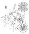
- Restraining system 6 includes control interface 8 operatively coupled to peg and boot interface 10. Control interface 8 is separated from interface 10 meaning that may be remote or spaced at some distance and/or be a physically separate part from interface 10.
- control interface 8 is coupled to a handlebar of motorcycle 2 and may include a finger-actuated switch.
- control interface device 8 is located in a helmet and may be sound activated (e.g., via a microphone).
- control interface 8 has portions in a plurality of locations such as both the handlebar and the helmet. Other locations and embodiments of control interface 8 are possible such as in boot 10A.
- Control interface device 8 is configured to receive an input from rider 4.
- the input is the finger-actuated closing and/or opening of a switch.
- the input is a voice received by a microphone.
- the input may be received in any one of a plurality of different ways, such as a finger input, a pressing of a button, a twisting of a dial, a twisting of a wrist, and a foot actuation to name a few examples.
- control interface 8 is configured to receive a wireless signal that is remote from motorcycle 2.
- the wireless signal is a GPS locator signal that may be indicative of a location along a race course. From here forward, the control interface 8 will be described as receiving first and second inputs from rider 4 but it is to be understood that control interface 8 may also receive the first and second inputs from an external source of wireless signals.
- the peg/boot interface 10 is configured to restrain boot 10A to peg 10B in response to a first input from rider 4 to control interface 8.
- the peg/boot interface is configured to release boot 10A from peg 10B in response to a second input from rider 4 to control interface 8.
- interface 10 includes a restraining device 14 that is configured to couple to a restraining feature 18 in response to the first input to control interface 8.
- restraining device 14 is primarily configured to restrain translational (but not necessarily rotational) motion of boot 10A relative to peg 10B along a z-axis that is generally aligned with a long axis of lower leg of rider 4.
- Restraining device 14 may allow other motion of boot 10A relative to peg 10B such as rotation along other axes such as an x-axis that is parallel to the long axis of peg 10B (coming out the page in FIG. 1 ).
- boot 10A may be restrained along other axes such as a gravitational axis.
- Restraining device 14 is mounted proximate to foot peg 10B meaning that it is mounted upon or in close proximity to foot peg 10B. In the case of a bicycle, restraining device 14 is mounted upon a bicycle pedal 10B.
- Restraining system 6 includes control electronics 12 coupled to control interface 8 and restraining device 14 and receives power from power source 16.
- control interface 8 transmits a signal to control electronics 12 wirelessly.
- control interface 8 is coupled to control electronics 12 by a signal wire.
- Control electronics 12 are configured to operate and change a state of restraining device 14 in response to receiving inputs from control interface 8. In response to receiving a first input from control interface 8, control electronics 12 are configured to activate restraining device 14 whereby restraining device 14 mechanically couples to complementary boot restraining feature 18.
- Boot restraining feature 18 is referred to as complementary relative to restraining device 14 because they form an effective interface 10 whereby restraining feature 18 is secured to restraining device 14 in response to the first input.
- control interface 8 is configured to control restraint for both the left and right boots simultaneously. In a second embodiment, the control interface 8 is configured to control restraint for the left and right boots independently. In a preferred embodiment, the restraining feature 14 is the same for both left and right boots. In an alternative embodiment, different restraining features 14 are used for the left and right boots. In a preferred embodiment the control electronics 12 are coupled to a sensor or feedback device that is incorporated into restraining device 14 to indicate whether or not each boot has been properly restrained.
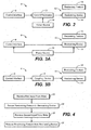
- control interface 8 is a switch that opens and closes a circuit formed between power source 16 and restraining device 14.
- switch 8 When switch 8 is closed, power is coupled to restraining device 14 that then secures restraining feature 18 to restraining device 14.
- switch 8 When switch 8 is open, restraining device 14 is in a released state whereby restraining feature 18 is not secured to restraining device 14.
- FIG. 3B A second alternative embodiment of restraining system 6 is depicted in block diagram form in FIG. 3B .
- control interface 8 is coupled to restraining device 14 via a coupling device 9 (depicted as a dashed line in FIG. 1 ) when restraining device 14 is remote or spaced from control interface 8.
- coupling device 9 is mechanical in nature and may include a cable, a lever, a gear train, or a combination thereof that provides mechanical coupling between control interface 8 and restraining device 14.
- coupling device 9 is pneumatic in design and includes one or more air pressure lines that couple control interface 8 to restraining device 14.
- coupling device 9 includes one or more conductive wires that couple control interface 8 to restraining device 14.
- coupling device 9 includes a wireless link that couples control interface 8 to restraining device 14.
- Restraining device 14 is spaced from or remote from control interface 8 in that they are not integrated into the same component.
- restraining device 14 is integral to peg 10B while control interface 8 is physically separate from peg 10B.
- Physically separated, spaced or remote in the context of this invention may be a small separation or it may indicate nearly opposite end portions of the motorcycle, or a location remote from the motorcycle.
- FIG. 2 Yet another alternative embodiment relative to FIG. 2 utilizes an air logic circuit rather than an electrical circuit for controlling a pneumatic restraining device 14.
- the air logic circuit is responsive to inputs to control interface 8 and may use air pressure rather than electrical power to operate restraining device 14.
- Power source 16 can optionally be an air pressure source 16 that provides logical responses to inputs from control interface 16 and provides pneumatic power to restraining device 14.
- control interface 8 may provide an electrical signal that is utilized by restraining device 14, which in turn fixates the restraining feature 18 pneumatically.
- restraining device 14 is located on boot 10A and restraining feature 18 is located on peg 10B.
- boot 10A may include the control electronics 12 and the power source 16 depicted in FIG. 2 .
- the control interface 8 receives a first input from rider 4.
- the input may be in the form of a button 8A being pushed or it may be in the form of a voice input to a microphone 8B.
- an input may include other actions by rider 4 such as the moving of a lever or dial.
- the first input is transmitted from control interface 8 to control electronics 12 wirelessly, by a wired connection, pneumatically, or by a mechanical connection.
- control electronics 12 or a coupling device 9 activates the restraining device 14 to secure the restraining feature 18 to the restraining device 14 according to step 22.
- the rider may be passing over a jump and/or rough terrain on motorcycle 2 after which the rider may want to release boot 10A from peg 10B.
- control interface 8 receives a second input from rider 4. According to 26, the restraining device 14 releases the restraining feature 18 in response to the second input.
- first and second inputs may be wireless inputs received by control interface 8.
- restraining system 6 including a restraining device 14 and restraining feature 18 will be discussed with figures focusing in on the interface 10.
- the various embodiments of restraining device 14 will be referred to as 14-1 for the first embodiment, 14-2 for the second embodiment, and so on.
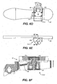
- FIGS. 5A-G A first embodiment of interface 10 is depicted in FIGS. 5A-G wherein restraining device 14-1 includes an electromagnet 30 (see FIG. 5C ).
- FIG. 5A is an isometric view of boot 10A secured to peg 10B containing electromagnet 30.
- FIG. 5B is a side view and
- FIG. 5C is a cross section taken through section lines 5C-5C of FIG. 5B .
- Boot 10A includes a magnetic plate or magnet 32 integrated into sole 34.
- the magnet or magnetic plate 32 may include one or more of a number of materials that may be metallic, non-metallic, polymeric, hard plastic, ceramic, or any combination thereof.
- the plate 32 is located proximate to a location of peg 10B when rider 4 positions boot 10A on peg 10B.
- Peg 10B includes electromagnet 30 (see FIG. 5C ) that is configured to attract plate 32 when activated (when it receives current).
- FIG. 5D is an end view of boot/peg interface 10 and FIG. 5E is a cross section taken through section 5E-5E of FIG. 5D .
- FIG. 5F depicts a detailed cross section view of interface 10 taken through portion 5F-5F of FIG. 5C .
- FIG. 5G depicts a detailed cross section view of interface 10 taken through portion 5G-5G of FIG. 5E .
- FIGS. 5F and 5G in particular illustrate some additional aspects of the electromagnet embodiment 30 of restraining device 14-1.
- peg 10B has a rotational mount 36 relative to the motorcycle, allowing the electromagnet 30 to rotate relative to plate 32.
- a spring load mount 42 of electromagnet 30 relative to a housing 44 that biases the electromagnet 30 upwardly to assure a close proximity between electromagnet 30 and plate 32.
- a first input is received by control interface 8 from rider 4.
- a first signal is sent to control electronics 12 that activate (provide current to) electromagnet 30, self-aligning and securing metal plate 32 to electromagnet 30.
- control interface 8 receives a second input from rider 4.
- a second signal is sent to control electronics 12 that respond by shutting down the current to electromagnet 30, thereby releasing plate 32 from electromagnet 30.
- restraining feature 18 includes an opening formed into the bottom of a boot sole configured to receive an extendable portion from restraining device 14-2.
- the opening preferably has a reentrant geometry, which enables locking between the extendable portion and the opening.
- An example of a reentrant geometry is a hole or channel with a lip proximate to an exit to the hole.
- the extendable portion preferably has a widened top portion, which interferes with and is caught by the lip in a locking configuration. To unlock this configuration, the extendable portion is turned, collapsed, and/or translated to eliminate the interference between the top and the lip.
- the hole or opening can be of any geometry such as circular, square, rectangular, etc.
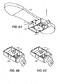
- FIG. 6A is an isometric view of a boot sole 50 and a peg 10B that incorporates restraining device 14-2 utilizing a locking pin 52 (see FIGS. 6B, 6C).
- FIG. 6B depicts the restraining device 14-2 in a locked state (with locked pin 52L)
- FIG. 6C depicts the restraining device 14-2 in an unlocked state (with unlocked pin 52U).
- pin 52U has it sides parallel with and fitting between sides of channel 54 so that pin 52 can be readily inserted and removed from channel 54.
- the corners of pin 52L overlap the sides of channel 54 thereby restraining pin 52 from being pulled out of channel 54.
- FIG 6D is a bottom view of interface 10 depicting a mechanism for locking and unlocking pin 52 including a spring 56 and a cable 58.
- Spring 56 exerts a torque on a shaft of pin 52 that urges pin 52L toward the locked state.
- Actuation cable 58 is configured to exert an opposing torque on the shaft of pin 52 that rotates pin 52U to the unlocked state.
- FIG. 6E depicts a side view of the boot sole 50 and peg 10B.
- FIG. 6F depicts a detailed cross sectional view taken through 6F-6F of FIG 6E .
- pin 52L is shown in a locked state in channel 54.
- Pin spring 56 maintains pin 52 in the locked state.
- Interface 10 also includes a spring 58 configured to bias the pin 52 into an up position so that it will engage the channel 54 when the rider positions channel 54 on peg 10B.
- pin 52 is initially in the locked state but is outside of the boot channel 54, which is resting upon pin 52.
- pin 52 is momentarily rotated from a locked to an unlocked state, aligning pin 52 with channel 54.
- spring 58 can then displace pin 52 up into channel 54.
- pin 52 rotates back to the locked state in response to the force of spring 56.
- the pin again rotates to an unlocked state to allow rider 4 to lift boot 10A away from being restrained.
- the restraining feature is an upstanding member or a latch feature positioned on the sole of the boot 10A.
- the restraining device 14-3 includes a latching device configured to latch to the upstanding member in response to the first input received by control device 8.
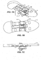
- FIGS. 7A-E depict a particular example of this third exemplary embodiment of interface 10 including a latch assembly 70 configured to fixedly couple to a boot rail 72.
- FIG. 7A is an isometric view looking up at boot sole 74 resting upon peg 10B. Within peg 10B is latch assembly 70 that is coupled to boot rail 72.
- FIG. 7B is a bottom view and FIG. 7C is a side view of the sole 74, boot rail 72, and latch assembly 70.
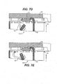
- FIGS. 7D and 7E are cross section views of the locked and unlocked states respectively of interface 10 taken through section 7D-7D of FIG. 7C .
- Latch assembly 70 includes a combination of a fixed arm 76 and a rotating latch arm 78.
- FIG. 7D depicts a locked (latched) state of interface 10 in which boot rail 72 is captured between fixed arm 76 and rotating arm 78.
- FIG. 7E depicts an unlocked (unlatched) state of interface 10 in which the fixed arm 76 and rotating arm 78 are relatively separated from each other and the boot rail is free.
- an actuator (part of restraining device 14-3) rotates arm 78 to capture boot rail 72 as in FIG. 7D .
- the actuator rotates arm 78 to release boot rail 72 as in FIG .7E .
- both of latch features 76 and 78 are configured to rotate inwardly and outwardly. In response to a first input latch features 76 and 78 rotate together to converge upon and latch upon rail 72 as in FIG. 7D . In response to a second input latch features 76 and 78 separate from each other to release boot rail 72.
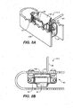
- FIGS. 8A and 8B depict a fourth exemplary embodiment of restraining device 14-4 that includes a spring loaded latch assembly 80 configured to engage a channel (not shown, similar to channel 54 in FIG. 6A ) formed into the sole of a boot.
- FIG. 8A is an isometric view and FIG. 8B is a top view of boot peg 10B having latch assembly 80 within.
- Latch assembly 80 includes a fixed bracket 84 and a rotating latch bracket 86.
- Torsion spring 88 urges rotating latch bracket 86 toward an outward position that is away from fixed bracket 84.
- Actuation cable 90 is coupled to rotating latch bracket 86 such that pulling on actuation cable 90 with sufficient force rotates rotating latch bracket 86 toward fixed bracket 84.
- boot 10A presses down against latch assembly 80. Because torsion spring 88 urges rotating latch bracket outwardly it cannot enter the boot channel (not shown). However, when actuation cable 90 is momentarily activated (first input from rider 4), torsion spring 88 is counteracted and rotating latch bracket 86 is rotated inwardly, allowing the fixed bracket 84 and the rotating latch bracket 86 to enter the boot channel (not shown). The release of the actuation cable 90 thereby locks latch assembly 80 to the boot 10A.
- the cable 90 is again pulled (second input from rider 4) to rotate the rotating latch bracket 86 toward fixed bracket 84. While the cable 90 is under tension, the rider 4 may release boot 10A from latch assembly 80.
- FIGS. 9A-C depict a fifth embodiment of restraining device 14-5 that includes a telescoping latch assembly 92 integrated into peg 10B.
- Telescoping latch assembly 92 includes latch tower 93 and lift cam 94. Within latch tower 93 is drive pin 96, bias spring 98, and latch fingers 100.
- the tower Prior to activation of telescoping latch assembly 92, the tower is in a "down position" so as not to interfere with a boot 10A (not shown). Prior to activation the bias spring 98 biases latch fingers 100 inwardly together.
- latch assembly 92 Upon activation of latch assembly 92 (first input from rider 4), lift cam 94 is rotated and thereby begins to raise latch tower 93 in an upward direction along the z axis. Latch fingers 100 are lifted along with latch tower 93 and enter boot channel 102. Latch fingers 100 are lifted until they reach an upper limit in boot channel 102. Cam 94 also pushes up drive pin 96, which continues to rise after the latch fingers 100 have reached the upper limit in boot channel 102. Pin 96 then forces fingers 100 apart so that they lock or latch into boot channel 102.
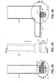
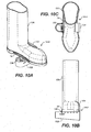
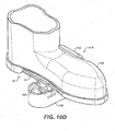
- FIGS. 10A-D depict a sixth embodiment of restraining device 14-6 within interface 10.
- a boot 10A is secured to peg 10B utilizing an arcuate fixed inner extension 104 that cooperates with a rotating latch 106.
- boot 10A is placed under arcuate fixed inner extension 104 so that the arcuate extension 104 curves up and over a portion of boot 10A.
- the rotating latch 106 rotates over and captures a lip or top of boot sole 34 thus locking or latching boot 10A to peg 10B.
- the rotating latch 106 rotates out of engagement from boot sole 34, releasing boot 10A.
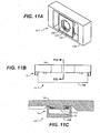
- FIGS. 11A-C depict a seventh embodiment of restraining device 14-7 within interface 10.
- FIG. 11 is an isometric view;
- FIG. 11B is a side view;
- FIG. 11C is cross section 11C-11C taken from FIG. 11B .
- Restraining device 14-7 includes a rotatable keyway plate 107 having an opening 108 that includes notches 109 in plate 107 that have a keying effect relative to a boot cleat 110.
- the boot cleat 110 has a complementary shape relative to opening 108 with two keys 111 that allow boot cleat 110 to be inserted into opening 108 when (and only when) the keys 111 are aligned with notches 109.
- the boot cleat 110 is passed into opening 108 while keys 111 are aligned with notches 109. Then, rotating keyway plate 107 is rotated so that notches 109 are no longer in alignment with keys 111. This locks boot sole 34 to peg 10B. To unlock boot sole 34, the keyway plate 107 is then rotated to align notches 109 with keys 111 so that boot cleat 110 may be lifted out of opening 108.
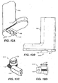
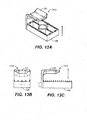
- FIGS. 12A-D depict an eighth embodiment of restraining device 14-8 for restraining boot 10A to cleat 10B.
- FIG. 12A is an isometric looking up at peg 10B and boot 10A.
- FIG. 12B is a side view of boot 10A on peg 10B.
- FIG. 12C is an isometric view and
- FIG. 12D is a side view of restraining device embodiment 14-8 that is incorporated into boot peg 10B.
- a motor 116 is coupled to a worm gear 118 that in turn rotates a locking pin 120 that is similar to pin 52 discussed with respect to FIGS. 6A-F .
- Boot 10A has a channel (not shown) in sole 34 similar to channel 54 of FIGS. 6A , 6D, and 6F .
- the boot sole 34 is placed upon peg 10B.
- restraining device 14-8 is activated whereby pin 120 is aligned with the channel (not shown) in sole 34 and then rotated by ninety degrees to lock pin 120 to the boot sole 34.
- the locking pin 120 is rotated by ninety degrees from the locked position to free the boot sole 34 from peg 10B.
- the pin does not rotate a full ninety degrees from the unlocked to locked position but may rotate any angular amount in response to the first and second inputs to effectively lock and unlock sole 34 relative to peg 10B.
- FIGS. 13A-C depict restraining device embodiment 14-9.
- FIG. 13A is an isometric view
- FIG. 13B is an end view
- FIG. 13C is a side view.
- Restraining device 14-9 includes a top portion 122 overhanging foot peg 10B so that a boot 10A (not shown) can be inserted between top portion 122 and foot peg 10B.
- Top portion 122 is restrained relative to foot peg 10B so as to provide the restraint to boot 10A relative to foot peg 10B along the Z-axis.
- FIGS. 14A-D depicts a tenth embodiment of restraining device 14-10.
- FIG. 14A is an isometric view and
- FIG. 14B is a side view of restraining device 14-10 in a closed position over foot peg 10B.
- FIG. 14C is an isometric view and
- FIG. 14D is a side view of restraining device 14-10 in an open position relative to foot peg 10B.
- Restraining device 14-10 includes vertical support member 124 that is fixedly coupled to foot peg 10B.
- a horizontal restraining portion 126 is rotatingly coupled to vertical support member 124 via hinge 128.
- an actuator (not shown) that is coupled to control interface 8.
- the actuator (not shown) is configured to rotate horizontal restraining member from an open configuration ( FIGS. 14C, D ) to a closed configuration ( FIGS. 14A, B ) in response to a first input received by control interface 8 from rider 4.
- the actuator (not shown) is configured to rotate horizontal restraining portion 126 from the closed configuration ( FIGS. 14A, B ) to an open configuration ( FIGS. 14C, D ) in response to a second input received by control interface 8 from rider 4.
- a rider 4 places his boot 10A (not shown) on foot peg 10B. Before activating device 14-10, the horizontal restraining portion 126 is in a vertical orientation as depicted in FIGS. 14C , D.
- an actuator (not shown) rotates horizontal restraining portion 126 from the vertical orientation to a horizontal orientation as depicted in FIGS. 14A , B.
- the actuator (not shown) rotates horizontal restraining portion 126 back to the vertical orientation as depicted in FIGS. 14C , D.
- an electromagnet similar to the embodiment described with respect to FIGS. 5A-G may be used in combination with a pin embodiment similar to that described with respect to FIGS. 6A-E .
- the electromagnet may serve the purpose of helping to align a boot channel with a pin.
- an electromagnet similar to the embodiment described with respect to FIGS. 5A-G may be used in combination with a latch embodiment similar to that described with respect to FIGS. 7A-E .
- the electromagnet in this case would help to align the boot rail with the latch.
- a permanent magnet may be used in combination with either of the second ( FIGS. 6A-E ) or third ( FIGS. 7A-E ) embodiments to facilitate alignment between the restraining device 14 and the restraining feature 18.
- the restraining system 6 of the present invention provides considerable advantages to the rider 4 of a motorcycle 2 over prior art systems. Rider 4 can quickly and easily restrain or disengage boot 10A to peg 10B using control interface 8. Over rough terrain or jumps the rider 4 now has much greater control over the motorcycle. 2 when boot 10A is restrained to peg 10B. Moreover, the system 6 can be quickly disengaged to release boot 10A from peg 10B when rider 4 prefers to operate the motorcycle in a more conventional mode. When restraining system 6 is thus disengaged, the restraining device 14 is hardly noticeable to the rider 4.
Landscapes
- Engineering & Computer Science (AREA)
- Mechanical Engineering (AREA)
- Chemical & Material Sciences (AREA)
- Combustion & Propulsion (AREA)
- Transportation (AREA)
- Footwear And Its Accessory, Manufacturing Method And Apparatuses (AREA)
- Mechanical Control Devices (AREA)
- Lock And Its Accessories (AREA)
- Professional, Industrial, Or Sporting Protective Garments (AREA)
- Passenger Equipment (AREA)
Claims (10)
- Système de restriction d'une chaussure de motocycliste à un cale-pied de véhicule, comprenant :un dispositif de restriction (14) ; etune interface de commande (8) couplée au dispositif de restriction (14) et conçue pour recevoir une entrée, le dispositif de restriction (14) étant conçu pour restreindre la chaussure par rapport au cale-pied en réponse à l'entrée,caractérisé en ce que l'interface de commande (8) est montée sur un guidon ; ou sur un casque de motocycliste.
- Système selon la revendication 1, dans lequel le dispositif de restriction (14) est monté :sur un repose-pied d'une moto ; ouà proximité d'un repose-pied d'une moto ; ousur la pédale d'un vélo.
- Système selon la revendication 1, dans lequel le dispositif de restriction (14) comprend un élément parmi un électroaimant, un verrou rotatif, un cliquet linéaire ou un cliquet rotatif.
- Système selon la revendication 1, comprenant en outre une chaussure possédant une semelle (34) et un accessoire de restriction couplé à la semelle (34), le dispositif de restriction (14) étant conçu pour se coupler à ou se détacher de l'accessoire de restriction en réponse à l'entrée ; et l'accessoire de restriction comprenant de préférence un élément parmi une plaque métallique, un aimant (32), une plaque magnétique, une plaque non métallique, un orifice dans la semelle, un accessoire mécanique proéminent ou un tasseau s'étendant depuis la semelle.
- Système selon la revendication 1 comprenant en outre un dispositif de couplage (9) qui couple le dispositif de restriction (14) à l'interface de commande (8) ; le dispositif de couplage (9) étant de préférence un élément parmi un fil physique, un lien de signalisation sans fil, un câble, un levier et un passage d'air comprimé.
- Système selon la revendication 1, dans lequel l'interface de commande (8) est conçu pour recevoir l'entrée de la part du motocycliste ; et l'entrée du motocycliste est un élément parmi la pression d'un bouton, une commande vocale, le fait de tourner un cadran ou d'actionner un levier.
- Système selon la revendication 1, dans lequel l'interface de commande (8) est conçue pour recevoir l'entrée de la part d'une source sans fil.
- Système selon la revendication 1, dans lequel le dispositif de restriction (14) est conçu pour restreindre la chaussure du motocycliste en réponse à une première entrée et pour relâcher la chaussure du motocycliste en réponse à une seconde entrée.
- Procédé de restriction d'une chaussure d'un motocycliste à un cale-pied de véhicule, comprenant :la prévision d'un dispositif de restriction à proximité du cale-pied;la prévision d'une interface de commande séparée de mais couplée à un dispositif de restriction ;la réception d'une entrée au niveau de l'interface de commande ; etl'activation du dispositif de restriction pour restreindre la chaussure du motocycliste au cale-pied en réponse à l'entrée ;dans lequel l'interface de commande est montée sur un guidon ou sur un casque de motocycliste.
- Procédé selon la revendication 10, dans lequel
la réception de l'entrée est une réception parmi la réception d'une commande vocale, la réception d'une activation d'interrupteur par un doigt, la réception d'une activation d'un levier à la main, la réception d'une rotation de cadran et la réception d'un signal sans fil ; ou
l'activation du dispositif de restriction inclut la transmission d'un signal par l'interface de commande au dispositif de restriction ; ou
l'activation du dispositif de restriction inclut la transmission de l'entrée par une ou plusieurs transmissions parmi une transmission mécanique, une transmission pneumatique, une transmission électrique ou un signal sans fil.
Applications Claiming Priority (2)
| Application Number | Priority Date | Filing Date | Title |
|---|---|---|---|
| US31410310P | 2010-03-15 | 2010-03-15 | |
| PCT/US2011/028544 WO2011116008A1 (fr) | 2010-03-15 | 2011-03-15 | Système de retenue activé par interface de commande pour attacher des chaussures de motocycliste à un repose-pieds |
Publications (3)
| Publication Number | Publication Date |
|---|---|
| EP2547577A1 EP2547577A1 (fr) | 2013-01-23 |
| EP2547577A4 EP2547577A4 (fr) | 2014-09-17 |
| EP2547577B1 true EP2547577B1 (fr) | 2015-12-16 |
Family
ID=44558675
Family Applications (1)
| Application Number | Title | Priority Date | Filing Date |
|---|---|---|---|
| EP11756871.7A Not-in-force EP2547577B1 (fr) | 2010-03-15 | 2011-03-15 | Systeme de retenue active par interface de commande pour attacher des chaussures de motocycliste a un repose-pieds |
Country Status (6)
| Country | Link |
|---|---|
| US (1) | US9038502B2 (fr) |
| EP (1) | EP2547577B1 (fr) |
| AU (1) | AU2011227408A1 (fr) |
| CA (1) | CA2792821A1 (fr) |
| ES (1) | ES2561436T3 (fr) |
| WO (1) | WO2011116008A1 (fr) |
Cited By (1)
| Publication number | Priority date | Publication date | Assignee | Title |
|---|---|---|---|---|
| CN113165720A (zh) * | 2018-11-30 | 2021-07-23 | 金度莹 | 配备有可移动的磁性自行车踏板及防止铁粉附着装置的鞋连接装置 |
Families Citing this family (24)
| Publication number | Priority date | Publication date | Assignee | Title |
|---|---|---|---|---|
| WO2010017592A1 (fr) * | 2008-08-13 | 2010-02-18 | Ben Aaron Donaldson | Chaussure |
| US20110239817A1 (en) * | 2010-03-30 | 2011-10-06 | Ming-Hui Chang | Detachable mechanism of bicycle pedal and locking shoe |
| TW201143657A (en) * | 2010-06-11 | 2011-12-16 | Haka Co Ltd | Cycling shoe |
| US8794106B2 (en) * | 2011-08-31 | 2014-08-05 | Evolution Racing Products, Llc | Mechanical restraint for securing motorcycle rider footwear to footpeg |
| DE102012201403B4 (de) * | 2012-02-01 | 2022-01-05 | Robert Bosch Gmbh | Fahrrad mit zumindest einem Klickpedal |
| GB2500063A (en) * | 2012-03-09 | 2013-09-11 | Jason Mcinulty | Motorcycle footwear sole |
| US9545972B2 (en) * | 2012-04-13 | 2017-01-17 | David Delon Williams | Variable magnetic binding system for bicycle pedal |
| US10982751B2 (en) | 2013-01-25 | 2021-04-20 | Sram, Llc | Control device for bicycle and methods |
| US20140224062A1 (en) * | 2013-02-11 | 2014-08-14 | Vp Concepts Llc | Bicycle pedal system |
| US9499231B2 (en) * | 2013-03-14 | 2016-11-22 | Speedplay, Inc. | Pedal and cleat assembly |
| TWI613114B (zh) * | 2014-07-25 | 2018-02-01 | 睿能創意公司 | 遠端致動型交通工具腳踏板 |
| KR101702189B1 (ko) * | 2014-12-31 | 2017-02-02 | 박전진 | 자전거용 페달 구동장치 |
| FR3053954B1 (fr) * | 2016-07-13 | 2019-11-22 | Yannick Adam | Pedale intuitive |
| US10897948B2 (en) * | 2016-08-09 | 2021-01-26 | Ben Donaldson | Footwear roofing shoes |
| CN106627959B (zh) * | 2017-01-04 | 2019-04-02 | 京东方科技集团股份有限公司 | 一种锁踏及锁踏控制方法 |
| CZ2017323A3 (cs) * | 2017-06-06 | 2018-12-19 | Karel Hršel | Cyklistický pedál se zarážkou |
| US10106222B1 (en) * | 2017-06-06 | 2018-10-23 | Jakob Kai Teksler | Pedal apparatus with actuator configured to apply variable pressures |
| US11130547B2 (en) | 2019-11-04 | 2021-09-28 | Houston Partners, LLC | Systems and methods associated with magnetically activated mechanical binding for pedals |
| US12110077B2 (en) * | 2020-06-25 | 2024-10-08 | Michael Andrew LAVINE | Computerized bicycle pedal lock-in and release system and method |
| US12128988B2 (en) * | 2020-09-11 | 2024-10-29 | Bradley M. Ganz | Cadence based shoe-pedal coupling system |
| US11834129B2 (en) * | 2021-06-25 | 2023-12-05 | Ravindran Meadows | Smart self-locking magnetic bike pedal |
| AU2022440631A1 (en) * | 2022-02-15 | 2024-09-05 | Australian Sports Commission | Bicycle platform |
| DE102022115958B4 (de) | 2022-06-27 | 2024-05-23 | Gabriela Born | Pedalsystem für ein Fahrrad |
| WO2026078420A1 (fr) * | 2024-10-10 | 2026-04-16 | Ascencio Cucuma Fernando | Mécanismes pour le pédalage de bicyclettes avec le talon |
Family Cites Families (32)
| Publication number | Priority date | Publication date | Assignee | Title |
|---|---|---|---|---|
| NL8203406A (nl) * | 1982-08-31 | 1984-03-16 | Lassche Jakob | Rijwielpedaal met voethouder. |
| US4458910A (en) * | 1982-09-29 | 1984-07-10 | Stillwagon Steven R | Foot retainer |
| US4640151A (en) * | 1984-02-27 | 1987-02-03 | Howell Richard J | Bicycle pedalling apparatus |
| US4809563A (en) * | 1987-10-21 | 1989-03-07 | Duane Loppnow | Bicycle pedal |
| DE3822663A1 (de) * | 1988-07-05 | 1990-01-11 | Fichtel & Sachs Ag | Pedal-bindung |
| JPH0274490A (ja) * | 1988-09-09 | 1990-03-14 | Shimano Ind Co Ltd | 自転車用ペダル |
| US4932287A (en) * | 1988-11-07 | 1990-06-12 | Dennis Ramos | Combined shoe and pedal for sports bicycle |
| US5097687A (en) * | 1990-10-24 | 1992-03-24 | Turrin David J | Releasable toe strap for a bicycle pedal |
| US5259270A (en) * | 1992-12-30 | 1993-11-09 | Lin Wen Hwa | Bicycle pedal |
| BE1008279A3 (nl) * | 1994-01-25 | 1996-03-05 | Merckx Eddy Equip Nv | Fietspedaal. |
| FR2777857B1 (fr) | 1998-04-27 | 2000-06-23 | Look Cycle | Dispositif de fixation rapide d'une chaussure sur une pedale de bicyclette |
| FR2795381B1 (fr) * | 1999-06-25 | 2001-09-28 | Look Cycle Int | Pedale automatique de cycle |
| US6543310B1 (en) * | 2000-04-03 | 2003-04-08 | Thomas Baker | Bicycle pedal clip and mounting apparatus |
| US7258192B2 (en) * | 2000-11-21 | 2007-08-21 | American Off-Road Technologies Llc | Two person RUV with ergonomic seating and feet placement |
| AU2002255568B8 (en) * | 2001-02-20 | 2014-01-09 | Adidas Ag | Modular personal network systems and methods |
| WO2003070548A1 (fr) * | 2002-02-22 | 2003-08-28 | Bombardier Recreational Products Inc. | Pieces pour vehicule a trois roues permettant au conducteur de se pencher |
| US6957821B2 (en) * | 2003-01-17 | 2005-10-25 | Mark Gorman | Safety device for motorcycle foot pegs |
| US7073409B2 (en) * | 2003-05-22 | 2006-07-11 | Hsiao-Chin Ho | Pedal device |
| US6783139B1 (en) * | 2003-07-08 | 2004-08-31 | Chien-Kuo Wang | Bicycle having dual-purpose pedal |
| US7178272B2 (en) * | 2004-07-22 | 2007-02-20 | Jin-Long Xie | Snap block structure for bicycle-use shoes |
| US7021175B1 (en) * | 2004-07-29 | 2006-04-04 | Jin-Long Xie | Racing type pedal for bicycle |
| CA2485324A1 (fr) | 2004-11-16 | 2006-05-16 | Yvan Champoux | Methode et appareil pour la mesure in situ du mouvement angulaire des pedales automatiques commerciales |
| US20060248965A1 (en) * | 2005-05-06 | 2006-11-09 | Wyatt Roland J | Systems and methods of power output measurement |
| US20080179589A1 (en) * | 2005-05-26 | 2008-07-31 | Us Government As Represented By Secretary Of The Army | Systems, devices and methods involving superlattice infrared detector structures |
| US7757583B1 (en) * | 2005-11-03 | 2010-07-20 | Reading Randall C | Power floor boards |
| US7644521B2 (en) * | 2006-04-03 | 2010-01-12 | Ariat International, Inc. | Footwear with rest support |
| US7788828B2 (en) * | 2006-05-10 | 2010-09-07 | Krouse Wayne F | Active shoe cleat system |
| US7581338B1 (en) * | 2006-09-11 | 2009-09-01 | Housley Jr Norman A | Boot mounted shifting and breaking device |
| US20080179859A1 (en) | 2007-01-25 | 2008-07-31 | Boehmke Steven L | Motorcycle foot peg and boot cleat assembly |
| JP2008221880A (ja) * | 2007-03-08 | 2008-09-25 | Willcom Inc | 位置情報送信装置を内蔵した自転車のペダル及び自転車の位置情報を提供する移動通信システム |
| AU2009201030A1 (en) * | 2008-03-14 | 2009-10-01 | Vulcan Global Manufacturing Solutions, Inc. | Stirrup |
| US7874885B2 (en) * | 2008-07-25 | 2011-01-25 | Shimano Inc. | Rowing boat foot support assembly |
-
2011
- 2011-03-15 AU AU2011227408A patent/AU2011227408A1/en not_active Abandoned
- 2011-03-15 US US13/048,722 patent/US9038502B2/en active Active
- 2011-03-15 ES ES11756871.7T patent/ES2561436T3/es active Active
- 2011-03-15 CA CA2792821A patent/CA2792821A1/fr not_active Abandoned
- 2011-03-15 WO PCT/US2011/028544 patent/WO2011116008A1/fr not_active Ceased
- 2011-03-15 EP EP11756871.7A patent/EP2547577B1/fr not_active Not-in-force
Cited By (3)
| Publication number | Priority date | Publication date | Assignee | Title |
|---|---|---|---|---|
| CN113165720A (zh) * | 2018-11-30 | 2021-07-23 | 金度莹 | 配备有可移动的磁性自行车踏板及防止铁粉附着装置的鞋连接装置 |
| EP3889023A4 (fr) * | 2018-11-30 | 2022-08-03 | Do Young Kim | Pédale de bicyclette de type à aimant mobile, et dispositif de couplage de chaussure équipé d'un moyen pour empêcher la fixation de poudre métallique |
| CN113165720B (zh) * | 2018-11-30 | 2022-10-18 | 金度莹 | 配备有可移动的磁性自行车踏板及防止铁粉附着装置的鞋连接装置 |
Also Published As
| Publication number | Publication date |
|---|---|
| ES2561436T3 (es) | 2016-02-26 |
| US9038502B2 (en) | 2015-05-26 |
| EP2547577A4 (fr) | 2014-09-17 |
| WO2011116008A1 (fr) | 2011-09-22 |
| AU2011227408A1 (en) | 2012-09-27 |
| US20110219911A1 (en) | 2011-09-15 |
| CA2792821A1 (fr) | 2011-09-22 |
| EP2547577A1 (fr) | 2013-01-23 |
Similar Documents
| Publication | Publication Date | Title |
|---|---|---|
| US9038502B2 (en) | Control interface activated restraining system to secure a rider's footwear to a foot support | |
| US8991838B2 (en) | Stroller frame with an automatic brake mechanism actuatable by hand detecting | |
| EP2913261B1 (fr) | Bicyclette à pédalage assisté et boîtier de batterie | |
| JP4656942B2 (ja) | 慣性による安全システムを備える車両用のドアハンドル | |
| US20090025506A1 (en) | Vehicle Pedal Controls proof against Misapplication of Accelerator | |
| EP1724165B1 (fr) | Contrôleur de véhicule pour véhicule du type monté à califourchon | |
| EP2128014A1 (fr) | Dérailleur de bicyclette avec appareil de résistance du mouvement | |
| JP7032074B2 (ja) | 自転車制御装置 | |
| EP1245483A3 (fr) | Dispositif de commande pour bicyclette | |
| JP6255164B2 (ja) | 自転車のギアシフト部のバーエンド型電気作動装置 | |
| US6871380B2 (en) | Wheel device for stroller | |
| TW200524776A (en) | Suspension adjustment actuator apparatus | |
| CN108545129A (zh) | 自行车及其线控定位结构 | |
| JP6839852B2 (ja) | 錠駆動装置及び自転車錠装置 | |
| JP2006056505A (ja) | 車両のパーキングレバーシステム | |
| AU715882B2 (en) | Single-pedal system in motor vehicles and a method for forming such a single-pedal system | |
| EP1273510A3 (fr) | Dispositif pour guidon de bicyclette, moyeu de bicyclette, et dispositif antivol connectant de tels dispositifs | |
| CN103620515B (zh) | 联动操作机构 | |
| CN210391391U (zh) | 一种带拉索解锁机构的电子转向锁系统 | |
| JP6199146B2 (ja) | 電動アシスト自転車 | |
| TW201105545A (en) | A clipless pedal for bicycles | |
| KR101410654B1 (ko) | 악셀페달의 오조작 방지 구조 | |
| JP4819072B2 (ja) | 自動変速操作装置 | |
| KR100900346B1 (ko) | 자전거 안장 지지장치 | |
| CN115726633A (zh) | 机电锁 |
Legal Events
| Date | Code | Title | Description |
|---|---|---|---|
| PUAI | Public reference made under article 153(3) epc to a published international application that has entered the european phase |
Free format text: ORIGINAL CODE: 0009012 |
|
| 17P | Request for examination filed |
Effective date: 20121015 |
|
| AK | Designated contracting states |
Kind code of ref document: A1 Designated state(s): AL AT BE BG CH CY CZ DE DK EE ES FI FR GB GR HR HU IE IS IT LI LT LU LV MC MK MT NL NO PL PT RO RS SE SI SK SM TR |
|
| DAX | Request for extension of the european patent (deleted) | ||
| RIN1 | Information on inventor provided before grant (corrected) |
Inventor name: KLINE, DANIEL, S. Inventor name: ZOUMARAS, STEVEN Inventor name: LIVINGSTON, ADAM Inventor name: BELT, GUSTAF Inventor name: TYVOLL, DAVID Inventor name: EMERSON, JOHN |
|
| A4 | Supplementary search report drawn up and despatched |
Effective date: 20140820 |
|
| RIC1 | Information provided on ipc code assigned before grant |
Ipc: B62J 25/00 20060101ALI20140813BHEP Ipc: B62M 3/00 20060101AFI20140813BHEP Ipc: B62M 3/08 20060101ALI20140813BHEP |
|
| RIN1 | Information on inventor provided before grant (corrected) |
Inventor name: KLINE, DANIEL, S. Inventor name: LIVINGSTON, ADAM Inventor name: TYVOLL, DAVID Inventor name: ZOUMARAS, STEVEN Inventor name: EMERSON, JOHN Inventor name: BELT, GUSTAF |
|
| GRAP | Despatch of communication of intention to grant a patent |
Free format text: ORIGINAL CODE: EPIDOSNIGR1 |
|
| RIC1 | Information provided on ipc code assigned before grant |
Ipc: B62J 25/00 20060101ALI20150527BHEP Ipc: B62M 3/08 20060101ALI20150527BHEP Ipc: B62M 3/00 20060101AFI20150527BHEP |
|
| INTG | Intention to grant announced |
Effective date: 20150625 |
|
| GRAS | Grant fee paid |
Free format text: ORIGINAL CODE: EPIDOSNIGR3 |
|
| GRAA | (expected) grant |
Free format text: ORIGINAL CODE: 0009210 |
|
| AK | Designated contracting states |
Kind code of ref document: B1 Designated state(s): AL AT BE BG CH CY CZ DE DK EE ES FI FR GB GR HR HU IE IS IT LI LT LU LV MC MK MT NL NO PL PT RO RS SE SI SK SM TR |
|
| REG | Reference to a national code |
Ref country code: GB Ref legal event code: FG4D |
|
| REG | Reference to a national code |
Ref country code: CH Ref legal event code: EP |
|
| REG | Reference to a national code |
Ref country code: IE Ref legal event code: FG4D |
|
| REG | Reference to a national code |
Ref country code: AT Ref legal event code: REF Ref document number: 765428 Country of ref document: AT Kind code of ref document: T Effective date: 20160115 |
|
| REG | Reference to a national code |
Ref country code: DE Ref legal event code: R096 Ref document number: 602011022074 Country of ref document: DE |
|
| REG | Reference to a national code |
Ref country code: ES Ref legal event code: FG2A Ref document number: 2561436 Country of ref document: ES Kind code of ref document: T3 Effective date: 20160226 |
|
| REG | Reference to a national code |
Ref country code: FR Ref legal event code: PLFP Year of fee payment: 6 |
|
| REG | Reference to a national code |
Ref country code: NL Ref legal event code: MP Effective date: 20151216 |
|
| REG | Reference to a national code |
Ref country code: LT Ref legal event code: MG4D |
|
| PG25 | Lapsed in a contracting state [announced via postgrant information from national office to epo] |
Ref country code: HR Free format text: LAPSE BECAUSE OF FAILURE TO SUBMIT A TRANSLATION OF THE DESCRIPTION OR TO PAY THE FEE WITHIN THE PRESCRIBED TIME-LIMIT Effective date: 20151216 Ref country code: NO Free format text: LAPSE BECAUSE OF FAILURE TO SUBMIT A TRANSLATION OF THE DESCRIPTION OR TO PAY THE FEE WITHIN THE PRESCRIBED TIME-LIMIT Effective date: 20160316 Ref country code: LT Free format text: LAPSE BECAUSE OF FAILURE TO SUBMIT A TRANSLATION OF THE DESCRIPTION OR TO PAY THE FEE WITHIN THE PRESCRIBED TIME-LIMIT Effective date: 20151216 |
|
| REG | Reference to a national code |
Ref country code: AT Ref legal event code: MK05 Ref document number: 765428 Country of ref document: AT Kind code of ref document: T Effective date: 20151216 |
|
| PG25 | Lapsed in a contracting state [announced via postgrant information from national office to epo] |
Ref country code: GR Free format text: LAPSE BECAUSE OF FAILURE TO SUBMIT A TRANSLATION OF THE DESCRIPTION OR TO PAY THE FEE WITHIN THE PRESCRIBED TIME-LIMIT Effective date: 20160317 Ref country code: FI Free format text: LAPSE BECAUSE OF FAILURE TO SUBMIT A TRANSLATION OF THE DESCRIPTION OR TO PAY THE FEE WITHIN THE PRESCRIBED TIME-LIMIT Effective date: 20151216 Ref country code: LV Free format text: LAPSE BECAUSE OF FAILURE TO SUBMIT A TRANSLATION OF THE DESCRIPTION OR TO PAY THE FEE WITHIN THE PRESCRIBED TIME-LIMIT Effective date: 20151216 Ref country code: SE Free format text: LAPSE BECAUSE OF FAILURE TO SUBMIT A TRANSLATION OF THE DESCRIPTION OR TO PAY THE FEE WITHIN THE PRESCRIBED TIME-LIMIT Effective date: 20151216 Ref country code: RS Free format text: LAPSE BECAUSE OF FAILURE TO SUBMIT A TRANSLATION OF THE DESCRIPTION OR TO PAY THE FEE WITHIN THE PRESCRIBED TIME-LIMIT Effective date: 20151216 Ref country code: NL Free format text: LAPSE BECAUSE OF FAILURE TO SUBMIT A TRANSLATION OF THE DESCRIPTION OR TO PAY THE FEE WITHIN THE PRESCRIBED TIME-LIMIT Effective date: 20151216 |
|
| PG25 | Lapsed in a contracting state [announced via postgrant information from national office to epo] |
Ref country code: CZ Free format text: LAPSE BECAUSE OF FAILURE TO SUBMIT A TRANSLATION OF THE DESCRIPTION OR TO PAY THE FEE WITHIN THE PRESCRIBED TIME-LIMIT Effective date: 20151216 |
|
| PG25 | Lapsed in a contracting state [announced via postgrant information from national office to epo] |
Ref country code: PT Free format text: LAPSE BECAUSE OF FAILURE TO SUBMIT A TRANSLATION OF THE DESCRIPTION OR TO PAY THE FEE WITHIN THE PRESCRIBED TIME-LIMIT Effective date: 20160418 Ref country code: AT Free format text: LAPSE BECAUSE OF FAILURE TO SUBMIT A TRANSLATION OF THE DESCRIPTION OR TO PAY THE FEE WITHIN THE PRESCRIBED TIME-LIMIT Effective date: 20151216 Ref country code: SM Free format text: LAPSE BECAUSE OF FAILURE TO SUBMIT A TRANSLATION OF THE DESCRIPTION OR TO PAY THE FEE WITHIN THE PRESCRIBED TIME-LIMIT Effective date: 20151216 Ref country code: BE Free format text: LAPSE BECAUSE OF NON-PAYMENT OF DUE FEES Effective date: 20160331 Ref country code: IS Free format text: LAPSE BECAUSE OF FAILURE TO SUBMIT A TRANSLATION OF THE DESCRIPTION OR TO PAY THE FEE WITHIN THE PRESCRIBED TIME-LIMIT Effective date: 20160416 Ref country code: RO Free format text: LAPSE BECAUSE OF FAILURE TO SUBMIT A TRANSLATION OF THE DESCRIPTION OR TO PAY THE FEE WITHIN THE PRESCRIBED TIME-LIMIT Effective date: 20151216 Ref country code: SK Free format text: LAPSE BECAUSE OF FAILURE TO SUBMIT A TRANSLATION OF THE DESCRIPTION OR TO PAY THE FEE WITHIN THE PRESCRIBED TIME-LIMIT Effective date: 20151216 Ref country code: EE Free format text: LAPSE BECAUSE OF FAILURE TO SUBMIT A TRANSLATION OF THE DESCRIPTION OR TO PAY THE FEE WITHIN THE PRESCRIBED TIME-LIMIT Effective date: 20151216 |
|
| REG | Reference to a national code |
Ref country code: DE Ref legal event code: R097 Ref document number: 602011022074 Country of ref document: DE |
|
| PLBE | No opposition filed within time limit |
Free format text: ORIGINAL CODE: 0009261 |
|
| STAA | Information on the status of an ep patent application or granted ep patent |
Free format text: STATUS: NO OPPOSITION FILED WITHIN TIME LIMIT |
|
| PG25 | Lapsed in a contracting state [announced via postgrant information from national office to epo] |
Ref country code: PL Free format text: LAPSE BECAUSE OF FAILURE TO SUBMIT A TRANSLATION OF THE DESCRIPTION OR TO PAY THE FEE WITHIN THE PRESCRIBED TIME-LIMIT Effective date: 20151216 Ref country code: DK Free format text: LAPSE BECAUSE OF FAILURE TO SUBMIT A TRANSLATION OF THE DESCRIPTION OR TO PAY THE FEE WITHIN THE PRESCRIBED TIME-LIMIT Effective date: 20151216 Ref country code: MC Free format text: LAPSE BECAUSE OF FAILURE TO SUBMIT A TRANSLATION OF THE DESCRIPTION OR TO PAY THE FEE WITHIN THE PRESCRIBED TIME-LIMIT Effective date: 20151216 Ref country code: LU Free format text: LAPSE BECAUSE OF FAILURE TO SUBMIT A TRANSLATION OF THE DESCRIPTION OR TO PAY THE FEE WITHIN THE PRESCRIBED TIME-LIMIT Effective date: 20160315 |
|
| REG | Reference to a national code |
Ref country code: CH Ref legal event code: PL |
|
| 26N | No opposition filed |
Effective date: 20160919 |
|
| REG | Reference to a national code |
Ref country code: IE Ref legal event code: MM4A |
|
| PG25 | Lapsed in a contracting state [announced via postgrant information from national office to epo] |
Ref country code: BE Free format text: LAPSE BECAUSE OF FAILURE TO SUBMIT A TRANSLATION OF THE DESCRIPTION OR TO PAY THE FEE WITHIN THE PRESCRIBED TIME-LIMIT Effective date: 20151216 |
|
| PG25 | Lapsed in a contracting state [announced via postgrant information from national office to epo] |
Ref country code: IE Free format text: LAPSE BECAUSE OF NON-PAYMENT OF DUE FEES Effective date: 20160315 Ref country code: LI Free format text: LAPSE BECAUSE OF NON-PAYMENT OF DUE FEES Effective date: 20160331 Ref country code: CH Free format text: LAPSE BECAUSE OF NON-PAYMENT OF DUE FEES Effective date: 20160331 |
|
| PG25 | Lapsed in a contracting state [announced via postgrant information from national office to epo] |
Ref country code: SI Free format text: LAPSE BECAUSE OF FAILURE TO SUBMIT A TRANSLATION OF THE DESCRIPTION OR TO PAY THE FEE WITHIN THE PRESCRIBED TIME-LIMIT Effective date: 20151216 |
|
| REG | Reference to a national code |
Ref country code: FR Ref legal event code: PLFP Year of fee payment: 7 |
|
| PG25 | Lapsed in a contracting state [announced via postgrant information from national office to epo] |
Ref country code: MT Free format text: LAPSE BECAUSE OF FAILURE TO SUBMIT A TRANSLATION OF THE DESCRIPTION OR TO PAY THE FEE WITHIN THE PRESCRIBED TIME-LIMIT Effective date: 20151216 |
|
| REG | Reference to a national code |
Ref country code: FR Ref legal event code: PLFP Year of fee payment: 8 |
|
| PG25 | Lapsed in a contracting state [announced via postgrant information from national office to epo] |
Ref country code: HU Free format text: LAPSE BECAUSE OF FAILURE TO SUBMIT A TRANSLATION OF THE DESCRIPTION OR TO PAY THE FEE WITHIN THE PRESCRIBED TIME-LIMIT; INVALID AB INITIO Effective date: 20110315 Ref country code: CY Free format text: LAPSE BECAUSE OF FAILURE TO SUBMIT A TRANSLATION OF THE DESCRIPTION OR TO PAY THE FEE WITHIN THE PRESCRIBED TIME-LIMIT Effective date: 20151216 |
|
| PG25 | Lapsed in a contracting state [announced via postgrant information from national office to epo] |
Ref country code: MT Free format text: LAPSE BECAUSE OF FAILURE TO SUBMIT A TRANSLATION OF THE DESCRIPTION OR TO PAY THE FEE WITHIN THE PRESCRIBED TIME-LIMIT Effective date: 20160331 Ref country code: TR Free format text: LAPSE BECAUSE OF FAILURE TO SUBMIT A TRANSLATION OF THE DESCRIPTION OR TO PAY THE FEE WITHIN THE PRESCRIBED TIME-LIMIT Effective date: 20151216 Ref country code: MK Free format text: LAPSE BECAUSE OF FAILURE TO SUBMIT A TRANSLATION OF THE DESCRIPTION OR TO PAY THE FEE WITHIN THE PRESCRIBED TIME-LIMIT Effective date: 20151216 |
|
| PG25 | Lapsed in a contracting state [announced via postgrant information from national office to epo] |
Ref country code: BG Free format text: LAPSE BECAUSE OF FAILURE TO SUBMIT A TRANSLATION OF THE DESCRIPTION OR TO PAY THE FEE WITHIN THE PRESCRIBED TIME-LIMIT Effective date: 20151216 |
|
| PG25 | Lapsed in a contracting state [announced via postgrant information from national office to epo] |
Ref country code: AL Free format text: LAPSE BECAUSE OF FAILURE TO SUBMIT A TRANSLATION OF THE DESCRIPTION OR TO PAY THE FEE WITHIN THE PRESCRIBED TIME-LIMIT Effective date: 20151216 |
|
| PGFP | Annual fee paid to national office [announced via postgrant information from national office to epo] |
Ref country code: FR Payment date: 20230316 Year of fee payment: 13 |
|
| PGFP | Annual fee paid to national office [announced via postgrant information from national office to epo] |
Ref country code: IT Payment date: 20230310 Year of fee payment: 13 Ref country code: GB Payment date: 20230327 Year of fee payment: 13 |
|
| PGFP | Annual fee paid to national office [announced via postgrant information from national office to epo] |
Ref country code: ES Payment date: 20230406 Year of fee payment: 13 Ref country code: DE Payment date: 20230330 Year of fee payment: 13 |
|
| REG | Reference to a national code |
Ref country code: DE Ref legal event code: R119 Ref document number: 602011022074 Country of ref document: DE |
|
| GBPC | Gb: european patent ceased through non-payment of renewal fee |
Effective date: 20240315 |
|
| PG25 | Lapsed in a contracting state [announced via postgrant information from national office to epo] |
Ref country code: DE Free format text: LAPSE BECAUSE OF NON-PAYMENT OF DUE FEES Effective date: 20241001 |
|
| PG25 | Lapsed in a contracting state [announced via postgrant information from national office to epo] |
Ref country code: GB Free format text: LAPSE BECAUSE OF NON-PAYMENT OF DUE FEES Effective date: 20240315 |
|
| PG25 | Lapsed in a contracting state [announced via postgrant information from national office to epo] |
Ref country code: FR Free format text: LAPSE BECAUSE OF NON-PAYMENT OF DUE FEES Effective date: 20240331 |
|
| PG25 | Lapsed in a contracting state [announced via postgrant information from national office to epo] |
Ref country code: GB Free format text: LAPSE BECAUSE OF NON-PAYMENT OF DUE FEES Effective date: 20240315 Ref country code: FR Free format text: LAPSE BECAUSE OF NON-PAYMENT OF DUE FEES Effective date: 20240331 Ref country code: DE Free format text: LAPSE BECAUSE OF NON-PAYMENT OF DUE FEES Effective date: 20241001 |
|
| PG25 | Lapsed in a contracting state [announced via postgrant information from national office to epo] |
Ref country code: IT Free format text: LAPSE BECAUSE OF NON-PAYMENT OF DUE FEES Effective date: 20240315 |
|
| REG | Reference to a national code |
Ref country code: ES Ref legal event code: FD2A Effective date: 20250506 |
|
| PG25 | Lapsed in a contracting state [announced via postgrant information from national office to epo] |
Ref country code: ES Free format text: LAPSE BECAUSE OF NON-PAYMENT OF DUE FEES Effective date: 20240316 |