EP2547591B1 - Tulipe de visibilité de couvercle - Google Patents
Tulipe de visibilité de couvercle Download PDFInfo
- Publication number
- EP2547591B1 EP2547591B1 EP10795228.5A EP10795228A EP2547591B1 EP 2547591 B1 EP2547591 B1 EP 2547591B1 EP 10795228 A EP10795228 A EP 10795228A EP 2547591 B1 EP2547591 B1 EP 2547591B1
- Authority
- EP
- European Patent Office
- Prior art keywords
- light
- container
- handling device
- tulip
- optical system
- Prior art date
- Legal status (The legal status is an assumption and is not a legal conclusion. Google has not performed a legal analysis and makes no representation as to the accuracy of the status listed.)
- Not-in-force
Links
- 241000722921 Tulipa gesneriana Species 0.000 claims description 96
- 230000003287 optical effect Effects 0.000 claims description 46
- 238000005286 illumination Methods 0.000 claims description 20
- 238000002372 labelling Methods 0.000 claims description 18
- 238000007689 inspection Methods 0.000 claims description 12
- 238000000034 method Methods 0.000 claims description 9
- 230000001681 protective effect Effects 0.000 claims description 9
- 229920003023 plastic Polymers 0.000 claims description 7
- 239000012780 transparent material Substances 0.000 claims description 5
- 239000011521 glass Substances 0.000 claims description 2
- 229920004011 Macrolon® Polymers 0.000 claims 1
- 239000013078 crystal Substances 0.000 claims 1
- 230000001360 synchronised effect Effects 0.000 claims 1
- 238000012856 packing Methods 0.000 description 54
- 238000012545 processing Methods 0.000 description 15
- 238000001514 detection method Methods 0.000 description 11
- 239000006228 supernatant Substances 0.000 description 6
- 238000013461 design Methods 0.000 description 5
- 239000000463 material Substances 0.000 description 5
- 239000004033 plastic Substances 0.000 description 5
- 229920005372 Plexiglas® Polymers 0.000 description 4
- 238000005034 decoration Methods 0.000 description 4
- 239000004926 polymethyl methacrylate Substances 0.000 description 4
- 230000008901 benefit Effects 0.000 description 3
- 238000004891 communication Methods 0.000 description 3
- 238000013016 damping Methods 0.000 description 3
- 230000000694 effects Effects 0.000 description 3
- 238000004049 embossing Methods 0.000 description 3
- 238000003908 quality control method Methods 0.000 description 3
- 239000004020 conductor Substances 0.000 description 2
- 230000008878 coupling Effects 0.000 description 2
- 238000010168 coupling process Methods 0.000 description 2
- 238000005859 coupling reaction Methods 0.000 description 2
- 230000002349 favourable effect Effects 0.000 description 2
- 239000000835 fiber Substances 0.000 description 2
- 230000006872 improvement Effects 0.000 description 2
- SZUVGFMDDVSKSI-WIFOCOSTSA-N (1s,2s,3s,5r)-1-(carboxymethyl)-3,5-bis[(4-phenoxyphenyl)methyl-propylcarbamoyl]cyclopentane-1,2-dicarboxylic acid Chemical compound O=C([C@@H]1[C@@H]([C@](CC(O)=O)([C@H](C(=O)N(CCC)CC=2C=CC(OC=3C=CC=CC=3)=CC=2)C1)C(O)=O)C(O)=O)N(CCC)CC(C=C1)=CC=C1OC1=CC=CC=C1 SZUVGFMDDVSKSI-WIFOCOSTSA-N 0.000 description 1
- 206010038743 Restlessness Diseases 0.000 description 1
- 238000000149 argon plasma sintering Methods 0.000 description 1
- 235000013361 beverage Nutrition 0.000 description 1
- 230000015572 biosynthetic process Effects 0.000 description 1
- 230000008859 change Effects 0.000 description 1
- 229940125773 compound 10 Drugs 0.000 description 1
- 229940126543 compound 14 Drugs 0.000 description 1
- 238000011109 contamination Methods 0.000 description 1
- 239000007799 cork Substances 0.000 description 1
- 238000007599 discharging Methods 0.000 description 1
- 238000005516 engineering process Methods 0.000 description 1
- 238000000605 extraction Methods 0.000 description 1
- 230000003760 hair shine Effects 0.000 description 1
- 230000001771 impaired effect Effects 0.000 description 1
- ZLVXBBHTMQJRSX-VMGNSXQWSA-N jdtic Chemical compound C1([C@]2(C)CCN(C[C@@H]2C)C[C@H](C(C)C)NC(=O)[C@@H]2NCC3=CC(O)=CC=C3C2)=CC=CC(O)=C1 ZLVXBBHTMQJRSX-VMGNSXQWSA-N 0.000 description 1
- 239000007788 liquid Substances 0.000 description 1
- 238000004519 manufacturing process Methods 0.000 description 1
- 230000008447 perception Effects 0.000 description 1
- 230000008569 process Effects 0.000 description 1
- 230000000284 resting effect Effects 0.000 description 1
- 229910001220 stainless steel Inorganic materials 0.000 description 1
- 239000010935 stainless steel Substances 0.000 description 1
- 239000010421 standard material Substances 0.000 description 1
- 238000012549 training Methods 0.000 description 1
- 230000000007 visual effect Effects 0.000 description 1
Images




Classifications
-
- B—PERFORMING OPERATIONS; TRANSPORTING
- B65—CONVEYING; PACKING; STORING; HANDLING THIN OR FILAMENTARY MATERIAL
- B65C—LABELLING OR TAGGING MACHINES, APPARATUS, OR PROCESSES
- B65C9/00—Details of labelling machines or apparatus
- B65C9/06—Devices for presenting articles in predetermined attitude or position at labelling station
- B65C9/067—Devices for presenting articles in predetermined attitude or position at labelling station for orienting articles having irregularities, e.g. holes, spots or markings, e.g. labels or imprints, the irregularities or markings being detected
-
- B—PERFORMING OPERATIONS; TRANSPORTING
- B67—OPENING, CLOSING OR CLEANING BOTTLES, JARS OR SIMILAR CONTAINERS; LIQUID HANDLING
- B67B—APPLYING CLOSURE MEMBERS TO BOTTLES JARS, OR SIMILAR CONTAINERS; OPENING CLOSED CONTAINERS
- B67B3/00—Closing bottles, jars or similar containers by applying caps
- B67B3/26—Applications of control, warning, or safety devices in capping machinery
- B67B3/262—Devices for controlling the caps
-
- G—PHYSICS
- G01—MEASURING; TESTING
- G01N—INVESTIGATING OR ANALYSING MATERIALS BY DETERMINING THEIR CHEMICAL OR PHYSICAL PROPERTIES
- G01N21/00—Investigating or analysing materials by the use of optical means, i.e. using sub-millimetre waves, infrared, visible or ultraviolet light
- G01N21/84—Systems specially adapted for particular applications
- G01N21/88—Investigating the presence of flaws or contamination
- G01N21/90—Investigating the presence of flaws or contamination in a container or its contents
- G01N21/9054—Inspection of sealing surface and container finish
-
- G—PHYSICS
- G01—MEASURING; TESTING
- G01N—INVESTIGATING OR ANALYSING MATERIALS BY DETERMINING THEIR CHEMICAL OR PHYSICAL PROPERTIES
- G01N21/00—Investigating or analysing materials by the use of optical means, i.e. using sub-millimetre waves, infrared, visible or ultraviolet light
- G01N21/84—Systems specially adapted for particular applications
- G01N21/88—Investigating the presence of flaws or contamination
- G01N21/90—Investigating the presence of flaws or contamination in a container or its contents
- G01N21/909—Investigating the presence of flaws or contamination in a container or its contents in opaque containers or opaque container parts, e.g. cans, tins, caps, labels
Definitions
- the invention relates to a container treatment device, in particular a labeling device for bottles, containers, etc., which has at least one centering device with a base and a packing tulip, wherein at least one detection and control system, comprising at least one optical system, is provided.
- the invention also relates to a method for inspection, in particular a method for covering seat inspection.
- a generic device and a corresponding method are from the WO 2010/022838 A1 known.
- the DE 3 308 489 A1 describes a centering device for upright vessels, especially in labeling, with a base plate which is movable against spring force from a stop fixed by an upper end position down.
- the base plate is surrounded by a centering ring which has a funnel-like centering surface adapted to the vessel cross-section.
- a centering bell can be raised and lowered by means of a control device, wherein the vessels are pressed by means of the centering against the base plate and the centering ring.
- the DE 3 308 489 A1 in that the base plate has a stop fixed by a lower end position, and that the centering ring is mounted vertically movable and against spring force from a stop defined by an upper end position downwards, and that the control device for the centering is designed such that the base plate when lowering the vessels reached their lower end position.
- Bottles can be made of a transparent or translucent material, for example of glass or of a translucent plastic, e.g. Consist of PET. It is also conceivable that the containers are made of other materials and can be filled with other filling goods.
- the filled containers are fed to the aforementioned container treatment device, for example a labeling machine.
- the containers are rotated prior to labeling in a certain position, so that the labels are always arranged in a same position on the respective container.
- the alignment station at least one detection system, preferably has several detection systems, which recognizes design features such as so-called embossing of the container to which the labels or other markings are to be aligned and accurately positioned.
- the at least one detection system preferably by means of a plurality of detection systems, the entire circumference of the container is detected, wherein the containers are guided on the base surfaces, for example in the embodiment as a turntable rotationally guided past the detection systems.
- the containers are correspondingly rotated by means of the signal generated by the detection system via the turntable in the desired position. If the container is aligned correctly, it is labeled in such a way that the labels are always aligned with the design features (embossings) always the same and desired.
- the container was placed in a container treatment device e.g. closed in the embodiment as a closer by means of a closure element.
- the exemplary capper may have a turntable and a packing tulip, whereby the container is held upright securely.
- the closure element has on its ceiling a decor or identification mark, for example a sign of a beverage manufacturer.
- a decor or identification mark for example a sign of a beverage manufacturer.
- the closure elements with their arranged on the ceiling identification marks but based on the design features of the container and thus also applied to the labels randomly, so virtually twisted. This results in an overall disturbing picture of the container with respect to the carefully and with great effort aligned after closure container and labels applied thereto or the like markings.
- the detection system or systems are designed as separate inspection devices, which under certain circumstances expand the size of the container treatment device, which is disadvantageous with respect to the usual tight space conditions.
- a separate inspection device By means of a separate inspection device, the position of the lid on the container is also monitored. It is namely possible that the closure element has a faulty fit, so does not close the containers correctly. In this respect, the containers are still subjected to a quality control.
- the invention has the object to improve a container treatment device and a method of the type mentioned above with simple means so that the detection accuracy of a decoration on a lid of a container and an alignment dos container is improved to the decor.
- the object is achieved by a container treatment apparatus having the features of claim 1, wherein the packing tulip has both topside and fußseittg see-through openings, and at least one light source is provided, and the packing tulip is at least partially formed light-conducting or at least light-sensing elements comprises or contains so that a surface, in particular a cover tuft, can be inspected through the optical system and through the viewing apertures and, by means of the light-conducting configuration or by means of the light-conducting elements, an illuminated inner area.
- the solution of the problem is also possible with a method having the features of claim 13.
- a hollow-wave packing tulip is provided with the invention, which in cooperation with the light-guiding element or the light-conducting formation with the light source "shines" at least in some areas.
- the optical system for example in the embodiment as a camera from above through the top plate (plate opening) and the packing tulip on the advantageously homogeneously illuminated interior of the packing tulip, for example, on the closure element or "look" on the illuminated lid, and record its position.
- a further advantage with respect to the optical system arranged above the top plate can be seen that so the width, so the radial extent of the container treatment device is not affected, so is not extended.
- the correct position can be verified with regard to the closure effect (quality control), but also with regard to labels or imprints to be applied to the respective container.
- the image processing and control unit generates a corresponding signal for positioning either the container or the closure element in the required position.
- the closure element initially placed on a container mouth can be aligned by or by means of the packing tulip.
- the alignment station can be associated with the labeling machine, but each turntable with associated packing tulip can effect a corresponding alignment.
- a signal forwarding for discharging containers with incorrectly seated closure element is conceivable.
- the optical system or the camera is stationarily arranged on the container treatment device, that is, for example, on the capper and / or on the labeling machine, so that the containers to be inspected are guided past the container relative to the optical system.
- the container treatment device that is, for example, on the capper and / or on the labeling machine, so that the containers to be inspected are guided past the container relative to the optical system.
- a single optical system suffices if it is attached to a labeling machine, e.g. is arranged in the embodiment as Etikettier Vietnamese, which of course all packing tulips of the Etikettiernikels should be designed as a hollow-waved packing tulip.
- the at least one light source can be provided to arrange the at least one light source stationary. It is expedient if the light source is arranged so as to pass by the packing tulip, that the tulip bell is illuminated by the light source.
- the light source can in this embodiment, based on the central axis of the Etikettiernikels at least one side laterally preferred be arranged laterally radially on the inside and / or radially on the outside, wherein in the multi-sided arrangement may possibly be advantageous also several light sources.
- the light source is expediently arranged with respect to the central axis of the container treatment device within its central axis and the passing packing tulips, so that space-related advantages can also be achieved here.
- the tulip bell is designed as a light-guiding element, which forwards the radially coupled-in light in such a way that the interior of the tulip bell is preferably homogeneously illuminated.
- the tulip bell may, for example, be formed at least partially, in particular completely from a transparent material (eg Plexiglas) or from macroion, by way of example only and not by way of limitation.
- the tulip bell or at least partially, in particular completely transparent tulip bell for optimal light entry at least partially non-convex surfaces, wherein the tulip bell can also be designed as a polyhedral-conical body. It is conceivable if a correlating light arrangement, e.g. is used as a concave light field in order to achieve optimum light entry and maximum uniformity or scattering on the exit side. It is also possible the inner surface of the tulip bell, from which the coupled-in light is coupled out to provide a diffuser to achieve a further improvement of the homogeneous illumination.
- a light source for example, LEDs and / or other suitable light sources can be used, which can be synchronously pulsed or driven synchronously with the image recording, ie the optical system with overcurrent, or shine constantly.
- the light source and the optical system, so the camera are coupled via the image processing and control unit, so that the camera always receives an illuminated shutter member, and so that the light source illuminates or emits a flash of light synchronously to the image pickup.
- the hollow-wave packing tulip has a light-conducting element arranged in its interior.
- the light-guiding element extends from the head side of the packing tulip in the direction of its foot side.
- the light source can be arranged, preferably lying directly against the light-guiding element, with the light source being preferred is designed as a closed ring light illumination (preferably LED), which will be discussed in more detail below.
- the light-guiding element preferably has a cover which ends in front of the foot, so that a projection of the light-guiding element is formed, from which the coupled-in light emerge, and the inner region of the packing tulip, or the inner region of the tulip bell, is preferred can illuminate homogeneously.
- the light element may be formed as a light guide tube made of a suitable light-conducting material, such as a Plexiglas, but also a fiber bundle is conceivable as a light guide.
- the light-guiding element can also have on its outer side a cover which preferably terminates flush with the light-guiding element on the foot side.
- each packing tulip is assigned in each case a light source, wherein in turn only a single optical system or a camera is sufficient, which is preferably arranged stationarily on the container treatment device.
- the light source as ring light illumination does not expand the space of the container treatment plant.
- the light source is arranged as ring light illumination at the head end of the light-guiding element such that the emitted light is uniformly coupled directly into the light-guiding element.
- the light-guiding element By means of the light-guiding element, the light is conducted into the area of the tulip bell, where the light is decoupled radially inwards.
- this can be ground, or have a prism, in order to achieve a scattering of the light, and thus a further improvement of the homogeneous illumination.
- the inner surface of the light guide, or its supernatant and / or the prism can still be covered with a diffuser or other suitable light scattering elements.
- the optical system is preferably arranged stationarily above the packing tulip.
- a collimator is associated with the optical system or the camera.
- the packing tulip may also have at least one lens around the beam path of the optical system or the camera depending on the requirements. It is favorable if in each case one lens is arranged on the head side and another lens is arranged on the foot side.
- a damping element is arranged on the tulip bell or on the corresponding contact surface to the closure element, which is designed in the simplest embodiment as an O-ring, wherein the tulip bell is designed so that it contacts the closure element on the side surface, so that a trouble-free "view" of the camera is ensured on the cover side of the closure element.
- the damping element may be formed of white or transparent, elastic plastic. Of course, several web or circular damping elements can be provided.
- the respective packing tulip on a drive system which engages in a preferred embodiment on the outside of the packing tulip, for example in the embodiment as a magnetic direct drive to drive the packing tulip by means of lifting and / or rotary drive.
- the closure element is placed in a capper on an orifice of the container or the bottle.
- the container or the bottle is transported to the labeling machine or to the labeling, or handed over to this.
- the containers are preferably aligned by means of or through the packing tulip.
- the cover seat inspection can advantageously be carried out through the hollow packing tulip, wherein an alignment takes place on the basis of the recorded actual image or the actual data according to required target data. A coarse alignment can be made before the two last-mentioned steps.
- the packing tulip and / or parts thereof are irradiated by light coupling, so that the interior is illuminated.
- FIG. 1 shows a container treatment device in an exemplary embodiment as a labeling or Etikettiernikel.
- the container treatment device has a plurality of centering devices 2 each having a base 3 and a respective packing tulip 4.
- the base 3 is designed in a known manner as a turntable 3, wherein the packing tulip 4 is liftable and / or rotatably mounted on a drive device 6.
- containers 7 FIG. FIGS. 2 to 4
- bottles are rotated about the center axis X of the container treatment apparatus, and supplied to, for example, labeling units.
- the containers 7 are on the foot side on the respective turntable 3 and are held on the head side by means of the packing tulip 4.
- the containers 7, or bottles are only partially shown with their neck area.
- the container treatment apparatus comprises a fixed head plate 8 and a detection and control system 9, which comprises an optical system 10, in the exemplary embodiment as a camera 10, and an image processing and control unit 11.
- the optical system 10 is stationarily disposed on the container treatment apparatus in the plane of the drawing above the top plate 8, and fixed as appropriate.
- a plate opening 12 is introduced in the top plate 8, so that the optical system 10 can look from above through the top plate 8 on the packing tulips 4, or through them, which will be discussed further, and what is indicated by the lines 13.
- the beam path of the optical system 10 through the packing tulip 4 is in the FIGS. 2 to 4 shown.
- the container treatment device has a stationarily arranged light source 14, which is arranged and designed on a fastening device 15 so that a tulip bell 16 of the packing tulip 4 is illuminated when it is guided past the light source 14.
- the light source 14 has two illumination means 17 arranged laterally to the tulip glock 16, which each can emit pulsed a light beam 18, which in FIG. 1 is shown in principle as a flash of light 18.
- the fastening device 15 is preferably designed like a fork with two fork webs, on each of which a lighting means 17 is arranged corresponding to the tulip bell 16, wherein the respective lighting means 17 quasi laterally to the passing tulip bell 16 generates the flash of light 18, and the tulip bell 16 illuminated indirectly.
- the respective packing tulip 4 is designed as a hollow-wave packing tulip 4, which has 16 see-through openings 19 both on the head and foot side, so also in the tulip bell 16.
- FIG. 2 is the overview because of this contact is not shown.
- the tulip bell 16 is formed at least partially, in particular completely from a transparent material, for example from a Plexiglas or from MakroIon.
- the packing tulip 4 has a tulip holder 21 which is surrounded by a plastic tube 22.
- the illumination means 17 emit the light flash 18, so that the emitted light is coupled radially laterally into the tulip bell 16.
- the tulip bell 16 is advantageously designed as a light guide 6, or formed of a light-conducting material (light-guiding element) 6, so that the coupled-in light is coupled out on the inner surface of the tulip bell 16, and the inner region 23 of the tulip bell 16 is illuminated.
- the optical system 10 can look at the illuminated lid side 24 of the closure element 20 and take a corresponding image.
- the light source 14 and the optical system 10, so the camera 10 via the image processing and control unit 11 are interconnected, which is indicated by the dashed line 25.
- the flashlight 18 and image acquisition can take place synchronously, ie that an image can be taken with the closure element 20 illuminated.
- a decor or other design features may be applied to the lid side 24.
- the actual image taken by the optical system 10 is fed to the image processing and control unit 11 in which the delivered images or image data are evaluated.
- the processing of the delivered images or image data is done, for example, by comparison with stored in the image processing and control unit 11 target data.
- the image processing and control unit 11 is for example a computer or a computer-aided unit with corresponding inputs for analog or digital data supplied by the optical system 10.
- the image processing and control unit 11 an output, not shown, which may be connected, for example, with the drive device 5 of the respective Packtulpe 4 to position the container 7 in a desired position, ie a corresponding rotation of the held on the packing tulip 4 To reach container 7 in the desired position. It is also possible if the image processing and control unit 11 is connected to the turntable 3, so as to achieve a new positioning of the container 7 resting thereon.
- controls can be carried out by the image processing and control unit 11 with regard to the seat quality of the closure element 20 on the container mouth so as to be able to subsequently keep containers 7 with mis-fitting closure elements 20 from labeling and / or subsequently to eject them.
- FIG. 2 can be further removed, the stationary, optical system 10 and the camera 10 is still associated with a collimator 25.
- the tulip holder 21 is designed as a hollow tube with the head side arranged flange.
- the beam path 26 of the optical system 10 or the camera 10 is by means of the dashed lines 26, which the lines 13 from FIG. 1 correspond, shown.
- the hollow-shaft packing tulip 4 on the head side and on the foot side each have lenses 27 and 28, wherein the lens 27 is arranged as an inlet lens 27 on the head-side transparent opening 19. Both lenses 27 and 28 are arranged in the hollow-waved tulip holder 21, wherein the lens 28 is designed as an exit lens 28.
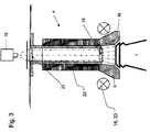
- a further embodiment of the hollow-wave packing tulip 4 shows FIG. 4 .
- the hollow-shaft packing tulip 4 has, as before, a hollow tulip holder 21, which, viewed in longitudinal section, has a cylindrical shape.
- an inner protective and guide tube 29 includes, which is flush with the tulip holder 21 feet.
- the inner protective and guide tube 29 is merely optional, and consists of a plastic, where against the tulip holder 21, as before, may be formed of a stainless steel. Of course, said material specifications are to be understood as exemplary only.
- the optional protective and guide tube 29 is surrounded on the outside by a light-guiding element 30.
- the light-guiding element 30 is embodied by way of example as a Plexiglas tube, but may also consist of a fiber bundle.
- the light-guiding element 30 extends from the head side of the packing tulip 4 in the direction of the opposite foot side, the light-guiding element 30 projecting beyond the lower edge of the tulip holder 21 and the optional protective and guide tube 29 with a projection 31.
- the light-guiding element 30 is surrounded on the outside by an outer protective tube 32. With the outer protective tube 32, the tulip bell 16 is in communication.
- the tulip bell 16 may be formed of a standard material, so does not need to be designed as a light guide.
- the light guide element 30 is assigned the light source 14, which in this exemplary embodiment is designed as ring light illumination 33.
- This ring light illumination may, for example, be formed as an LED ring of a plurality of individual LEDs.
- the ring light illumination 33 is embodied and arranged in such a way that emitted light is coupled into the light guide element 30 directly and completely uniformly on the head side.
- the light source 14, or the ring light illumination 33 can be constantly lit, but can also be in communication with the image processing and control unit 11, so as to appear or flash synchronously with the image recording of the optical system 11.
- the coupled light is directed towards the supernatant 31, where the light is coupled out, and the inner portion 23 of the tulip bell 16 lights.
- the optional protective and guide tube 29 or the tulip holder 21 with its cylindrical portion and / or the outer protective tube 32 may also be referred to as a covering element or cover for the light-guiding element 30, which seen light extraction from the light-guiding element 30 in the vertical direction before Supernatant 31 can avoid inward or outward.
- the light coupled in at the head ends at the projection 31 from the light-guiding element 30 inwards.
- the light is coupled out laterally obliquely by means of multiple reflections.
- the light-guiding element 30 may have a polished section at its overhang 31, so that virtually a prism 34 or a scattering prism 34 is formed so as to provide a homogeneous illumination of the inner region or a homogeneous illumination of the closure element 20 or its cover-side decoration to reach.
- the prism 34 may also be designed as a separate element, and be suitably fixed to the inner surface of the supernatant 31. It is also possible to occupy the inner surface of the supernatant 31 and the prism 34 with a diffuser material. Homogeneous illumination is particularly useful for reflective surfaces.
- FIG. 4 Lenses 27 and 28 as in the embodiment to FIG. 3 be provided.
- FIG. 5 shown variant of the device according to the invention provides a see-through cylinder 35, which is made of the same material as the cover view cuff 16 or other suitable transparent material.
- this see-through cylinder 35 has no concave or convex properties, but these can be provided by suitable cuts on the end faces to achieve advantageous lens effects.
- the ring light illumination 33 is designed or arranged in a multi-storey manner, so that emitted light is coupled directly into the see-through cylinder 35 directly and completely around the head.
- the ring light illumination 33 is electrically and control technology connected to lines not shown.
- the light source 14, or the ring light illumination 33 can be constantly lit, but can also be in communication with the image processing and control unit 11, so as to appear or flash synchronously with the image recording of the optical system 11.
- a lighting can be provided, similar to the in FIG. 2 shown example from the outside light into the tulip bell 16 and subsequently coupled into the see-through cylinder 35.
- the viewing cylinder 35 and subsequent illumination of the desired examination window e.g. a crown cap 20
- the advantage of the version according to FIG. 5 is that in the interior of the otherwise get Packtulpe 4 no contamination or deposits can take place.
- the possibility is offered, by means of at least one light source 14 in cooperation with the respective light guide 6 and 30 or with the erfindunsteren, at least partially photoconductive training of Packtulpe 4 and with the advantageous embodiment of the packing tulip 4 with photoconductive elements, the To illuminate closure element 20, or its cover-side decor, wherein by means of the camera 10, the image of the closure element 20, or its cover-side decor is imaged from above through the top plate 8 and through the packing tulip 4, to use the captured image for inspection purposes.
- the container 7 can be aligned according to lid features, whereby a quality control (lid seat) is feasible.
- the closure element 20 can also be converted into the desired position by means of the packing tulip or the tulip bell (capper).
- the Behelter solidaritysvorraum is not limited to the labeling machine described.
- the container treatment device can also be designed as a capper, in which the invention allows closure views through a plate opening from above through the packing tulip 4.
- the individual elements of the packing tulip 4, as these in the respective example of FIGS. 1 to 5 are shown appropriately combined, replaced or supplemented without thereby departing from the scope of the following claims.
Landscapes
- General Health & Medical Sciences (AREA)
- General Physics & Mathematics (AREA)
- Physics & Mathematics (AREA)
- Health & Medical Sciences (AREA)
- Life Sciences & Earth Sciences (AREA)
- Chemical & Material Sciences (AREA)
- Analytical Chemistry (AREA)
- Biochemistry (AREA)
- Pathology (AREA)
- Immunology (AREA)
- Engineering & Computer Science (AREA)
- Mechanical Engineering (AREA)
- Investigating Materials By The Use Of Optical Means Adapted For Particular Applications (AREA)
- Labeling Devices (AREA)
- Length Measuring Devices By Optical Means (AREA)
- Basic Packing Technique (AREA)
- Packaging Frangible Articles (AREA)
Claims (15)
- Dispositif de traitement de contenant, qui présente au moins un dispositif de centrage (2) pourvu d'une surface d'appui (3) et d'une tulipe de préhension (4), à savoir de telle manière que des contenants (7) peuvent être placés côté base sur la surface d'appui (3) concernée et peuvent être maintenus côté tête au moyen de la tulipe de préhension (4), sachant qu'est prévu au moins un système de détection et de commande (9), présentant au moins un système optique (10), sachant que la tulipe de préhension (4) présente aussi bien côté tête que côté base des ouvertures transparentes (19), caractérisé en ce
que la tulipe de préhension (4) présente un support de tulipe (21) creux, à travers lequel la trajectoire de rayons du système optique (10) mène,
et en ce qu'un élément conducteur de lumière (30) est disposé à l'intérieur de la tulipe de préhension, lequel s'étend depuis un côté de tête en direction d'un côté de base lui faisant face et qui comprend côté extérieur le support de tulipe, sachant que l'élément conducteur de lumière (30) dépasse par un débord (31) de l'arête inférieure du support de tulipe (21) et est entouré côté extérieur par un tube de protection (32) extérieur, et
en ce qu'au moins une source de lumière (14, 17 ; 14, 33) est prévue, laquelle est disposée de telle sorte que la lumière est injectée dans l'élément conducteur de lumière (30), sachant qu'une zone intérieure (23) d'une cloche de tulipe (16) de la tulipe de préhension (4) peut être éclairée par la lumière se découplant, de sorte qu'un côté de couvercle (24), pouvant être disposé au niveau de l'extrémité côté base de la tulipe de préhension (4), d'un contenant maintenu au moyen de la tulipe de préhension (4) peut être inspecté par le système optique (10), et à travers la tulipe de préhension (4) et au moyen de l'élément conducteur de lumière (30). - Dispositif de traitement de contenant selon la revendication 1, caractérisé en ce que le système optique (10) est disposé de manière stationnaire.
- Dispositif de traitement de contenant selon la revendication 1 ou 2, caractérisé en ce que la au moins une source de lumière (14, 17) est disposée de manière stationnaire.
- Dispositif de traitement de contenant selon l'une quelconque des revendications précédentes, caractérisé en ce que le côté de couvercle (24) ou la zone intérieure (23) éclairée peuvent être inspectés au moyen du système optique (10) à travers une ouverture de plaque (12) d'une plaque de tête (8) du dispositif de traitement de contenant (1) et à travers la tulipe de préhension (4).
- Dispositif de traitement de contenant selon l'une quelconque des revendications précédentes, caractérisé en ce que l'élément conducteur de lumière (30) est formé à partir d'un matériau transparent, en particulier d'une matière plastique transparente, de manière préférée à partir de plexiglas ou de macrolon.
- Dispositif de traitement de contenant selon l'une quelconque des revendications précédentes, caractérisé en ce que la source de lumière (14, 33) est disposée, en tant qu'éclairage circulaire (33), au niveau du côté de tête de l'élément conducteur de lumière (30).
- Dispositif de traitement de contenant selon l'une quelconque des revendications précédentes, caractérisé en ce que la lumière injectée au moyen de la source de lumière (14, 33) sort du débord (31) et éclaire la zone intérieure (23).
- Dispositif de traitement de contenant selon l'une quelconque des revendications précédentes, caractérisé en ce que la source de lumière (14, 17 ; 14, 33) et le système optique (10) sont commandés de manière synchronisée de telle sorte que le système optique (10) inspecte systématiquement une zone intérieure (23) éclairée.
- Dispositif de traitement de contenant selon l'une quelconque des revendications précédentes, caractérisé en ce que la source de lumière (14, 17 ; 14, 33) éclaire de manière constante, de sorte que l'élément conducteur de lumière (30) éclaire de manière constante la zone intérieure (23).
- Dispositif de traitement de contenant selon l'une quelconque des revendications précédentes, caractérisé en ce que sont prévues, côté tête et/ou côté base, dans la zone des ouvertures transparentes (19), des lentilles (27, 28) optiques.
- Dispositif de traitement de contenant selon la revendication 10, caractérisé en ce qu'est prévue, côté base, au moins une lentille (28), qui élargit les rayonnements, de sorte qu'une surface ombrée sous la lentille (28) peut être inspectée, dont le diamètre est plus grand que la section transversale libre devant la lentille (28).
- Dispositif de traitement de contenant selon l'une quelconque des revendications précédentes, caractérisé en ce que la partie centrale intérieure de la tulipe de préhension (4) est formée à partir d'un cylindre transparent (35), qui est formé à partir d'un matériau transparent, en particulier à partir d'une matière plastique transparente, de verre ou de cristal.
- Procédé servant à inspecter des bouteilles, des contenants ou un dispositif de traitement de contenant (1), caractérisé en ce qu'un dispositif de traitement de contenant selon l'une quelconque des revendications précédentes est utilisé, ledit procédé comprenant les étapes consistant à :a) placer un élément de fermeture (20) sur le récipient (7) dans une fermeuse :b) transporter ou transférer le contenant (7) à un dispositif à étiqueter (1) ;c) centrer le contenant (7) au moyen du dispositif de centrage (2), en particulier à la verticale sur la surface d'appui (3) et au moyen de la tulipe de préhension (4) maintenant le contenant ;d) inspecter le siège de couvercle au moyen du système optique (10) à travers la tulipe de préhension (4), sachant qu'une source de lumière est disposée de telle manière que la lumière est injectée dans les éléments conducteurs de lumière de la tulipe de préhension et est découplée dans une zone intérieure (23) d'une cloche de tulipe (16) de la tulipe de préhension (4) de sorte que la zone intérieure est éclairée ;e) orienter le contenant (7) selon une position de consigne requise.
- Procédé selon la revendication 13, caractérisé en ce qu'une orientation sommaire du contenant (7) est effectuée avant la mise en oeuvre de l'étape d) et/ou e).
- Procédé selon la revendication 13 ou 14, caractérisé eh ce qu'une ouverture de plaque (12) est pratiquée dans une plaque de tête (8) du dispositif de traitement de contenant (1), par laquelle le système optique (10) met en oeuvre l'inspection de siège de couvercle à travers la tulipe de préhension (4).
Applications Claiming Priority (2)
| Application Number | Priority Date | Filing Date | Title |
|---|---|---|---|
| DE102010012214A DE102010012214A1 (de) | 2010-03-19 | 2010-03-19 | Deckelsichttulpe |
| PCT/EP2010/007501 WO2011113463A1 (fr) | 2010-03-19 | 2010-12-09 | Tulipe de visibilité de couvercle |
Publications (2)
| Publication Number | Publication Date |
|---|---|
| EP2547591A1 EP2547591A1 (fr) | 2013-01-23 |
| EP2547591B1 true EP2547591B1 (fr) | 2016-03-23 |
Family
ID=43743487
Family Applications (1)
| Application Number | Title | Priority Date | Filing Date |
|---|---|---|---|
| EP10795228.5A Not-in-force EP2547591B1 (fr) | 2010-03-19 | 2010-12-09 | Tulipe de visibilité de couvercle |
Country Status (9)
| Country | Link |
|---|---|
| US (1) | US8804113B2 (fr) |
| EP (1) | EP2547591B1 (fr) |
| CN (1) | CN102781783B (fr) |
| BR (1) | BR112012021989A2 (fr) |
| DE (1) | DE102010012214A1 (fr) |
| ES (1) | ES2568525T3 (fr) |
| PL (1) | PL2547591T3 (fr) |
| RU (1) | RU2520040C1 (fr) |
| WO (1) | WO2011113463A1 (fr) |
Families Citing this family (14)
| Publication number | Priority date | Publication date | Assignee | Title |
|---|---|---|---|---|
| DE102008044926A1 (de) * | 2008-08-29 | 2010-03-25 | Khs Ag | Behälterausrichtung |
| JP6182722B2 (ja) * | 2013-07-17 | 2017-08-23 | キリンテクノシステム株式会社 | 容器の検査装置 |
| CN104555852A (zh) * | 2013-10-16 | 2015-04-29 | 山东工大机械有限公司 | 易拉罐封装自动落盖器 |
| EP2942321A1 (fr) * | 2014-05-05 | 2015-11-11 | Sidel S.p.a. Con Socio Unico | Usine d'embouteillage et ligne de convoyage de récipients |
| DE102014218363A1 (de) * | 2014-09-12 | 2016-03-17 | Krones Aktiengesellschaft | Vorrichtung und Verfahren zum Direktbedrucken und/oder Etikettieren von Behältern |
| DE102014218361A1 (de) * | 2014-09-12 | 2016-03-17 | Krones Ag | Vorrichtung und Verfahren zum Behandeln von Behältern durch Direktdruck und/oderEtikettierung |
| DE102014224519A1 (de) * | 2014-12-01 | 2016-06-02 | Krones Ag | Etikettiervorrichtung und -verfahren zur Etikettierung von Behältern |
| US10408766B2 (en) | 2015-02-04 | 2019-09-10 | Bosch Packaging Technology K.K. | Inspection device and inspection system |
| EP3085628A1 (fr) * | 2015-04-23 | 2016-10-26 | Sidel Participations, S.A.S. | Unité et procédé de fabrication d'articles remplis d'un produit versable |
| ITUA20162898A1 (it) * | 2016-04-26 | 2017-10-26 | Sacmi | Macchina etichettatrice di contenitori per liquidi con dispositivo di ispezione ottica |
| IT201700055395A1 (it) * | 2017-05-22 | 2018-11-22 | Telerobot S P A | Dispositivo di montaggio per oggetti plastici |
| CN108328542B (zh) * | 2018-02-05 | 2020-09-18 | 上海达和荣艺包装机械有限公司 | 一种高盖压盖机 |
| JP7392804B1 (ja) * | 2022-10-25 | 2023-12-06 | 株式会社アイシン | 穴検査用レンズユニット |
| CN116690523B (zh) * | 2023-08-04 | 2023-10-17 | 膳魔师(中国)家庭制品有限公司 | 自纠偏定向划线贴标装置及其划线贴标方法 |
Family Cites Families (21)
| Publication number | Priority date | Publication date | Assignee | Title |
|---|---|---|---|---|
| US3479514A (en) * | 1966-09-23 | 1969-11-18 | Anchor Hocking Corp | Method and means for inspecting glass articles |
| US3557950A (en) * | 1968-09-24 | 1971-01-26 | Powers Manufacturing | Photo-electric crack detector for glass bottles |
| US3944058A (en) * | 1973-04-19 | 1976-03-16 | Indian Head Inc. | Bottle conveyor system including adjustable height continuous belt conveyor and positive lock spray shielded rotatable bottle carrier |
| US4323158A (en) * | 1980-07-03 | 1982-04-06 | Wheaton Industries | Bottle neck finish inspection apparatus |
| DE3308489C2 (de) | 1983-03-10 | 1986-07-03 | Krones Ag Hermann Kronseder Maschinenfabrik, 8402 Neutraubling | Zentriervorrichtung für aufrecht stehende Gefäße, insbesondere in Etikettiermaschinen |
| US4915237A (en) * | 1986-09-11 | 1990-04-10 | Inex/Vistech Technologies, Inc. | Comprehensive container inspection system |
| JPS6480802A (en) * | 1987-09-24 | 1989-03-27 | Echo Kk | Bottle mouth inspecting device |
| JP2723983B2 (ja) * | 1989-07-14 | 1998-03-09 | サントリー株式会社 | キャップ締め角度検査装置 |
| JP2946613B2 (ja) | 1990-03-07 | 1999-09-06 | 澁谷工業株式会社 | 容器検査装置の光ガイド |
| US5398898A (en) * | 1993-11-01 | 1995-03-21 | Bever; Damon S. | Holding device |
| US5592286A (en) * | 1995-03-08 | 1997-01-07 | Alltrista Corporation | Container flange inspection system using an annular lens |
| JP3257356B2 (ja) | 1995-07-19 | 2002-02-18 | 富士通株式会社 | 気相成長装置及び気相成長方法並びに気相成長装置のクリーニング方法 |
| EP0873510B1 (fr) * | 1996-10-30 | 2006-02-01 | Krones Aktiengesellschaft | Dispositif d'inspection de bouteilles et autres articles similaires |
| JP2001080802A (ja) | 1999-09-16 | 2001-03-27 | Copyer Co Ltd | 画像形成装置 |
| JP2001221747A (ja) * | 2000-02-03 | 2001-08-17 | Suntory Ltd | 液体充填用容器の撮像方法および装置 |
| DE20115480U1 (de) | 2001-09-19 | 2002-05-16 | Heuft Systemtechnik Gmbh, 56659 Burgbrohl | Vorrichtung zum Anbringen von Etiketten an Behältern |
| DE202005006755U1 (de) * | 2005-04-26 | 2005-10-20 | Khs Maschinen- Und Anlagenbau Ag | Vorrichtung zur Verschlussausrichtung |
| DE102007025520A1 (de) | 2007-05-31 | 2008-12-04 | Khs Ag | Verfahren zum Ausrichten von Behältern sowie Vorrichtung zum Durchführen des Verfahrens |
| JP4813437B2 (ja) * | 2007-09-18 | 2011-11-09 | 株式会社日立情報制御ソリューションズ | 容器内の異物検出装置および異物検出方法 |
| DE102008044926A1 (de) * | 2008-08-29 | 2010-03-25 | Khs Ag | Behälterausrichtung |
| DE102009003649A1 (de) * | 2009-03-20 | 2010-09-23 | Krones Ag | Vorrichtung und Verfahren zur Behälterbehandlung |
-
2010
- 2010-03-19 DE DE102010012214A patent/DE102010012214A1/de not_active Withdrawn
- 2010-12-09 PL PL10795228.5T patent/PL2547591T3/pl unknown
- 2010-12-09 EP EP10795228.5A patent/EP2547591B1/fr not_active Not-in-force
- 2010-12-09 ES ES10795228.5T patent/ES2568525T3/es active Active
- 2010-12-09 BR BR112012021989-8A patent/BR112012021989A2/pt not_active Application Discontinuation
- 2010-12-09 CN CN201080065171.2A patent/CN102781783B/zh not_active Expired - Fee Related
- 2010-12-09 WO PCT/EP2010/007501 patent/WO2011113463A1/fr not_active Ceased
- 2010-12-09 US US13/580,467 patent/US8804113B2/en not_active Expired - Fee Related
- 2010-12-09 RU RU2012144404/12A patent/RU2520040C1/ru not_active IP Right Cessation
Also Published As
| Publication number | Publication date |
|---|---|
| US8804113B2 (en) | 2014-08-12 |
| PL2547591T3 (pl) | 2016-09-30 |
| RU2520040C1 (ru) | 2014-06-20 |
| WO2011113463A1 (fr) | 2011-09-22 |
| ES2568525T3 (es) | 2016-04-29 |
| DE102010012214A1 (de) | 2011-09-22 |
| US20120314213A1 (en) | 2012-12-13 |
| EP2547591A1 (fr) | 2013-01-23 |
| RU2012144404A (ru) | 2014-04-27 |
| CN102781783B (zh) | 2014-10-15 |
| CN102781783A (zh) | 2012-11-14 |
| BR112012021989A2 (pt) | 2020-09-01 |
Similar Documents
| Publication | Publication Date | Title |
|---|---|---|
| EP2547591B1 (fr) | Tulipe de visibilité de couvercle | |
| EP0873510B1 (fr) | Dispositif d'inspection de bouteilles et autres articles similaires | |
| EP3505918B1 (fr) | Procédé et dispositif de détection des bulles et / ou des plis sur des réservoirs étiquetés | |
| DE102014217771B4 (de) | Vorrichtung und Verfahren zur Qualitätskontrolle transparenter Objekte | |
| EP2379439B2 (fr) | Procédé ainsi que dispositif d'inspection pour vérifier des récipients | |
| DE102010012570B4 (de) | Vorrichtung und Verfahren zum Untersuchen von befüllten Behältnissen auf Fremdkörper | |
| EP2885630A1 (fr) | Inspection de l'intérieur de récipients par le bas à travers le fond | |
| EP2112502B1 (fr) | Procédé et dispositif de vérification de préformes de récipient | |
| EP2596340B1 (fr) | Système de détection pour l'orientation du joint de moule et des bossages de bouteilles et procédé pour le traitement de bouteilles. | |
| DE102014216576A1 (de) | Behälterbehandlungsmaschine mit einer Inspektionsvorrichtung | |
| DE102018130940A1 (de) | Vorrichtung und Verfahren zur Drehlageerkennung | |
| DE102007054657A1 (de) | Optische Erfassungseinrichtung, insbesondere zur Inspektion von Flaschen, sowie entsprechendes Visualisierungsverfahren | |
| EP2776817A1 (fr) | Contrôle et retour de récipients | |
| EP3980760A1 (fr) | Procédé et dispositif d'inspection optique de contenants | |
| EP3152550A1 (fr) | Dispositif d'inspection pour les fermetures de récipients | |
| DE102013103992A1 (de) | Testbehältnis zum Testen von Inspektionseinrichtungen | |
| EP3110701B1 (fr) | Dispositif d'inspection de recipients | |
| DE19920007C1 (de) | Vorrichtung zur Inspektion von Dichtflächen an Flaschen | |
| DE10146449A1 (de) | Verfahren zur Kontrolle von Verschlüssen auf Gefäßen | |
| DE102007036621A1 (de) | Verfahren und Vorrichtung zur Untersuchung von Flaschen aus Kunststoff oder Glas auf vorgewählte Eigenschaften | |
| DE102008015411A1 (de) | Transportsystem für Flaschen oder dergleichen Behälter sowie Vorrichtung zum Behandeln von Flaschen oder dergleichen Behältern | |
| EP2671649B1 (fr) | Dispositif d'identification d'une bouteille | |
| DE202012104043U1 (de) | Inspektionsvorrichtung für Behältnismündungen | |
| DE102007031749A1 (de) | Erkennungssystem für Markierungen im Schulter- und Halsbereich von Flaschen | |
| DE102009036389A1 (de) | Verfahren und Vorrichtung zur Überprüfung von mit Gefäßen bestückten oder bestückbaren, oben offenen Aufnahmebehältern |
Legal Events
| Date | Code | Title | Description |
|---|---|---|---|
| PUAI | Public reference made under article 153(3) epc to a published international application that has entered the european phase |
Free format text: ORIGINAL CODE: 0009012 |
|
| 17P | Request for examination filed |
Effective date: 20121019 |
|
| AK | Designated contracting states |
Kind code of ref document: A1 Designated state(s): AL AT BE BG CH CY CZ DE DK EE ES FI FR GB GR HR HU IE IS IT LI LT LU LV MC MK MT NL NO PL PT RO RS SE SI SK SM TR |
|
| DAX | Request for extension of the european patent (deleted) | ||
| 17Q | First examination report despatched |
Effective date: 20130710 |
|
| GRAP | Despatch of communication of intention to grant a patent |
Free format text: ORIGINAL CODE: EPIDOSNIGR1 |
|
| INTG | Intention to grant announced |
Effective date: 20151008 |
|
| GRAS | Grant fee paid |
Free format text: ORIGINAL CODE: EPIDOSNIGR3 |
|
| GRAA | (expected) grant |
Free format text: ORIGINAL CODE: 0009210 |
|
| AK | Designated contracting states |
Kind code of ref document: B1 Designated state(s): AL AT BE BG CH CY CZ DE DK EE ES FI FR GB GR HR HU IE IS IT LI LT LU LV MC MK MT NL NO PL PT RO RS SE SI SK SM TR |
|
| REG | Reference to a national code |
Ref country code: GB Ref legal event code: FG4D Free format text: NOT ENGLISH |
|
| REG | Reference to a national code |
Ref country code: CH Ref legal event code: EP |
|
| REG | Reference to a national code |
Ref country code: AT Ref legal event code: REF Ref document number: 782897 Country of ref document: AT Kind code of ref document: T Effective date: 20160415 |
|
| REG | Reference to a national code |
Ref country code: IE Ref legal event code: FG4D Free format text: LANGUAGE OF EP DOCUMENT: GERMAN |
|
| REG | Reference to a national code |
Ref country code: ES Ref legal event code: FG2A Ref document number: 2568525 Country of ref document: ES Kind code of ref document: T3 Effective date: 20160429 |
|
| REG | Reference to a national code |
Ref country code: DE Ref legal event code: R096 Ref document number: 502010011287 Country of ref document: DE |
|
| REG | Reference to a national code |
Ref country code: LT Ref legal event code: MG4D |
|
| REG | Reference to a national code |
Ref country code: NL Ref legal event code: MP Effective date: 20160323 |
|
| PG25 | Lapsed in a contracting state [announced via postgrant information from national office to epo] |
Ref country code: GR Free format text: LAPSE BECAUSE OF FAILURE TO SUBMIT A TRANSLATION OF THE DESCRIPTION OR TO PAY THE FEE WITHIN THE PRESCRIBED TIME-LIMIT Effective date: 20160624 Ref country code: NO Free format text: LAPSE BECAUSE OF FAILURE TO SUBMIT A TRANSLATION OF THE DESCRIPTION OR TO PAY THE FEE WITHIN THE PRESCRIBED TIME-LIMIT Effective date: 20160623 Ref country code: FI Free format text: LAPSE BECAUSE OF FAILURE TO SUBMIT A TRANSLATION OF THE DESCRIPTION OR TO PAY THE FEE WITHIN THE PRESCRIBED TIME-LIMIT Effective date: 20160323 Ref country code: HR Free format text: LAPSE BECAUSE OF FAILURE TO SUBMIT A TRANSLATION OF THE DESCRIPTION OR TO PAY THE FEE WITHIN THE PRESCRIBED TIME-LIMIT Effective date: 20160323 |
|
| PG25 | Lapsed in a contracting state [announced via postgrant information from national office to epo] |
Ref country code: RS Free format text: LAPSE BECAUSE OF FAILURE TO SUBMIT A TRANSLATION OF THE DESCRIPTION OR TO PAY THE FEE WITHIN THE PRESCRIBED TIME-LIMIT Effective date: 20160323 Ref country code: LT Free format text: LAPSE BECAUSE OF FAILURE TO SUBMIT A TRANSLATION OF THE DESCRIPTION OR TO PAY THE FEE WITHIN THE PRESCRIBED TIME-LIMIT Effective date: 20160323 Ref country code: LV Free format text: LAPSE BECAUSE OF FAILURE TO SUBMIT A TRANSLATION OF THE DESCRIPTION OR TO PAY THE FEE WITHIN THE PRESCRIBED TIME-LIMIT Effective date: 20160323 Ref country code: SE Free format text: LAPSE BECAUSE OF FAILURE TO SUBMIT A TRANSLATION OF THE DESCRIPTION OR TO PAY THE FEE WITHIN THE PRESCRIBED TIME-LIMIT Effective date: 20160323 Ref country code: NL Free format text: LAPSE BECAUSE OF FAILURE TO SUBMIT A TRANSLATION OF THE DESCRIPTION OR TO PAY THE FEE WITHIN THE PRESCRIBED TIME-LIMIT Effective date: 20160323 |
|
| PG25 | Lapsed in a contracting state [announced via postgrant information from national office to epo] |
Ref country code: IS Free format text: LAPSE BECAUSE OF FAILURE TO SUBMIT A TRANSLATION OF THE DESCRIPTION OR TO PAY THE FEE WITHIN THE PRESCRIBED TIME-LIMIT Effective date: 20160723 Ref country code: EE Free format text: LAPSE BECAUSE OF FAILURE TO SUBMIT A TRANSLATION OF THE DESCRIPTION OR TO PAY THE FEE WITHIN THE PRESCRIBED TIME-LIMIT Effective date: 20160323 |
|
| PG25 | Lapsed in a contracting state [announced via postgrant information from national office to epo] |
Ref country code: PT Free format text: LAPSE BECAUSE OF FAILURE TO SUBMIT A TRANSLATION OF THE DESCRIPTION OR TO PAY THE FEE WITHIN THE PRESCRIBED TIME-LIMIT Effective date: 20160725 Ref country code: RO Free format text: LAPSE BECAUSE OF FAILURE TO SUBMIT A TRANSLATION OF THE DESCRIPTION OR TO PAY THE FEE WITHIN THE PRESCRIBED TIME-LIMIT Effective date: 20160323 Ref country code: SM Free format text: LAPSE BECAUSE OF FAILURE TO SUBMIT A TRANSLATION OF THE DESCRIPTION OR TO PAY THE FEE WITHIN THE PRESCRIBED TIME-LIMIT Effective date: 20160323 Ref country code: SK Free format text: LAPSE BECAUSE OF FAILURE TO SUBMIT A TRANSLATION OF THE DESCRIPTION OR TO PAY THE FEE WITHIN THE PRESCRIBED TIME-LIMIT Effective date: 20160323 Ref country code: CZ Free format text: LAPSE BECAUSE OF FAILURE TO SUBMIT A TRANSLATION OF THE DESCRIPTION OR TO PAY THE FEE WITHIN THE PRESCRIBED TIME-LIMIT Effective date: 20160323 |
|
| REG | Reference to a national code |
Ref country code: FR Ref legal event code: PLFP Year of fee payment: 7 |
|
| REG | Reference to a national code |
Ref country code: DE Ref legal event code: R097 Ref document number: 502010011287 Country of ref document: DE |
|
| PLBE | No opposition filed within time limit |
Free format text: ORIGINAL CODE: 0009261 |
|
| STAA | Information on the status of an ep patent application or granted ep patent |
Free format text: STATUS: NO OPPOSITION FILED WITHIN TIME LIMIT |
|
| PG25 | Lapsed in a contracting state [announced via postgrant information from national office to epo] |
Ref country code: DK Free format text: LAPSE BECAUSE OF FAILURE TO SUBMIT A TRANSLATION OF THE DESCRIPTION OR TO PAY THE FEE WITHIN THE PRESCRIBED TIME-LIMIT Effective date: 20160323 |
|
| PG25 | Lapsed in a contracting state [announced via postgrant information from national office to epo] |
Ref country code: BG Free format text: LAPSE BECAUSE OF FAILURE TO SUBMIT A TRANSLATION OF THE DESCRIPTION OR TO PAY THE FEE WITHIN THE PRESCRIBED TIME-LIMIT Effective date: 20160623 |
|
| 26N | No opposition filed |
Effective date: 20170102 |
|
| PG25 | Lapsed in a contracting state [announced via postgrant information from national office to epo] |
Ref country code: BE Free format text: LAPSE BECAUSE OF NON-PAYMENT OF DUE FEES Effective date: 20161231 Ref country code: SI Free format text: LAPSE BECAUSE OF FAILURE TO SUBMIT A TRANSLATION OF THE DESCRIPTION OR TO PAY THE FEE WITHIN THE PRESCRIBED TIME-LIMIT Effective date: 20160323 |
|
| REG | Reference to a national code |
Ref country code: CH Ref legal event code: PL |
|
| PG25 | Lapsed in a contracting state [announced via postgrant information from national office to epo] |
Ref country code: MC Free format text: LAPSE BECAUSE OF FAILURE TO SUBMIT A TRANSLATION OF THE DESCRIPTION OR TO PAY THE FEE WITHIN THE PRESCRIBED TIME-LIMIT Effective date: 20160323 |
|
| REG | Reference to a national code |
Ref country code: IE Ref legal event code: MM4A |
|
| PG25 | Lapsed in a contracting state [announced via postgrant information from national office to epo] |
Ref country code: LI Free format text: LAPSE BECAUSE OF NON-PAYMENT OF DUE FEES Effective date: 20161231 Ref country code: LU Free format text: LAPSE BECAUSE OF NON-PAYMENT OF DUE FEES Effective date: 20161209 Ref country code: CH Free format text: LAPSE BECAUSE OF NON-PAYMENT OF DUE FEES Effective date: 20161231 |
|
| PG25 | Lapsed in a contracting state [announced via postgrant information from national office to epo] |
Ref country code: IE Free format text: LAPSE BECAUSE OF NON-PAYMENT OF DUE FEES Effective date: 20161209 |
|
| REG | Reference to a national code |
Ref country code: FR Ref legal event code: PLFP Year of fee payment: 8 |
|
| PGFP | Annual fee paid to national office [announced via postgrant information from national office to epo] |
Ref country code: FR Payment date: 20171221 Year of fee payment: 8 Ref country code: DE Payment date: 20171211 Year of fee payment: 8 |
|
| REG | Reference to a national code |
Ref country code: BE Ref legal event code: MM Effective date: 20161231 |
|
| PGFP | Annual fee paid to national office [announced via postgrant information from national office to epo] |
Ref country code: GB Payment date: 20171221 Year of fee payment: 8 Ref country code: PL Payment date: 20171123 Year of fee payment: 8 Ref country code: AT Payment date: 20171221 Year of fee payment: 8 |
|
| PGFP | Annual fee paid to national office [announced via postgrant information from national office to epo] |
Ref country code: ES Payment date: 20180124 Year of fee payment: 8 |
|
| PG25 | Lapsed in a contracting state [announced via postgrant information from national office to epo] |
Ref country code: HU Free format text: LAPSE BECAUSE OF FAILURE TO SUBMIT A TRANSLATION OF THE DESCRIPTION OR TO PAY THE FEE WITHIN THE PRESCRIBED TIME-LIMIT; INVALID AB INITIO Effective date: 20101209 Ref country code: CY Free format text: LAPSE BECAUSE OF FAILURE TO SUBMIT A TRANSLATION OF THE DESCRIPTION OR TO PAY THE FEE WITHIN THE PRESCRIBED TIME-LIMIT Effective date: 20160323 |
|
| PGFP | Annual fee paid to national office [announced via postgrant information from national office to epo] |
Ref country code: IT Payment date: 20171221 Year of fee payment: 8 |
|
| PG25 | Lapsed in a contracting state [announced via postgrant information from national office to epo] |
Ref country code: MK Free format text: LAPSE BECAUSE OF FAILURE TO SUBMIT A TRANSLATION OF THE DESCRIPTION OR TO PAY THE FEE WITHIN THE PRESCRIBED TIME-LIMIT Effective date: 20160323 Ref country code: TR Free format text: LAPSE BECAUSE OF FAILURE TO SUBMIT A TRANSLATION OF THE DESCRIPTION OR TO PAY THE FEE WITHIN THE PRESCRIBED TIME-LIMIT Effective date: 20160323 |
|
| PG25 | Lapsed in a contracting state [announced via postgrant information from national office to epo] |
Ref country code: MT Free format text: LAPSE BECAUSE OF FAILURE TO SUBMIT A TRANSLATION OF THE DESCRIPTION OR TO PAY THE FEE WITHIN THE PRESCRIBED TIME-LIMIT Effective date: 20160323 |
|
| PG25 | Lapsed in a contracting state [announced via postgrant information from national office to epo] |
Ref country code: AL Free format text: LAPSE BECAUSE OF FAILURE TO SUBMIT A TRANSLATION OF THE DESCRIPTION OR TO PAY THE FEE WITHIN THE PRESCRIBED TIME-LIMIT Effective date: 20160323 |
|
| REG | Reference to a national code |
Ref country code: DE Ref legal event code: R119 Ref document number: 502010011287 Country of ref document: DE |
|
| REG | Reference to a national code |
Ref country code: AT Ref legal event code: MM01 Ref document number: 782897 Country of ref document: AT Kind code of ref document: T Effective date: 20181209 |
|
| GBPC | Gb: european patent ceased through non-payment of renewal fee |
Effective date: 20181209 |
|
| PG25 | Lapsed in a contracting state [announced via postgrant information from national office to epo] |
Ref country code: IT Free format text: LAPSE BECAUSE OF NON-PAYMENT OF DUE FEES Effective date: 20181209 Ref country code: DE Free format text: LAPSE BECAUSE OF NON-PAYMENT OF DUE FEES Effective date: 20190702 Ref country code: FR Free format text: LAPSE BECAUSE OF NON-PAYMENT OF DUE FEES Effective date: 20181231 |
|
| PG25 | Lapsed in a contracting state [announced via postgrant information from national office to epo] |
Ref country code: GB Free format text: LAPSE BECAUSE OF NON-PAYMENT OF DUE FEES Effective date: 20181209 Ref country code: AT Free format text: LAPSE BECAUSE OF NON-PAYMENT OF DUE FEES Effective date: 20181209 |
|
| REG | Reference to a national code |
Ref country code: ES Ref legal event code: FD2A Effective date: 20200131 |
|
| PG25 | Lapsed in a contracting state [announced via postgrant information from national office to epo] |
Ref country code: ES Free format text: LAPSE BECAUSE OF NON-PAYMENT OF DUE FEES Effective date: 20181210 |
|
| PG25 | Lapsed in a contracting state [announced via postgrant information from national office to epo] |
Ref country code: PL Free format text: LAPSE BECAUSE OF NON-PAYMENT OF DUE FEES Effective date: 20181209 |