EP2547893B1 - Ermittlung von lüfterparametern durch drucküberwachung - Google Patents
Ermittlung von lüfterparametern durch drucküberwachung Download PDFInfo
- Publication number
- EP2547893B1 EP2547893B1 EP11790135.5A EP11790135A EP2547893B1 EP 2547893 B1 EP2547893 B1 EP 2547893B1 EP 11790135 A EP11790135 A EP 11790135A EP 2547893 B1 EP2547893 B1 EP 2547893B1
- Authority
- EP
- European Patent Office
- Prior art keywords
- sensor
- propeller
- blades
- fan
- pressure
- Prior art date
- Legal status (The legal status is an assumption and is not a legal conclusion. Google has not performed a legal analysis and makes no representation as to the accuracy of the status listed.)
- Active
Links
Images


Classifications
-
- F—MECHANICAL ENGINEERING; LIGHTING; HEATING; WEAPONS; BLASTING
- F02—COMBUSTION ENGINES; HOT-GAS OR COMBUSTION-PRODUCT ENGINE PLANTS
- F02K—JET-PROPULSION PLANTS
- F02K3/00—Plants including a gas turbine driving a compressor or a ducted fan
- F02K3/02—Plants including a gas turbine driving a compressor or a ducted fan in which part of the working fluid by-passes the turbine and combustion chamber
- F02K3/04—Plants including a gas turbine driving a compressor or a ducted fan in which part of the working fluid by-passes the turbine and combustion chamber the plant including ducted fans, i.e. fans with high volume, low pressure outputs, for augmenting the jet thrust, e.g. of double-flow type
- F02K3/06—Plants including a gas turbine driving a compressor or a ducted fan in which part of the working fluid by-passes the turbine and combustion chamber the plant including ducted fans, i.e. fans with high volume, low pressure outputs, for augmenting the jet thrust, e.g. of double-flow type with front fan
-
- F—MECHANICAL ENGINEERING; LIGHTING; HEATING; WEAPONS; BLASTING
- F01—MACHINES OR ENGINES IN GENERAL; ENGINE PLANTS IN GENERAL; STEAM ENGINES
- F01D—NON-POSITIVE DISPLACEMENT MACHINES OR ENGINES, e.g. STEAM TURBINES
- F01D21/00—Shutting-down of machines or engines, e.g. in emergency; Regulating, controlling, or safety means not otherwise provided for
- F01D21/003—Arrangements for testing or measuring
-
- F—MECHANICAL ENGINEERING; LIGHTING; HEATING; WEAPONS; BLASTING
- F02—COMBUSTION ENGINES; HOT-GAS OR COMBUSTION-PRODUCT ENGINE PLANTS
- F02C—GAS-TURBINE PLANTS; AIR INTAKES FOR JET-PROPULSION PLANTS; CONTROLLING FUEL SUPPLY IN AIR-BREATHING JET-PROPULSION PLANTS
- F02C9/00—Controlling gas-turbine plants; Controlling fuel supply in air- breathing jet-propulsion plants
- F02C9/26—Control of fuel supply
- F02C9/28—Regulating systems responsive to plant or ambient parameters, e.g. temperature, pressure, rotor speed
-
- F—MECHANICAL ENGINEERING; LIGHTING; HEATING; WEAPONS; BLASTING
- F02—COMBUSTION ENGINES; HOT-GAS OR COMBUSTION-PRODUCT ENGINE PLANTS
- F02K—JET-PROPULSION PLANTS
- F02K3/00—Plants including a gas turbine driving a compressor or a ducted fan
- F02K3/02—Plants including a gas turbine driving a compressor or a ducted fan in which part of the working fluid by-passes the turbine and combustion chamber
- F02K3/04—Plants including a gas turbine driving a compressor or a ducted fan in which part of the working fluid by-passes the turbine and combustion chamber the plant including ducted fans, i.e. fans with high volume, low pressure outputs, for augmenting the jet thrust, e.g. of double-flow type
- F02K3/072—Plants including a gas turbine driving a compressor or a ducted fan in which part of the working fluid by-passes the turbine and combustion chamber the plant including ducted fans, i.e. fans with high volume, low pressure outputs, for augmenting the jet thrust, e.g. of double-flow type with counter-rotating, e.g. fan rotors
-
- G—PHYSICS
- G01—MEASURING; TESTING
- G01P—MEASURING LINEAR OR ANGULAR SPEED, ACCELERATION, DECELERATION, OR SHOCK; INDICATING PRESENCE, ABSENCE, OR DIRECTION, OF MOVEMENT
- G01P3/00—Measuring linear or angular speed; Measuring differences of linear or angular speeds
- G01P3/26—Devices characterised by the use of fluids
- G01P3/263—Devices characterised by the use of fluids by using fluidic impulse generators
-
- G—PHYSICS
- G01—MEASURING; TESTING
- G01P—MEASURING LINEAR OR ANGULAR SPEED, ACCELERATION, DECELERATION, OR SHOCK; INDICATING PRESENCE, ABSENCE, OR DIRECTION, OF MOVEMENT
- G01P3/00—Measuring linear or angular speed; Measuring differences of linear or angular speeds
- G01P3/42—Devices characterised by the use of electric or magnetic means
- G01P3/44—Devices characterised by the use of electric or magnetic means for measuring angular speed
- G01P3/48—Devices characterised by the use of electric or magnetic means for measuring angular speed by measuring frequency of generated current or voltage
-
- F—MECHANICAL ENGINEERING; LIGHTING; HEATING; WEAPONS; BLASTING
- F05—INDEXING SCHEMES RELATING TO ENGINES OR PUMPS IN VARIOUS SUBCLASSES OF CLASSES F01-F04
- F05D—INDEXING SCHEME FOR ASPECTS RELATING TO NON-POSITIVE-DISPLACEMENT MACHINES OR ENGINES, GAS-TURBINES OR JET-PROPULSION PLANTS
- F05D2260/00—Function
- F05D2260/80—Diagnostics
-
- F—MECHANICAL ENGINEERING; LIGHTING; HEATING; WEAPONS; BLASTING
- F05—INDEXING SCHEMES RELATING TO ENGINES OR PUMPS IN VARIOUS SUBCLASSES OF CLASSES F01-F04
- F05D—INDEXING SCHEME FOR ASPECTS RELATING TO NON-POSITIVE-DISPLACEMENT MACHINES OR ENGINES, GAS-TURBINES OR JET-PROPULSION PLANTS
- F05D2270/00—Control
- F05D2270/30—Control parameters, e.g. input parameters
- F05D2270/301—Pressure
Definitions
- the invention relates to monitoring the parameters of a fan, such as the speed of rotation.
- U.S. Pat. No. 6,918,747 discloses a method and system for detecting damage to the rotor of an aircraft engine using devices for measuring vibration and speed in order to acquire data relating to the speed of the rotor and also to the amplitude and the phase of rotor vibration during a determined flight.
- the method includes the following steps: reading the acquired data; calculating a mean vibration vector over a determined rotor speed range on the basis of the acquired data; calculating a vector difference between the mean vibration vector of the determined flight and the mean vibration vector of a reference flight for the rotor speed range; comparing the modulus of the vector difference with a predetermined threshold value; and issuing a warning signal when the modulus of the vector difference exceeds the predetermined threshold value, the steps being performed after the determined flight has been completed.
- Document WO 2006/059976 A1 describes a fan-turbine rotor assembly mounted for rotation about an engine centerline aft of an axial compressor, wherein the fan-turbine rotor assembly includes a plurality of hollow fan blades to provide internal, centrifugal compression of the compressed airflow from the axial compressor for distribution to an annular combustor located within a rotationally fixed static outer support structure.
- a rate sensor in the form of an electromagnetic proximity sensor is mounted adjacent the fan-turbine rotor assembly, and detects the proximity of a ferromagnetic portion of the fan-turbine rotor assembly as it passes the rate sensor upon each rotation.
- the rate of rotation of the fan-turbine rotor assembly is determined, wherein the calculated rate is sent to a data processor controlling the engine based upon the rate of rotation of the fan-turbine rotor assembly.
- Document US 7 445 431 B2 describes a method for controlling the aerodynamic load of a wind turbine's blades individually in such a way that the dynamic aerodynamic loads on the turbine are reduced and power production is optimized.
- Document US 2005/0276696 A1 discloses a method for detecting ice on a wind turbine rotor
- document US 2006/0119348 A1 describes a technique for sensing the rotational speed and angular position of a rotating wheel using a variable threshold
- document US 5 463 458 A discloses a Mach number sensor
- document US 2009/0263247 A1 describes the monitoring of vibration in a dual rotor engine.
- the current invention is a method according to claim 4 for determining the speed of at least one rotating fan, such as a propeller, through sensing pressure waves generated by the blades of the fan.
- the current invention is also an apparatus according to claim 1 operable to execute the method.
- the apparatus includes a fan having a hub portion and a plurality of blades extending radially outward from the hub portion.
- the apparatus also includes an engine operable to rotate the fan about an axis of rotation.
- the apparatus also includes a sensor spaced from the fan along the axis of rotation.
- the sensor is positioned to sense at least one physical condition that is external of the engine and is changed by rotation of the plurality of blades.
- the sensor is operable to emit a signal corresponding to at least one physical condition.
- the apparatus also includes a processor operably engaged with the engine and the sensor.
- the processor is operable to receive the signal from the sensor and change the operation of the engine in response to the signal to change a speed of the fan.
- the invention can be applied to determine the parameters of a fan.
- the parameters of a fan can include speed of rotation, blade pitch, vibration of the fan, or imbalance in the fan.
- a propeller is an example of a fan.
- direct physical measurement of propeller speed is challenging.
- two adjacent propellers are disposed to rotate in opposite directions relative to one another. Measurement of the rotor or drive shaft causing rotation of the propellers may not be appropriate if there is no direct correlation between the rotational speed of the drive shaft and the rotational speed of the propellers. Also, the two propellers do not have a correlated speed since they turn in opposite directions.
- the exemplary embodiment can be applied to indirectly assess propeller speed as well as other parameters.
- FIG. 1 is a schematic representation of a turbine engine incorporating first exemplary embodiment of the invention.
- a turbine engine 10 can include an inlet 12 and be housed in a nacelle 14.
- the turbine engine 10 can also include a compressor section 16, a combustor section 18, and a turbine section 20.
- the turbine engine 10 can also include an exhaust section 22.
- the compressor section 16, combustor section 18, turbine section 20, and exhaust section 22 can be arranged along a centerline axis 24. Components of the compressor section 16 and the turbine section 20 can rotate about the centerline axis 24.
- Fluid such as air can be drawn into the turbine engine 10 as indicated by the arrows referenced at 26. The fluid enters the compressor section 16 from the inlet 12 and is compressed.
- a nose cone 28 can be proximate to the inlet 12 to gently direct air into the compressor section 16.
- the schematically shown compressor section 16 includes high and low pressure compressor sections. In some embodiments, a portion of the fluid can be diverted radially outside of the compressor section 16 and thereby become bypass flow.
- the compressed fluid emerging from the compressor section 16 is mixed with fuel from a fuel system 30 and ignited in the combustor section 18. Combustion gases exit the combustor section 18 and flow through the turbine section 20. Energy is extracted from the combustion gases in the turbine section 20.
- a turbine case 32 can encircle the core engine components (the compressor, combustor and turbine sections 16, 18, 20).
- the case 32 can support nonrotating structures such as compressor vanes (not shown) and turbine vanes.
- Exemplary turbine vanes are referenced at 34 and 36 and can be positioned to direct the flow of combustion gases to the turbine section 20.
- the combustion gases passing aft of the turbine section are referenced by unnumbered arrows. These gases can be applied to generate thrust for an aircraft.
- power can be drawn from the core engine components to rotate propellers 38, 40.
- Each of the propellers respectively includes a hub portion 42, 44 and a plurality of blades, such as blades 46, 48.
- one or more free power turbines, such as turbines 50, 52 can drive a shaft 54. Combustion gases pass over and thereby cause rotation of the free power turbines 50, 52.
- the shaft 54 can extend into a gear box 56. Respective drive shafts 58, 60 can extend from the gear box 56.
- the drive shaft 58 is fixed for rotation with the hub portion 42 of the propeller 38.
- the drive shaft 60 is fixed for rotation with the hub portion 44 of the propeller 40.
- the gears (not shown) of the gear box 54 can transmit the power input by the shaft 54 into counter-rotation of the propellers 38 and 40.
- the schematic illustration of Figure 1 is a "pusher" open rotor configuration and it is noted that embodiments of the invention can be practiced with “tractor” open rotor configuration wherein the propellers are forward/upstream of the compressor section.
- Figure 1 also shows a sensor 62 spaced from the propellers 38, 40 along the axis 24 of rotation.
- the sensor 62 is positioned to sense at least one physical condition that is external of the turbine engine 10 and is changed by rotation of the plurality of blades 46 and/or 48.
- the sensor 62 can sense at least one physical condition changed by rotation of both of the plurality of blades of the propellers 38 and 40.
- a sensor can be positioned to sense at least one physical condition changed by rotation of the single fan.
- other embodiments of the invention can be practiced wherein a sensor can be positioned to sense at least one physical condition that is changed by rotation of a single fan of two adjacent fans.
- the sensor 62 can be positioned upstream or downstream of the propellers 38, 40.
- the sensor 62 can be flush with the nacelle 14 such that part of the sensor 62 that is substantially synchronous with the outer surface 94 of the nacelle 14.
- the portion of the sensor 62 that is aligned with the outer surface of the nacelle 14 does not substantially disrupt laminar flow over the nacelle 14.
- the sensor 62 will sense the physical condition in a field of view.
- the field of view of the sensor 62 can be centered along an axis that does not intersect the blades.
- the exemplary sensor 62 can have a field of view centered on an axis 64 extending perpendicular to the axis 24.
- the sensor 62 can be positioned such that the field of view is centered on an axis that is oblique or parallel to the axis 24.
- a sensor is a device that measures a physical quantity and converts it into a signal which can be read by an observer or by an instrument such as processor.
- the exemplary sensor 62 can be operable to sense a level of ambient pressure. In alternative embodiments, a sensor can be operable to sense a level of sound.
- the rotation of the propellers 38, 40 can cause changes in the ambient pressure and can also generate sound waves.
- Sound waves are pressure oscillations.
- the sound pressure is the difference between the pressure wave of sound and the average ambient pressure of the medium outside of the sound wave in which the sound wave is traveling. Embodiments of the invention can be practiced in which ambient pressure is sensed and/or in which the sound pressure is sensed.
- the sensor 62 can be a pressure sensor 62, operable to sense the level of ambient pressure.
- a pressure sensor 62 can generate a signal as a function of the pressure imposed on the sensor's field of view.
- the signal can be electrical.
- Pressure sensors can alternatively be called pressure transducers, pressure transmitters, pressure senders, pressure indicators, piezometers, and manometers, for example.
- pressure sensors can be an absolute pressure sensor, a gauge pressure sensor, a vacuum pressure sensor, a differential pressure sensor, a sealed pressure sensor, for example.
- Pressure sensors can sense pressure through force collection, such as with a piezoresistive strain gage, capacitive methods, electromagnetic methods, piezoelectric structures, optical fibers, potentiometric technology. It is noted that any kind of pressure sensor can be applied in embodiments of the invention.
- a pressure sensor applied in an embodiment of the invention can be selected in view of the operating conditions associated with the embodiment.
- Sound pressure is the local pressure deviation from the ambient (average or equilibrium) pressure caused by a sound wave.
- a sensor for detecting sound is, in general, called a microphone.
- the microphone can be classified into several basic types including dynamic, electrostatic, and piezoelectric, for example.
- Conventional microphones can measure sound pressure, which represents sound intensity at a specific place. Sound intensity is a measure of the flow of energy passing through a unit area per unit time.
- a sound intensity microphone probe can capture sound intensity together with the unit direction of flow as a vector quantity. It is noted that any kind of sound sensor can be applied in embodiments of the invention.
- a sound sensor applied in an embodiment of the invention can be selected in view of the operating conditions associated with the embodiment.
- embodiments of the invention can be practiced with a sensor operable to sense vibration.
- the variation in pressure around a propeller, whether in terms of ambient pressure or because of sound waves could be sensed by allowing a mass to vibrate in the field of pressure changes.
- the exemplary sensor 62 is operable to emit a signal corresponding to the ambient pressure.
- the signal can be a continuous and analyzed in real time.
- Figure 2 is an exemplary graph showing data emitted by the sensor 62 in the time domain. The x-axis of the graph corresponds to time and the y-axis of the graph corresponds to the magnitude of pressure. It is noted that the graph of Figure 2 reflects changes in ambient pressure caused by the closest propeller 38 as well as the furthest propeller 40.
- the sensor 62 is thus positioned to concurrently sense at least one physical condition external of the engine changed by rotation of the plurality of blades of the first propeller 38 and changed by rotation of the plurality of blades of the second propeller 40.
- a processor 66 is operably engaged with the turbine engine 10 and the sensor 62.
- the processor 66 is operable to receive the signal from the sensor 62 and change the operation of the turbine engine 10 in response to the signal.
- the processor 66 can control the fuel system 30 to direct more or less fuel to the combustor section 18 in response to the signal received from the sensor 62. More or less fuel can be directed to increase or decrease, respectively, the speed of the propellers.
- the sensor 62 can sense the pressure dynamically (continuously over time).
- the sensed variation in pressure over time can be represented as a graph in the time domain, such as shown in Figure 2 .
- the processor 66 can be operable to convert the pressure data sensed in the time domain to the frequency domain with a fast Fourier transform.
- a fast Fourier transform is an algorithm to compute the discrete Fourier transform (DFT) and its inverse.
- DFT discrete Fourier transform
- a DFT decomposes a sequence of values into components of different frequencies.
- An FFT is a way to compute the same result as a DFT, but more quickly.
- an FFT can be programmed into the processor 66.
- Embodiments of the invention can apply any FFT algorithm.
- Figure 3 shows the resulting graph when the signal corresponding to the sensed variation in ambient pressure is converted from the time domain ( Figure 2 ) to the frequency domain with an FFT.
- the x-axis of the graph of Figure 3 corresponds to frequency and the y-axis of the graph corresponds to magnitude, a non-dimensional and absolute value being less than one.
- the exemplary graph of the frequency domain reveals two dominant frequencies, substantially 125 Hz and 128 Hz. These two dominant frequencies have the highest magnitude in the frequency domain and can be associated the angular velocities of the respective propellers 38, 40 (shown in Figure 1 ). The other frequencies can be dismissed as noise.
- the higher magnitude frequency (in the exemplary embodiment, 128 Hz) can be associated with the propeller 38 nearest to the sensor 62 since the magnitude of ambient pressure changes caused by the nearest propeller 38 will be greater than the magnitude of ambient pressure changes caused by the furthest propeller 38.
- the magnitude is defined along the y-axis and not along the axis.
- a point referenced at 88 corresponds to the highest magnitude of any frequency identified along the x-axis.
- the rotational speeds (angular velocities) of the respective propellers 38, 40 can be determined by dividing each respective frequency by the number of blades of the respective propeller 38, 40. In the exemplary embodiment, if the propeller 38 has five blades, the speed of rotation of the propeller 38 would be around 25.6 revolutions per second. It is noted that the values provided in the graphs of Figures 2 and 3 are exemplary and not applicable to every embodiment of the invention.
- Figure 4 is a second graph of data in the time domain that can be associated with the exemplary turbine engine shown in Figure 1 .
- the graph in Figure 2 shows the effect of noise in the display of pressure data
- the graph in Figure 4 can be acquired by filtering substantially all noise from the signal received from the sensor 62 (shown in Figure 1 ). Filtering is not absolutely necessary but can be desirable to simplify processing.
- the cumulative wave form includes a series of relatively high amplitude peaks in alternating relationship with a series of relatively low amplitude peaks.
- Each of the series of relatively high amplitude peaks corresponds to a blade from the nearest propeller passing by the sensor.
- Each of the series of relatively low amplitude peaks corresponds to a blade from the furthest propeller passing by the sensor.
- Figure 4 reflects two propellers rotating at the same speed and 180° out of phase from one another. Thus, Figure 4 does not correspond to Figure 3 wherein the propellers are rotating at different speeds. Embodiments of the invention can be practiced wherein two propel lers are not rotating at the same speed and/or are out of phase from one another some angle different from 180°.
- the wave form in the time domain includes an individual peaks characterized by a "rise + decay" time (RD time) and an amplitude.
- the RD time of the first individual peak extends between the points referenced at 68 and 70.
- the amplitude of the first individual peak corresponds to the maximum pressure reached during this portion of the wave and is referenced at point 72.
- the rise portion of the RD time extending between the point 68 and a point referenced at point 74, can be shorter than the decay portion of the RD time.
- the decay portion of the first peak extends between the points 74 and 72.
- the line passing through points 68, 74, and 70 can be perfectly parallel to the x-axis or substantially parallel.
- the data acquired in the time domain can be processed to ascertain a pitch of the blades of the propellers,
- the blade 46 is travelling past the sensor 62 along an axis 75.
- the axis 75 corresponds to the path of rotational movement for the blade 46.
- a distance between the sensor 62 and the portion of the blade 46 nearest the sensor 62 is referenced at 76.
- the pitch of the blade 46 corresponds to an angle referenced at 78.
- the blade defines a width in the field of view of the sensor 62 referenced at 80.
- the blade 46 is travelling past the sensor 62 along the axis 75, but at a pitch different from the pitch shown in Figure 5A .
- the axis 75 corresponds to the path of rotational movement for the blade 46.
- the distance between the sensor 62 and the portion of the blade 46 nearest the sensor 62 is referenced at 82.
- the distance 82 is greater than the distance 76.
- the pitch of the blade 46 corresponds to an angle referenced at 84.
- the angle 84 is less than the angle 78.
- the blade defines a width in the field of view of the sensor 62 referenced at 86.
- the width 86 is greater than the angle 80.
- the amplitude and/or the RD time in the time domain can be assessed to ascertain the pitch of the blades. For example, the amplitude of the wave form corresponding to Figure 5A will be greater than the wave form corresponding to Figure 5B . This will occur because the distance 76 is less than the distance 82. The ambient pressure proximate the sensor 62 will be relatively greater when a blade passes relatively close to the sensor.
- the RD time also corresponds to blade pitch.
- the RD time of the wave form corresponding to Figure 5B will be greater than the wave form corresponding to Figure 5A . This will occur because the width 86 is greater than the width 80.
- the ambient pressure proximate the sensor 62 will rise and fall over a relatively longer period of time when a relatively "wider" blade passes the sensor.
- the arrangement in Figure 5A would generate a wave form having taller and narrower individual peaks and the arrangement in Figure 5B would generate a wave form having shorter and wider individual peaks.
- the pitch of the blades may or may not be ascertained precisely based on the particular form of the wave.
- the turbine engine may in a sense be calibrated such that a particular RD time or amplitude that sensed can be correlated to a particular blade pitch.
- a number of predetermined wave forms can be stored in the memory of the processor, each corresponding to a particular blade pitch.
- An RD time that is sensed during operation can be compared to the predetermined wave forms stored in the memory of the processor to identify a current blade pitch.
- the wave form may be assessed for blade pitch in a more relative sensed.
- the operating conditions of the turbine engine may tend to indicate that changing the pitch of the blades is desirable.
- the processor can store the attributes of a first wave form prior to the pitch of the blades being changed and then compare a subsequent wave form in the time domain with the first wave form to confirm that the pitch of the blades has changed. It is noted that the processor 66 shown in Figure 1 can be operable to control systems for changing blade pitch, such as shown in U.S. Pat. Nos. 5,478,203 and 5,090,869 .
- the wave form in the time domain can be applied to ascertain the pitch of the blades and the wave form in the frequency domain can be applied to identify other parameters of the propellers.
- the processor can determine that one or more of the blades of a propeller is vibrating.
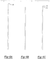
- the point 88 is a relatively sharp point defined at the dominant peak of the graph. This portion of the graph is magnified in Figure 6A .
- a vibrating blade in the frequency domain would generally appear as a flat top on the dominant peak rather than a sharp point. This is shwon in Figure 6B .
- Each point of the generally flat top would represent a different, but numerically close frequency.
- vibration can be identified if the processor detects a sequential series of frequencies having substantially the same magnitude in the frequency domain.
- Figs. 6B and 6C have lower height than 6A since the energy associated the pressure waves is spread across a wider (although still narrow) frequency band.
- the computational resources on an engine control unit can be limited or scarce and FFT (frequency) calculations can be numerically demanding.
- FFT frequency
- embodiments of the invention can be practiced that are less computationally intensive. Despite being less computationally intensive, such embodiments can be applied to monitor the health of the turbine engine but also to execute control commands. These embodiments may not be as accurate as the FFT analysis, but can be sufficiently accurate and can also be implemented with existing electronic engine controller (EEC) hardware.
- EEC electronic engine controller
- Velocity can be assessed with a variable threshold comparator plus pulse shaping and counting.
- a first comparator threshold associated with the exemplary embodiment is referenced at line 96.
- Respective pulses of pressure associated with the exemplary embodiment last between points referenced at 98 and 100, 102 and 104, as well as 106 and 108. The beginning and ending of a pulse is defined when the curve intersects the first comparator threshold 96.
- Counting the number of pulses over time corresponds to the frequency and therefore the velocity of the blades nearer to the sensor (such as the sensor 62 shown in Figures 1 , 5A and 5B ).
- the position of the first comparator threshold can be adjustable such that only pulses from the blades nearer to the sensor are captured.
- a second comparator threshold associated with the exemplary embodiment is referenced at line 110.
- the second (or lower) comparator threshold 110 will capture the pulses of both the nearer and further propeller rows.
- the count of pulses based on the second comparator threshold 110 will be greater than the count of pulses based on the first comparator threshold 96.
- the difference of the two counts corresponds to the frequency of the lower amplitude train (the series of lower amplitude pulses over time) and therefore the velocity of the blades further away from the sensor.
- Both the first and second comparator thresholds can be adjustable to compensate for amplitude changes.
- a track order filter combined with the above could be use to further extract information / parameters without the need for frequency analysis.
- a track order filter is a digital filter which is tuned for a particular frequency which can be changed by an algorithm. Normally this can be achieved without too much computational resources but allow an extraction of the signal amplitude at a particular frequency. So if the frequency has been calculated as described above in the time domain, then the filter can be tuned to obtain the amplitude of the signal at that frequency. By adjusting the bandwidth of the filter it should be possible to discriminate further parameters (like vibration, balance, etc.).
- Unbalance in a propeller can also be identified by the appearance of the wave form in the frequency domain.
- the point 88 is a single, relatively sharp point defined at the dominant peak of the graph. If the propeller is unbalanced, the wave form would display two relatively sharp points, close to one another, and having slightly different magnitudes. The two points correspond to different portions of the propeller and thus have the same frequency. However, the magnitude of the points would be different as a result of the imbalance.
- Figure 6C shows the two points referenced at 90 and 92. The points are shown adjacent to one another for illustrative purposes (they would have the same frequency as thus overlap along the x-axis of a graph in the frequency domain). Thus, imbalance can be identified if the processor detects at least two different magnitudes having substantially the same frequency in the frequency domain.
- pressure waves can be positive and also negative, depending on the position of the blades and the direction of rotation.
- pressure waves can be positive or negative depending on the position of the sensor 62, whether the sensor 62 is upstream or downstream as well as the flight condition. For example, if the rotation direction in Figs. 5A and 5B were opposite from the direction currently indicated, then the pressure waves would be negative. It is further noted that this would be the case when, for example, the pilot command to break when landing (i.e. reverse the pitch of the blades) so in the same engine depending of flight condition we will have both positive waves as well as negative waves.
- Embodiments of the invention can be practiced that are capable of determining fan parameters based on positive or negative pressure waves.
- the exemplary embodiment could also be applied to give an indication of ice formation and thus define an embodiment of another invention.
- the formation of ice will affect the distance 82 or 76 shown in Figs. 5A and 5B and will also therefore affect the signals illustrated in Figure 4 .
- the identification of ice formation is a desirable parameter for overall engine control.
- Anti-icing systems such as those located on the moving frame of reference (the blades), can require some mechanism or feature to communicate the presence of ice from the moving frame of reference to the static frame of reference (the nacelle for example) where the electronics can be located. Applying the exemplary embodiment to determine ice formation could be useful individually or in combination with other ice detection systems to acquire information about ice formation and anti-icing system effectiveness.
Landscapes
- Engineering & Computer Science (AREA)
- Chemical & Material Sciences (AREA)
- Combustion & Propulsion (AREA)
- Mechanical Engineering (AREA)
- General Engineering & Computer Science (AREA)
- Physics & Mathematics (AREA)
- General Physics & Mathematics (AREA)
- Measurement Of Mechanical Vibrations Or Ultrasonic Waves (AREA)
- Measuring Fluid Pressure (AREA)
- Structures Of Non-Positive Displacement Pumps (AREA)
Claims (15)
- Vorrichtung, mit
einem ersten Gebläse (38), das einen Nabenabschnitt (42) und mehrere sich vom Nabenabschnitt (42) radial auswärts erstreckende Schaufeln (46) aufweist;
einem Turbinenmotor (10), der dazu betriebsfähig ist, das erste Gebläse (38) um eine Rotationsachse (24) zu drehen;
einem Sensor (62), der vom ersten Gebläse (38) entlang der Rotationsachse (24) beabstandet und dazu angeordnet ist, einen sich durch Rotation der Schaufeln (46) ändernden Umgebungsdruck außerhalb des Turbinenmotors (10) zu erfassen, wobei der Sensor (62) dazu betriebsfähig ist, ein dem erfassten Druck entsprechendes Signal auszugeben; und
einem Prozessor (66), der mit dem Turbinenmotor (10) und dem Sensor (62) betriebsfähig so gekoppelt ist, dass der Prozessor (66) dazu betriebsfähig ist, das Signal vom Sensor (62) zu empfangen und den Betrieb des Turbinenmotors (10) in Antwort auf das Signal zu ändern und eine Geschwindigkeit des ersten Gebläses (38) zu ändern,
wobei der Prozessor (66) dazu betriebsfähig ist, den in einem Zeitbereich erfassten Druck mittels einer schnellen Fourier-Transformation in einen Frequenzbereich umzuwandeln und eine Steigung der Schaufeln (46) aus der erfassten zeitlichen Schwankung des Umgebungsdrucks zu ermitteln. - Vorrichtung nach Anspruch 1, wobei der Turbinenmotor (10) in einer Triebwerksgondel (14) aufgenommen ist, und wobei zumindest ein Teil des Sensors (62) bündig mit einer äußeren Oberfläche (94) der Triebwerksgondel (14) ist,
wobei der Sensor (62) ferner als betriebsfähig zum Erfassen eines Schallpegels bestimmt ist. - Vorrichtung nach Anspruch 1, ferner umfassend:
ein zweites Gebläse (40), das vom ersten Gebläse (38) beabstandet ist und einen Nabenabschnitt (44) sowie mehrere sich vom Nabenabschnitt (44) radial auswärts erstreckende Schaufeln (48) aufweist, wobei der Turbinenmotor (10) betriebsfähig mit dem zweiten Gebläse (40) gekoppelt ist, um das zweite Gebläse (40) um die Rotationsachse (24) zu drehen, und der Sensor (62) dazu angeordnet ist, gleichzeitig den durch Rotation der Schaufeln (46) des ersten Gebläses (38) und durch Rotation der Schaufeln (48) des zweiten Gebläses (40) geänderten Umgebungsdruck außerhalb des Turbinenmotors (10) zu erfassen. - Verfahren mit den Schritten:Bereitstellen eines Turbinenmotors (10) und mindestens eines Propellers (38, 40);Anordnen eines Sensors (62) stromaufwärts oder stromabwärts des mindestens einen Propellers (38, 40);dynamisches Erfassen der Schwankung des Umgebungsdrucks mittels des Sensors (62);Bestimmen der Geschwindigkeit des mindestens einen Propellers (38, 40) durch Erfassen einer von den Schaufeln (46, 48) des Propellers (38, 40) erzeugten Druckschwankung; undErmitteln einer Steigung der Schaufeln (46, 48) des Propellers (38, 40) aus der erfassten zeitlichen Schwankung des Umgebungsdrucks.
- Verfahren nach Anspruch 4, ferner umfassend den folgenden Schritt:
Ändern des Betriebs des Turbinenmotors (10) in Echtzeit in Antwort auf die aus der erfassten Druckschwankung abgeleitete Geschwindigkeit. - Verfahren nach Anspruch 4, wobei der Schritt des Bestimmens ferner die Schritte umfasst:dynamisches Erfassen des Drucks im Zeitbereich; undUmwandeln der im Zeitbereich erfassten Druckdaten in den Frequenzbereich mittels einer schnellen Fourier-Transformation.
- Verfahren nach Anspruch 6, wobei der Schritt des Bestimmens ferner die Schritte umfasst:
Zuordnen der im Frequenzbereich den größten Betrag aufweisenden Frequenz zur Winkelgeschwindigkeit des Propellers (38, 40). - Verfahren nach Anspruch 7, wobei der Schritt des Zuordnens ferner den Schritt umfasst:
Teilen der Frequenz mit dem größten Betrag im Frequenzbereich durch die Anzahl der Schaufeln (46, 48) des mindestens einen Propellers (38, 40), um die Winkelgeschwindigkeit des Propellers (38, 40) zu bestimmen. - Verfahren nach Anspruch 4, wobei der Schritt des Ermittelns ferner die Schritte umfasst:Leiten eines Signals vom Sensor (62) zu einem Prozessor (66), wobei das Signal der erfassten zeitlichen Schwankung des Umgebungsdrucks entspricht; undHerausfiltern im Wesentlichen des gesamten Rauschens aus dem Signal,oder Berechnen einer Amplitude und/oder einer Anstiegs- und Abfallzeit eines Abschnitts der erfassten zeitlichen Schwankung des Umgebungsdrucks,oder Vergleichen der erfassten zeitlichen Schwankung des Umgebungsdrucks mit einer vorbestimmten Wellenform.
- Verfahren nach Anspruch 4, ferner umfassend die Schritte:
dynamisches Erfassen des Umgebungsdrucks mit dem Sensor (62); und Erkennen einer Vibration in den Schaufeln (46, 48) des mindestens einen Propellers (38, 40) durch den Schritt des Erfassens. - Verfahren nach Anspruch 10, wobei der Schritt des Erkennens ferner die Schritte umfasst:Umwandeln der erfassten zeitlichen Schwankung des Umgebungsdrucks in den Frequenzbereich mittels einer schnellen Fourier-Transformation; undErfassen einer fortlaufenden Frequenzserie in den umgewandelten Umgebungsdruckdaten, wobei die fortlaufende Frequenzserie im Frequenzbereich im Wesentlichen denselben Betrag aufweist.
- Verfahren nach Anspruch 4, ferner umfassend die Schritte:dynamisches Erfassen der Schwankung des Umgebungsdrucks mit dem Sensor (62); undErkennen einer Unwucht in dem mindestens einen Propeller (38, 40) durch den Schritt des Erfassens.
- Verfahren nach Anspruch 12, wobei der Schritt des Erkennens ferner die Schritte umfasst:Umwandeln der erfassten zeitlichen Schwankung des Umgebungsdrucks in den Frequenzbereich mittels einer schnellen Fourier-Transformation; undErfassen mindestens zweier unterschiedlicher Beträge mit im Wesentlichen derselben Frequenz im Frequenzbereich.
- Verfahren nach Anspruch 4, wobei der Schritt des Bestimmens ferner die Schritte umfasst:dynamisches Erfassen des Drucks im Zeitbereich; undUmwandeln der im Zeitbereich erfassten Druckdaten in die Geschwindigkeit mindestens eines sich drehenden Propellers (38, 40) mittels eines Komparators mit variablem Schwellenwert.
- Verfahren nach Anspruch 14, ferner umfassend den Schritt des Bereitstellens eines weiteren Propellers (38, 40),
wobei der Schritt des Umwandelns die Schritte umfasst:Anwenden eines ersten Schwellenwert-Komparators über eine vorbestimmte Zeit, um eine erste Anzahl von Druckpulsen zu erkennen, deren Betrag größer als ein erster vorbestimmter Betrag ist; undAnwenden eines zweiten Schwellenwert-Komparators über die vorbestimmte Zeit, um eine zweite Anzahl von Druckpulsen zu erkennen, deren Betrag größer als ein zweiter vorbestimmter Betrag und kleiner als der erste vorbestimmte Betrag ist.
Applications Claiming Priority (2)
| Application Number | Priority Date | Filing Date | Title |
|---|---|---|---|
| US12/723,835 US8752394B2 (en) | 2010-03-15 | 2010-03-15 | Determining fan parameters through pressure monitoring |
| PCT/US2011/028507 WO2011152914A2 (en) | 2010-03-15 | 2011-03-15 | Determining fan parameters through pressure monitoring |
Publications (4)
| Publication Number | Publication Date |
|---|---|
| EP2547893A2 EP2547893A2 (de) | 2013-01-23 |
| EP2547893A4 EP2547893A4 (de) | 2018-01-03 |
| EP2547893B1 true EP2547893B1 (de) | 2019-05-08 |
| EP2547893B8 EP2547893B8 (de) | 2019-07-10 |
Family
ID=44558603
Family Applications (1)
| Application Number | Title | Priority Date | Filing Date |
|---|---|---|---|
| EP11790135.5A Active EP2547893B8 (de) | 2010-03-15 | 2011-03-15 | Ermittlung von lüfterparametern durch drucküberwachung |
Country Status (6)
| Country | Link |
|---|---|
| US (1) | US8752394B2 (de) |
| EP (1) | EP2547893B8 (de) |
| JP (1) | JP5819395B2 (de) |
| CN (1) | CN103429852B (de) |
| CA (1) | CA2793305C (de) |
| WO (1) | WO2011152914A2 (de) |
Families Citing this family (29)
| Publication number | Priority date | Publication date | Assignee | Title |
|---|---|---|---|---|
| US8990026B2 (en) * | 2012-01-03 | 2015-03-24 | General Electric Company | System and method for detecting combustion hardware damage |
| US20160130949A1 (en) | 2012-01-31 | 2016-05-12 | United Technologies Corporation | Low noise turbine for geared turbofan engine |
| US8246292B1 (en) * | 2012-01-31 | 2012-08-21 | United Technologies Corporation | Low noise turbine for geared turbofan engine |
| US20140007591A1 (en) * | 2012-07-03 | 2014-01-09 | Alexander I. Khibnik | Advanced tip-timing measurement blade mode identification |
| US9624834B2 (en) | 2012-09-28 | 2017-04-18 | United Technologies Corporation | Low noise compressor rotor for geared turbofan engine |
| US20160138474A1 (en) | 2012-09-28 | 2016-05-19 | United Technologies Corporation | Low noise compressor rotor for geared turbofan engine |
| EP2971594B1 (de) | 2013-03-14 | 2020-01-08 | Rolls-Royce Corporation | Steuerung eines hybriden turboelektrischen luftantriebssystems |
| US10605172B2 (en) | 2013-03-14 | 2020-03-31 | United Technologies Corporation | Low noise turbine for geared gas turbine engine |
| US11719161B2 (en) | 2013-03-14 | 2023-08-08 | Raytheon Technologies Corporation | Low noise turbine for geared gas turbine engine |
| US9203459B2 (en) * | 2013-04-18 | 2015-12-01 | Sikorsky Aircraft Corporation | Harmonic data transfer in rotary wing aircraft |
| CN105043713B (zh) * | 2015-06-23 | 2017-06-16 | 中国航空工业集团公司西安飞机设计研究所 | 一种舱体外表面压力测试方法 |
| US20170260871A1 (en) * | 2016-03-08 | 2017-09-14 | General Electric Company | Engine Health Monitoring Using Acoustic Sensors |
| US20170330547A1 (en) * | 2016-05-10 | 2017-11-16 | GM Global Technology Operations LLC | Methods and systems for reducing a pressure wave |
| EP3296195B1 (de) | 2016-09-16 | 2019-10-30 | Ratier-Figeac SAS | Propellergesundheitsüberwachung |
| US10071820B2 (en) * | 2016-09-19 | 2018-09-11 | Pratt & Whitney Canada Corp. | Inclement weather detection for aircraft engines |
| EP3462180A1 (de) * | 2017-10-02 | 2019-04-03 | Siemens Aktiengesellschaft | Verfahren und vorrichtung zur rotationsüberwachung |
| GB201719538D0 (en) * | 2017-11-24 | 2018-01-10 | Rolls Royce Plc | Gas turbine engine |
| US10745110B2 (en) * | 2018-06-29 | 2020-08-18 | Pratt & Whitney Canada Corp. | Propeller blade synchrophasing using phonic wheel |
| CN109000776B (zh) * | 2018-09-28 | 2020-09-04 | 北京化工大学 | 一种涡轮机叶片振动参数分析方法及分析装置 |
| CN111380093B (zh) * | 2018-12-28 | 2022-03-18 | 宁波方太厨具有限公司 | 一种自清洁吸油烟机及自清洁控制方法 |
| GB201903646D0 (en) * | 2019-03-18 | 2019-05-01 | Rolls Royce Plc | Condition determination of a gas turbine engine |
| FR3094088B1 (fr) * | 2019-03-19 | 2021-04-16 | Airbus Operations Sas | Procédé et système de détection et d’identification de vibrations d’un aéronef. |
| US11506571B2 (en) | 2019-09-09 | 2022-11-22 | Rohr, Inc. | System and method for gathering flight load data |
| CN112664328B (zh) * | 2019-10-15 | 2024-07-23 | 通用电气公司 | 用于控制无涵道发动机的系统和方法 |
| CN112485013B (zh) * | 2020-11-16 | 2021-07-30 | 中国空气动力研究与发展中心高速空气动力研究所 | 一种带涡轮动力模拟的单独涡扇发动机短舱表面测压试验装置及测压试验方法 |
| CN113376397B (zh) * | 2021-04-30 | 2023-02-03 | 北京航天动力研究所 | 一种用于超低温液氢泵的超高转速测量装置及方法 |
| CN114563155B (zh) * | 2022-03-14 | 2023-05-19 | 中国空气动力研究与发展中心低速空气动力研究所 | 一种开式转子气动性能评估试验装置 |
| CN114857066B (zh) * | 2022-04-29 | 2023-07-11 | 三一重机有限公司 | 液压驱动风扇控制方法、散热装置及作业机械 |
| CN117073958B (zh) * | 2023-10-17 | 2023-12-08 | 中国航空工业集团公司沈阳空气动力研究所 | 一种开式转子发动机转子及静子叶片高速风洞试验装置 |
Family Cites Families (34)
| Publication number | Priority date | Publication date | Assignee | Title |
|---|---|---|---|---|
| US4967550A (en) * | 1987-04-28 | 1990-11-06 | Rolls-Royce Plc | Active control of unsteady motion phenomena in turbomachinery |
| US5072580A (en) * | 1989-02-27 | 1991-12-17 | United Technologies Corporation | System for operating gas turbine jet engine with fan damage |
| US4951461A (en) * | 1989-03-20 | 1990-08-28 | General Electric Company | Power turbine support arrangement |
| JP3276214B2 (ja) | 1992-08-31 | 2002-04-22 | マツダ株式会社 | 車両の振動低減装置 |
| US5463458A (en) * | 1993-12-16 | 1995-10-31 | General Electric Company | Optical sensor for duct fan discharge mach numbers |
| US5719791A (en) | 1995-03-17 | 1998-02-17 | Georgia Tech Research Corporation | Methods, apparatus and systems for real time identification and control of modes of oscillation |
| US5686669A (en) | 1996-02-29 | 1997-11-11 | Monitoring Technology Corporation | Apparatus and method for analyzing the condition and performance of turbomachines by processing signals representing rotor motion |
| US5744723A (en) | 1996-05-10 | 1998-04-28 | Csi Technology, Inc. | Method for determining rotational speed from machine vibration data |
| US5789678A (en) | 1996-10-22 | 1998-08-04 | General Electric Company | Method for reducing noise and/or vibration from multiple rotating machines |
| US7011498B2 (en) * | 1998-04-03 | 2006-03-14 | Athena Technologies, Inc. | Optimization method for power generation systems |
| DE19857552A1 (de) | 1998-12-14 | 2000-06-15 | Rolls Royce Deutschland | Verfahren zum Erkennen eines Wellenbruches in einer Strömungskraftmaschine |
| CN1137796C (zh) | 1999-08-20 | 2004-02-11 | 三菱电机株式会社 | 线切割加工装置 |
| US7262591B2 (en) * | 2000-12-20 | 2007-08-28 | Micronas Gmbh | Technique for sensing the rotational speed and angular position of a rotating wheel |
| US7305094B2 (en) | 2001-01-12 | 2007-12-04 | University Of Dayton | System and method for actively damping boom noise in a vibro-acoustic enclosure |
| US6445995B1 (en) | 2001-01-26 | 2002-09-03 | General Electric Company | Vibration sensing in gas turbine engine |
| IL144010A (en) | 2001-06-26 | 2006-04-10 | Engines Pdm Ltd | Universal diagnostic method and system for engines |
| US6768607B2 (en) | 2001-08-22 | 2004-07-27 | Hitachi Global Storage Technologies Netherlands B.V. | Adaptive dual-frequency notch filter |
| JP4056232B2 (ja) | 2001-08-23 | 2008-03-05 | 三菱重工業株式会社 | ガスタービン制御装置、ガスタービンシステム及びガスタービン遠隔監視システム |
| US7272234B2 (en) * | 2002-04-04 | 2007-09-18 | Brigham Young University | Multi-channel active control system and method for the reduction of tonal noise from an axial fan |
| GB2387522B (en) | 2002-04-10 | 2005-09-28 | Hobelsberger Max | Tunable active sound absorbers |
| FR2840358B1 (fr) | 2002-05-28 | 2006-09-15 | Snecma Moteurs | Procede et systeme de detection d'endommagement de rotor d'un moteur d'aeronef |
| US6823253B2 (en) | 2002-11-27 | 2004-11-23 | General Electric Company | Methods and apparatus for model predictive control of aircraft gas turbine engines |
| AU2004213513B2 (en) * | 2003-02-18 | 2009-07-16 | Technical University Of Denmark | Method of controlling aerodynamic load of a wind turbine based on local blade flow measurement |
| WO2005106293A2 (en) | 2004-04-15 | 2005-11-10 | Federal-Mogul Corporation | An integrated sensor-seal module for detecting angular position of a crankshaft |
| US7086834B2 (en) * | 2004-06-10 | 2006-08-08 | General Electric Company | Methods and apparatus for rotor blade ice detection |
| WO2006059976A1 (en) | 2004-12-01 | 2006-06-08 | United Technologies Corporation | Turbine engine with a rotor speed sensor and corresponding operating method |
| US7406820B2 (en) | 2005-03-25 | 2008-08-05 | Honeywell International Inc. | System and method for turbine engine adaptive control for mitigation of instabilities |
| US7603844B2 (en) | 2005-10-19 | 2009-10-20 | General Electric Company | Gas turbine engine assembly and methods of assembling same |
| US7827803B1 (en) * | 2006-09-27 | 2010-11-09 | General Electric Company | Method and apparatus for an aerodynamic stability management system |
| US8308423B2 (en) * | 2006-10-12 | 2012-11-13 | United Technologies Corporation | Variable area fan nozzle for accommodating a foreign object strike event |
| CN101675325A (zh) * | 2007-03-29 | 2010-03-17 | 维斯塔斯风力系统有限公司 | 用于检查风力涡轮机的至少一个转子叶片的方法以及用于风力涡轮机的至少一个转子叶片的检查系统 |
| US20100284785A1 (en) * | 2007-12-28 | 2010-11-11 | Aspi Rustom Wadia | Fan Stall Detection System |
| US8313279B2 (en) | 2008-04-21 | 2012-11-20 | General Electric Company | Dual rotor vibration monitoring |
| FR2932850B1 (fr) * | 2008-06-23 | 2010-08-13 | Snecma | Procede et systeme de determination de la position angulaire d'un rotor de turboreacteur. |
-
2010
- 2010-03-15 US US12/723,835 patent/US8752394B2/en active Active
-
2011
- 2011-03-15 CN CN201180024012.2A patent/CN103429852B/zh not_active Expired - Fee Related
- 2011-03-15 JP JP2013500153A patent/JP5819395B2/ja not_active Expired - Fee Related
- 2011-03-15 WO PCT/US2011/028507 patent/WO2011152914A2/en not_active Ceased
- 2011-03-15 EP EP11790135.5A patent/EP2547893B8/de active Active
- 2011-03-15 CA CA2793305A patent/CA2793305C/en not_active Expired - Fee Related
Non-Patent Citations (1)
| Title |
|---|
| None * |
Also Published As
| Publication number | Publication date |
|---|---|
| EP2547893A2 (de) | 2013-01-23 |
| EP2547893B8 (de) | 2019-07-10 |
| CA2793305A1 (en) | 2011-12-08 |
| WO2011152914A2 (en) | 2011-12-08 |
| US20110219741A1 (en) | 2011-09-15 |
| WO2011152914A3 (en) | 2014-03-20 |
| US8752394B2 (en) | 2014-06-17 |
| CN103429852A (zh) | 2013-12-04 |
| CN103429852B (zh) | 2015-12-16 |
| JP5819395B2 (ja) | 2015-11-24 |
| EP2547893A4 (de) | 2018-01-03 |
| CA2793305C (en) | 2016-10-11 |
| JP2013530331A (ja) | 2013-07-25 |
Similar Documents
| Publication | Publication Date | Title |
|---|---|---|
| US8752394B2 (en) | Determining fan parameters through pressure monitoring | |
| EP0654161B1 (de) | Verfahren zur überwachung und steuerung eines verdichters und vorrichtung hierfür. | |
| EP0654162B1 (de) | Vorrichtung zur verkrustungsdetektion eines axialverdichters. | |
| EP0654163B1 (de) | Verfahren und vorrichtung zur überwachung der vibrationserregung eines axialverdichters. | |
| US7698942B2 (en) | Turbine engine stall warning system | |
| JP4111869B2 (ja) | 航空機エンジンのロータへの損傷を検知するための方法およびシステム | |
| US6659712B2 (en) | Apparatus and method for detecting a damaged rotary machine aerofoil | |
| CN101592590B (zh) | 一种转动叶片故障间接诊断技术 | |
| US6932560B2 (en) | Apparatus and method for detecting an impact on a rotor blade | |
| US11353034B2 (en) | Method and device for determining an indicator for a prediction of an instability in a compressor and use thereof | |
| CN114981633A (zh) | 用于监测飞行器的涡轮发动机上的旋转轴的扭转的方法 | |
| Murray III et al. | Detection of rotor forced response vibrations using stationary pressure transducers in a multistage axial compressor | |
| RU2411466C1 (ru) | Способ обнаружения резонансных колебаний лопаток ротора турбомашины | |
| CN113358210A (zh) | 一种基于压力脉动的增压器涡轮叶片振动监测方法 | |
| Rinaldi et al. | Dynamic pressure as a measure of gas turbine engine (GTE) performance | |
| KR100296672B1 (ko) | 축류압축기의오염을검출하기위한프로세스및장치 | |
| RK et al. | Observations on Bladed Disk Vibrations of an Aero Engine-Experiences during Testing. |
Legal Events
| Date | Code | Title | Description |
|---|---|---|---|
| PUAI | Public reference made under article 153(3) epc to a published international application that has entered the european phase |
Free format text: ORIGINAL CODE: 0009012 |
|
| 17P | Request for examination filed |
Effective date: 20121015 |
|
| AK | Designated contracting states |
Kind code of ref document: A2 Designated state(s): AL AT BE BG CH CY CZ DE DK EE ES FI FR GB GR HR HU IE IS IT LI LT LU LV MC MK MT NL NO PL PT RO RS SE SI SK SM TR |
|
| DAX | Request for extension of the european patent (deleted) | ||
| R17D | Deferred search report published (corrected) |
Effective date: 20140320 |
|
| A4 | Supplementary search report drawn up and despatched |
Effective date: 20171130 |
|
| RIC1 | Information provided on ipc code assigned before grant |
Ipc: F02C 9/28 20060101ALI20171124BHEP Ipc: F02K 3/072 20060101ALI20171124BHEP Ipc: F02K 3/06 20060101AFI20171124BHEP Ipc: F01D 21/10 20060101ALI20171124BHEP Ipc: F01D 21/02 20060101ALI20171124BHEP Ipc: G01P 3/48 20060101ALI20171124BHEP |
|
| GRAP | Despatch of communication of intention to grant a patent |
Free format text: ORIGINAL CODE: EPIDOSNIGR1 |
|
| STAA | Information on the status of an ep patent application or granted ep patent |
Free format text: STATUS: GRANT OF PATENT IS INTENDED |
|
| INTG | Intention to grant announced |
Effective date: 20181030 |
|
| GRAS | Grant fee paid |
Free format text: ORIGINAL CODE: EPIDOSNIGR3 |
|
| GRAA | (expected) grant |
Free format text: ORIGINAL CODE: 0009210 |
|
| STAA | Information on the status of an ep patent application or granted ep patent |
Free format text: STATUS: THE PATENT HAS BEEN GRANTED |
|
| GRAT | Correction requested after decision to grant or after decision to maintain patent in amended form |
Free format text: ORIGINAL CODE: EPIDOSNCDEC |
|
| AK | Designated contracting states |
Kind code of ref document: B1 Designated state(s): AL AT BE BG CH CY CZ DE DK EE ES FI FR GB GR HR HU IE IS IT LI LT LU LV MC MK MT NL NO PL PT RO RS SE SI SK SM TR |
|
| REG | Reference to a national code |
Ref country code: GB Ref legal event code: FG4D |
|
| REG | Reference to a national code |
Ref country code: CH Ref legal event code: EP Ref country code: AT Ref legal event code: REF Ref document number: 1130483 Country of ref document: AT Kind code of ref document: T Effective date: 20190515 |
|
| REG | Reference to a national code |
Ref country code: DE Ref legal event code: R096 Ref document number: 602011058807 Country of ref document: DE |
|
| RAP2 | Party data changed (patent owner data changed or rights of a patent transferred) |
Owner name: ROLLS-ROYCE CORPORATION |
|
| REG | Reference to a national code |
Ref country code: IE Ref legal event code: FG4D |
|
| REG | Reference to a national code |
Ref country code: CH Ref legal event code: PK Free format text: BERICHTIGUNG B8 |
|
| REG | Reference to a national code |
Ref country code: NL Ref legal event code: MP Effective date: 20190508 |
|
| REG | Reference to a national code |
Ref country code: LT Ref legal event code: MG4D |
|
| PG25 | Lapsed in a contracting state [announced via postgrant information from national office to epo] |
Ref country code: ES Free format text: LAPSE BECAUSE OF FAILURE TO SUBMIT A TRANSLATION OF THE DESCRIPTION OR TO PAY THE FEE WITHIN THE PRESCRIBED TIME-LIMIT Effective date: 20190508 Ref country code: NL Free format text: LAPSE BECAUSE OF FAILURE TO SUBMIT A TRANSLATION OF THE DESCRIPTION OR TO PAY THE FEE WITHIN THE PRESCRIBED TIME-LIMIT Effective date: 20190508 Ref country code: LT Free format text: LAPSE BECAUSE OF FAILURE TO SUBMIT A TRANSLATION OF THE DESCRIPTION OR TO PAY THE FEE WITHIN THE PRESCRIBED TIME-LIMIT Effective date: 20190508 Ref country code: HR Free format text: LAPSE BECAUSE OF FAILURE TO SUBMIT A TRANSLATION OF THE DESCRIPTION OR TO PAY THE FEE WITHIN THE PRESCRIBED TIME-LIMIT Effective date: 20190508 Ref country code: FI Free format text: LAPSE BECAUSE OF FAILURE TO SUBMIT A TRANSLATION OF THE DESCRIPTION OR TO PAY THE FEE WITHIN THE PRESCRIBED TIME-LIMIT Effective date: 20190508 Ref country code: AL Free format text: LAPSE BECAUSE OF FAILURE TO SUBMIT A TRANSLATION OF THE DESCRIPTION OR TO PAY THE FEE WITHIN THE PRESCRIBED TIME-LIMIT Effective date: 20190508 Ref country code: PT Free format text: LAPSE BECAUSE OF FAILURE TO SUBMIT A TRANSLATION OF THE DESCRIPTION OR TO PAY THE FEE WITHIN THE PRESCRIBED TIME-LIMIT Effective date: 20190908 Ref country code: SE Free format text: LAPSE BECAUSE OF FAILURE TO SUBMIT A TRANSLATION OF THE DESCRIPTION OR TO PAY THE FEE WITHIN THE PRESCRIBED TIME-LIMIT Effective date: 20190508 Ref country code: NO Free format text: LAPSE BECAUSE OF FAILURE TO SUBMIT A TRANSLATION OF THE DESCRIPTION OR TO PAY THE FEE WITHIN THE PRESCRIBED TIME-LIMIT Effective date: 20190808 |
|
| PG25 | Lapsed in a contracting state [announced via postgrant information from national office to epo] |
Ref country code: LV Free format text: LAPSE BECAUSE OF FAILURE TO SUBMIT A TRANSLATION OF THE DESCRIPTION OR TO PAY THE FEE WITHIN THE PRESCRIBED TIME-LIMIT Effective date: 20190508 Ref country code: GR Free format text: LAPSE BECAUSE OF FAILURE TO SUBMIT A TRANSLATION OF THE DESCRIPTION OR TO PAY THE FEE WITHIN THE PRESCRIBED TIME-LIMIT Effective date: 20190809 Ref country code: RS Free format text: LAPSE BECAUSE OF FAILURE TO SUBMIT A TRANSLATION OF THE DESCRIPTION OR TO PAY THE FEE WITHIN THE PRESCRIBED TIME-LIMIT Effective date: 20190508 Ref country code: BG Free format text: LAPSE BECAUSE OF FAILURE TO SUBMIT A TRANSLATION OF THE DESCRIPTION OR TO PAY THE FEE WITHIN THE PRESCRIBED TIME-LIMIT Effective date: 20190808 |
|
| REG | Reference to a national code |
Ref country code: AT Ref legal event code: MK05 Ref document number: 1130483 Country of ref document: AT Kind code of ref document: T Effective date: 20190508 |
|
| PG25 | Lapsed in a contracting state [announced via postgrant information from national office to epo] |
Ref country code: RO Free format text: LAPSE BECAUSE OF FAILURE TO SUBMIT A TRANSLATION OF THE DESCRIPTION OR TO PAY THE FEE WITHIN THE PRESCRIBED TIME-LIMIT Effective date: 20190508 Ref country code: CZ Free format text: LAPSE BECAUSE OF FAILURE TO SUBMIT A TRANSLATION OF THE DESCRIPTION OR TO PAY THE FEE WITHIN THE PRESCRIBED TIME-LIMIT Effective date: 20190508 Ref country code: EE Free format text: LAPSE BECAUSE OF FAILURE TO SUBMIT A TRANSLATION OF THE DESCRIPTION OR TO PAY THE FEE WITHIN THE PRESCRIBED TIME-LIMIT Effective date: 20190508 Ref country code: AT Free format text: LAPSE BECAUSE OF FAILURE TO SUBMIT A TRANSLATION OF THE DESCRIPTION OR TO PAY THE FEE WITHIN THE PRESCRIBED TIME-LIMIT Effective date: 20190508 Ref country code: DK Free format text: LAPSE BECAUSE OF FAILURE TO SUBMIT A TRANSLATION OF THE DESCRIPTION OR TO PAY THE FEE WITHIN THE PRESCRIBED TIME-LIMIT Effective date: 20190508 Ref country code: SK Free format text: LAPSE BECAUSE OF FAILURE TO SUBMIT A TRANSLATION OF THE DESCRIPTION OR TO PAY THE FEE WITHIN THE PRESCRIBED TIME-LIMIT Effective date: 20190508 |
|
| REG | Reference to a national code |
Ref country code: DE Ref legal event code: R097 Ref document number: 602011058807 Country of ref document: DE |
|
| PG25 | Lapsed in a contracting state [announced via postgrant information from national office to epo] |
Ref country code: IT Free format text: LAPSE BECAUSE OF FAILURE TO SUBMIT A TRANSLATION OF THE DESCRIPTION OR TO PAY THE FEE WITHIN THE PRESCRIBED TIME-LIMIT Effective date: 20190508 Ref country code: SM Free format text: LAPSE BECAUSE OF FAILURE TO SUBMIT A TRANSLATION OF THE DESCRIPTION OR TO PAY THE FEE WITHIN THE PRESCRIBED TIME-LIMIT Effective date: 20190508 |
|
| PLBE | No opposition filed within time limit |
Free format text: ORIGINAL CODE: 0009261 |
|
| STAA | Information on the status of an ep patent application or granted ep patent |
Free format text: STATUS: NO OPPOSITION FILED WITHIN TIME LIMIT |
|
| PG25 | Lapsed in a contracting state [announced via postgrant information from national office to epo] |
Ref country code: TR Free format text: LAPSE BECAUSE OF FAILURE TO SUBMIT A TRANSLATION OF THE DESCRIPTION OR TO PAY THE FEE WITHIN THE PRESCRIBED TIME-LIMIT Effective date: 20190508 |
|
| 26N | No opposition filed |
Effective date: 20200211 |
|
| PG25 | Lapsed in a contracting state [announced via postgrant information from national office to epo] |
Ref country code: PL Free format text: LAPSE BECAUSE OF FAILURE TO SUBMIT A TRANSLATION OF THE DESCRIPTION OR TO PAY THE FEE WITHIN THE PRESCRIBED TIME-LIMIT Effective date: 20190508 |
|
| PG25 | Lapsed in a contracting state [announced via postgrant information from national office to epo] |
Ref country code: SI Free format text: LAPSE BECAUSE OF FAILURE TO SUBMIT A TRANSLATION OF THE DESCRIPTION OR TO PAY THE FEE WITHIN THE PRESCRIBED TIME-LIMIT Effective date: 20190508 |
|
| PG25 | Lapsed in a contracting state [announced via postgrant information from national office to epo] |
Ref country code: MC Free format text: LAPSE BECAUSE OF FAILURE TO SUBMIT A TRANSLATION OF THE DESCRIPTION OR TO PAY THE FEE WITHIN THE PRESCRIBED TIME-LIMIT Effective date: 20190508 |
|
| REG | Reference to a national code |
Ref country code: CH Ref legal event code: PL |
|
| REG | Reference to a national code |
Ref country code: BE Ref legal event code: MM Effective date: 20200331 |
|
| PG25 | Lapsed in a contracting state [announced via postgrant information from national office to epo] |
Ref country code: LU Free format text: LAPSE BECAUSE OF NON-PAYMENT OF DUE FEES Effective date: 20200315 |
|
| PG25 | Lapsed in a contracting state [announced via postgrant information from national office to epo] |
Ref country code: IE Free format text: LAPSE BECAUSE OF NON-PAYMENT OF DUE FEES Effective date: 20200315 Ref country code: LI Free format text: LAPSE BECAUSE OF NON-PAYMENT OF DUE FEES Effective date: 20200331 Ref country code: CH Free format text: LAPSE BECAUSE OF NON-PAYMENT OF DUE FEES Effective date: 20200331 |
|
| PG25 | Lapsed in a contracting state [announced via postgrant information from national office to epo] |
Ref country code: BE Free format text: LAPSE BECAUSE OF NON-PAYMENT OF DUE FEES Effective date: 20200331 |
|
| GBPC | Gb: european patent ceased through non-payment of renewal fee |
Effective date: 20200315 |
|
| PG25 | Lapsed in a contracting state [announced via postgrant information from national office to epo] |
Ref country code: GB Free format text: LAPSE BECAUSE OF NON-PAYMENT OF DUE FEES Effective date: 20200315 |
|
| PG25 | Lapsed in a contracting state [announced via postgrant information from national office to epo] |
Ref country code: MT Free format text: LAPSE BECAUSE OF FAILURE TO SUBMIT A TRANSLATION OF THE DESCRIPTION OR TO PAY THE FEE WITHIN THE PRESCRIBED TIME-LIMIT Effective date: 20190508 Ref country code: CY Free format text: LAPSE BECAUSE OF FAILURE TO SUBMIT A TRANSLATION OF THE DESCRIPTION OR TO PAY THE FEE WITHIN THE PRESCRIBED TIME-LIMIT Effective date: 20190508 |
|
| PG25 | Lapsed in a contracting state [announced via postgrant information from national office to epo] |
Ref country code: MK Free format text: LAPSE BECAUSE OF FAILURE TO SUBMIT A TRANSLATION OF THE DESCRIPTION OR TO PAY THE FEE WITHIN THE PRESCRIBED TIME-LIMIT Effective date: 20190508 Ref country code: IS Free format text: LAPSE BECAUSE OF FAILURE TO SUBMIT A TRANSLATION OF THE DESCRIPTION OR TO PAY THE FEE WITHIN THE PRESCRIBED TIME-LIMIT Effective date: 20190908 |
|
| PGFP | Annual fee paid to national office [announced via postgrant information from national office to epo] |
Ref country code: DE Payment date: 20230328 Year of fee payment: 13 |
|
| P01 | Opt-out of the competence of the unified patent court (upc) registered |
Effective date: 20230528 |
|
| REG | Reference to a national code |
Ref country code: DE Ref legal event code: R119 Ref document number: 602011058807 Country of ref document: DE |
|
| PG25 | Lapsed in a contracting state [announced via postgrant information from national office to epo] |
Ref country code: DE Free format text: LAPSE BECAUSE OF NON-PAYMENT OF DUE FEES Effective date: 20241001 |
|
| PG25 | Lapsed in a contracting state [announced via postgrant information from national office to epo] |
Ref country code: DE Free format text: LAPSE BECAUSE OF NON-PAYMENT OF DUE FEES Effective date: 20241001 |
|
| PGFP | Annual fee paid to national office [announced via postgrant information from national office to epo] |
Ref country code: FR Payment date: 20260323 Year of fee payment: 16 |