EP2548209B1 - Leitungsführungssystem für einen hochspannungstransformator - Google Patents
Leitungsführungssystem für einen hochspannungstransformator Download PDFInfo
- Publication number
- EP2548209B1 EP2548209B1 EP10712383.8A EP10712383A EP2548209B1 EP 2548209 B1 EP2548209 B1 EP 2548209B1 EP 10712383 A EP10712383 A EP 10712383A EP 2548209 B1 EP2548209 B1 EP 2548209B1
- Authority
- EP
- European Patent Office
- Prior art keywords
- sockets
- connection arrangement
- contact connection
- electrode
- routing system
- Prior art date
- Legal status (The legal status is an assumption and is not a legal conclusion. Google has not performed a legal analysis and makes no representation as to the accuracy of the status listed.)
- Active
Links
Images
Classifications
-
- H—ELECTRICITY
- H01—ELECTRIC ELEMENTS
- H01F—MAGNETS; INDUCTANCES; TRANSFORMERS; SELECTION OF MATERIALS FOR THEIR MAGNETIC PROPERTIES
- H01F27/00—Details of transformers or inductances, in general
- H01F27/02—Casings
- H01F27/04—Leading of conductors or axles through casings, e.g. for tap-changing arrangements
Definitions
- the invention relates to a multi-contact connection arrangement for the electrical connection of an electrical component with an electrical connection, a first socket and a second socket along a longitudinal axis aligned with each other, wherein the sockets are electrically connected to each other by means of a current band, wherein in the first socket a first socket pin and in the second socket a second locking pin can be inserted and the first locking pin is electrically connected to the first electrical connection, wherein support members are provided which are adapted for axially against each other moving and positioning the sockets.
- the invention further relates to a guide system with such a multi-contact arrangement.
- Such a multi-contact arrangement is known from JP 59 036 909 A already known.
- the multicontact connection arrangement disclosed therein has two mutually opposite sockets, which are connected to one another via a ribbon conductor. In the sockets pin bolts are inserted, which are each connected to an electrical component.
- the DE 27 46 566 A1 describes a bushing which is connected via strip conductors to the active parts of a transformer.
- High voltage electrical connections of electrical components such as high voltage transformers, circuit breakers or chokes must meet a variety of mechanical and electrical requirements.
- the connection and contact point of the electrical Component having an external electrical power supply network extensive insulation.
- high and extra high voltage applications such as 800 kV HVDC transformers, extensive barrier systems are required.
- An integral plug-in element forms a support, with which the wall elements are connectable, wherein the one-piece plug element is spatially spaced from the cable feedthrough and mechanically connects the support almost parallel arranged wall elements, wherein the holder and the fixation of the wall elements is formed such that the end face and at least one side surface of the respective wall elements rest on the support.
- a disadvantage of the existing cable routing systems in the prior art for high voltage applications is that the previous power connection is carried out by means of a feedthrough electrode by means of current bands in such a way that the current bands connected to the feedthrough electrode a pipe electrode are connected.
- the current bands are pulled out of the electrode to an accessible location and connected by means of a clamping piece on oil-side bushing bolts. Subsequently, the bushing is pushed back into the electrode, so that the current bands collect in the electrode.
- the receiving volume in the electrode interior of the lead-through electrode must be large enough to accommodate all current bands.
- the multicontact connection arrangement mentioned at the outset has the disadvantage that high demands are placed on the positioning of the components to be connected to one another.
- Object of the present invention is therefore to provide a multi-contact connection arrangement of the type mentioned, which allows a simple and secure installation of the electrical connection.
- the object is achieved in that the radial distance of the sockets relative to each other by means of spacer elements is adjustable, wherein the spacer elements and the current band are connectable to a first flange of the first socket and a second flange of the second socket.
- a multicontact connection arrangement in which the first electrical connection with a first plug pin and the tube electrode with a second plug pin are electrically connected and the first plug pin in a first socket and the second plug pin in a second socket can be inserted, wherein the sockets with a Current band are electrically connected.
- the sockets of the multi-contact connection arrangement are axially and / or radially displaceable relative to the longitudinal axis of the feedthrough electrode.
- the multi-contact connection arrangement can thus be arranged on a carriage within the feedthrough electrode.
- the multi-contact connection arrangement with flexible holding elements, for example by means of insulating springs within the feedthrough electrode and thus completely flexible in the radial and / or axial direction relative to the longitudinal axis of the Ensure feedthrough electrode.
- flexible holding elements for example by means of insulating springs within the feedthrough electrode and thus completely flexible in the radial and / or axial direction relative to the longitudinal axis of the Ensure feedthrough electrode.
- plastic elements having resilient properties for supporting the multi-contact interconnect assembly within the feedthrough electrode provides for possible flexible suspension of the aforementioned multi-contact interconnect assembly within the feedthrough electrode.
- the radial distance of the sockets relative to the longitudinal axis of the multi-contact connection arrangement can be predetermined by means of lockable spacer elements. This makes it possible to design the multi-contact connection arrangement for the respectively required connection application case so that with different network and component conditions, the standardized multi-contact connection arrangement relative to the radial distance is adapted only with respect to the spacer elements. As a result, a standardized production of the multi-contact connection arrangement, in particular the sockets to each other possible, so that in dependence on the respective electric current strength, the distance between the sockets by means of the spacer elements is adjustable. In particular, the sockets and locking pins can be used for different currents. Only the number of current bands in the multicontact arrangement is to be matched to the respective currents.
- the spacer elements are screwed within the multi-contact connection arrangement. Due to the axial and / or radial displaceability of the sockets relative to one another, the current band is advantageously guided by means of a guide at least partially relative to at least one of the sockets of the multicontact connection arrangement. Advantageously, this ensures that the current bands are guided relative to the sockets and thus even with a particular radial displacement relative to each other of the sockets it does not come to unwanted electrical interference, such as electrical transitions due to changed isolation distances.
- several current bands are arranged equidistant relative to the sockets relative to each other. As a result, the electrode and the inner current-carrying part are at a potential. At the same time, these components are connected to one another at only one point, so that additional internal circuits are avoided.
- a multi-contact connection arrangement is provided, the two sockets are aligned along a longitudinal axis to each other and the sockets are electrically connected to each other by means of a current band and in the sockets in each case a locking pin inserted and a locking pin with the electrical connection is electrically connected.
- the aforementioned multicontact connection arrangement offers the advantage that the individual assemblies for electrical connection by means of multi-contact connection arrangement can be mechanically easily and electrically safely connected ,
- the sockets are axially displaced against each other and can be positioned, with a corresponding holding element ensures a positioning or displaceability.
- the use of a first flange relative to the first socket and a second flange relative to the second socket, by means of which the spacer elements and / or the power strips can be attached offers the advantage that the multi-contact connection arrangement exclusively an electrical connection of the electrical component with the ensure the surrounding power grid.
- a corresponding mechanical positioning and alignment of the feedthrough electrode relative to the pipe electrode can also be provided quickly and easily by means of the aforementioned multi-contact connection arrangement.
- the relative displaceability of the sockets against each other ensures that the respective locking pins can be positioned and fastened as connectors to the respective electrical connections quickly and easily, and mechanically stable and secure.
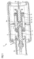
- a feedthrough electrode 4 includes a multi-contact connection assembly 10.
- the multi-contact connection assembly 10 has a first socket 9 and a second socket 11, which are spaced by means of respective support members 14, 15 and intermediate spacer elements 12 relative to each other. Furthermore, corresponding to the flanges as support members 14, 15 corresponding current bands 5a, 5b, 5c are mounted, which ensure a secure electrical connection. Also, the current bands are guided by a guide 13 relative to the sockets 9 and 11. In the sockets 9, 11 (not shown) on the side of the electrical component, a first locking pin 7 is inserted, which must have an electrical connection to the electrical component (not shown).
- a tube electrode 6 has a corresponding second locking pin 8, which in the second socket 11 of the multi-contact connection arrangement 10 is inserted.
- a secure electrical connection is ensured.
- a relative positioning of the first plug pin 7 relative to the second plug pin 8 by means of the multi-contact connection arrangement 10 can be ensured.
- the multicontact connection arrangement 10 is in the example shown Fig. 1 also arranged within the lead-through electrode 4 by means of the holder.
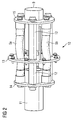
- Fig. 1 shows a perspective side view of the multi-contact connection assembly 10.
- the first socket 9 is shown, the spacer elements 12 has a defined distance from the second socket 11.
- the sockets 9, 11 are electrically connected to each other by means of the current bands 5a, 5b.
- the Fig. 1 shows a perspective side view of the multi-contact connection assembly 10.
- the sockets 9, 11 each corresponding flanges 14, 15, which serve to hold the current bands 5a, 5b and the spacer elements 12.
- a compensation in the horizontal direction of the locking pins 7, 8 (also not shown) is possible by further insertion or removal of the locking pins 7, 8 within the sockets 9, 11 of the multi-contact connection assembly 10.
- a radial displaceability of the sockets 9, 11 are possible by flexible material properties of the spacer elements 12 and design of the attachment and the spacer elements.
- the corresponding current bands 5a, 5b are also radially deflected in this case, due to the larger-sized length compared to the current bands 5a, 5b to the spacer elements 12, the current bands 5a, 5b are deflected and subject to no mechanical stress.
Landscapes
- Engineering & Computer Science (AREA)
- Power Engineering (AREA)
- Details Of Connecting Devices For Male And Female Coupling (AREA)
- Connector Housings Or Holding Contact Members (AREA)
- Transformers For Measuring Instruments (AREA)
- Insulating Bodies (AREA)
Description
- Die Erfindung betrifft eine Multikontaktverbindungsanordnung zur elektrischen Verbindung eines elektrischen Bauteils mit einem elektrischen Anschluss, einer einen erste Steckbuchse und einer zweiten Steckbuchse entlang einer Längsachse zueinander ausgerichtet sind, wobei die Steckbuchsen mittels eines Strombandes miteinander elektrisch verbindbar sind, wobei in die erste Steckbuchse ein erster Steckbolzen und in die zweite Steckbuchse ein zweiter Steckbolzen einschiebbar und der erste Steckbolzen mit dem ersten elektrischen Anschluss elektrisch verbindbar ist, wobei Halterungselemente vorgesehen sind, die zum axialen gegeneinander Verschieben und Positionieren der Steckbuchsen eingerichtet sind.
- Die Erfindung betrifft ferner ein Leitführungssystem mit einer solchen Multikontaktanordnung.
- Eine solche Multikontaktanordnung ist aus der
JP 59 036 909 A - Die
DE 27 46 566 A1 beschreibt eine Durchführung, die über Bandleiter mit den Aktivteilen eines Transformators verbunden ist. Elektrische Hochspannungsverbindungen von elektrischen Bauteilen, beispielsweise Hochspannungstransformatoren, Leistungsschalter oder Drosseln, müssen eine Vielzahl von mechanischen und elektrischen Anforderungen erfüllen. So muss beispielsweise die Verbindung- und Kontaktstelle des elektrischen Bauteils mit einem äußeren elektrischen Energieversorgungsnetz eine umfangreiche Isolation aufweisen. Im Falle von Hoch- beziehungsweise Höchstspannungsanwendungen, beispielsweise 800 kV HGÜ-Transformatoren, sind hierfür umfangreiche Barrierensysteme notwendig. - So beschreibt beispielsweise die
EP 0 285 895 A1 eine Hochspannungsisolationsanordnung für Transformatoren und Drosselspulen. Gemäß der dortigen Erfindung sind zur Anpassung der Gleichspannungsfelder an das elektrische Spannungsfeld Feststoffbarrieren aus Pressspan mit gegenüber gewöhnlichem Pressspann abgestuften erhöhten elektrischen Leitfähigkeiten aufgebaut. - Des Weiteren beschreibt die
DE 10 2005 021 255 B4 ein Barrierensystem für die Leitungsdurchführung einer elektrischen Anlage mit nebeneinander angeordneten Wandelementen als Barrieren, die eine axiale Längserstreckung aufweisen und in Abständen zueinander angeordnet sind. Die so gebildeten Abstände bilden Zwischenräume und somit Kanäle. Ein einstückiges Steckelement bildet eine Auflage, mit dem die Wandelemente verbindbar sind, wobei das einstückige Steckelement von der Leitungsdurchführung räumlich beabstandet ist und die Auflage nahezu parallel zueinander angeordnete Wandelemente mechanisch verbindet, wobei die Halterung und die Fixierung der Wandelemente derart ausgebildet ist, dass die Stirnfläche und zumindest eine Seitenfläche der jeweiligen Wandelemente auf der Auflage aufliegen. - Nachteilig an den bisherigen Leitungsführungssystemen im Stand der Technik für Hochspannungsanwendungen ist, dass die bisherige Stromverbindung mittels einer Durchführungselektrode mit Hilfe von Strombändern dergestalt erfolgt, dass die mit der Durchführungselektrode verbundenen Strombänder mit einer Rohrelektrode verbunden werden. Zur Montage der Durchführung werden daher die Strombänder aus der Elektrode bis an einen zugänglichen Montageort herausgezogen und mittels eines Klemmstückes an ölseitigen Durchführungsbolzen angeschlossen. Anschließend wird die Durchführung zurück in die Elektrode eingeschoben, so dass sich die Strombänder in der Elektrode sammeln. Abhängig von der Stromstärke und damit der notwendigen Anzahl von Strombändern und der axialen Länge des Barrierenaufbaus oberhalb der Elektrode muss in sofern das Aufnahmevolumen im Elektrodeninneren der Durchführungselektrode groß genug zur Aufnahme aller Strombänder sein. Nachteilig ist insbesondere bei einer weit aus der Senkrechten neigenden Durchführung, dass die Strombänder beim Hineinführen in die Durchführungselektrode unerwünscht außerhalb der Elektrode liegen bleiben können und es zu entsprechenden elektrischen Fehlern in Form von elektrischen Durchschlägen oder elektrischen Teilentladungen kommen kann. Aufgrund der engen baulichen Abmessungen der Rohrelektrode und der Durchführungselektrode sind beim Einziehen der Rohrelektrode in die Durchführungselektrode keine Zugänglichkeit und auch keine Sichtkontrolle über die korrekte Lage der Elektroden und der Strombänder gegeben. Insofern kann eine letztendliche genaue Positionierung nur mit zusätzlichen äußeren Hilfsmitteln gewährleistet werden.
- Die eingangs genannte Multikontaktverbindungsanordnung weist den Nachteil auf, dass hohe Anforderungen an die Positionierung der miteinander zu verbindenden Bauteile gestellt werden.
- Aufgabe der vorliegenden Erfindung ist es daher, eine Multikontaktverbindungsanordnung der eingangs genannten Art bereitzustellen, die eine einfache und sichere Montage der elektrischen Verbindung ermöglicht.
- Gelöst wird die Aufgabe dadurch, dass der radiale Abstand der Steckbuchsen relativ zueinander mittels Distanzelemente einstellbar ist, wobei die Distanzelemente und das Stromband mit einem ersten Flansch der ersten Steckbuchse und einem zweiten Flansch der zweiten Steckbuchse verbindbar sind.
- Erfindungsgemäß ist eine Multikontaktverbindungsanordnung vorgesehen, bei welcher der erste elektrische Anschluss mit einem ersten Steckbolzen und die Rohrelektrode mit einem zweiten Steckbolzen elektrisch verbindbar sind und der erste Steckbolzen in eine erste Steckbuchse und der zweite Steckbolzen in eine zweite Steckbuchse einsteckbar ist, wobei die Steckbuchsen mit einem Stromband elektrisch verbindbar sind. Hierdurch wird vorteilhafterweise das feste Verbinden der Enden der Strombänder mit der Rohrelektrode und der Durchführungselektrode vermieden. Die genaue Lage der entsprechenden Steckbolzen in den Steckbuchsen kann eine elektrische Verbindung gewährleisten. Des Weiteren ist es gerade im Rahmen der Fertigung und Montage des Leitungsführungssystems mit der vorliegenden Erfindung möglich, die entsprechenden Baugruppen des Leitungsführungssystems, insbesondere die elektrischen Anschlüsse, einfach, schnell und sicher miteinander zu verbinden.
- In einer vorteilhaften Ausgestaltung des Leitungsführungssystems ist vorgesehen, dass die Steckbuchsen der Multikontaktverbindungsanordnung bezogen auf die Längsachse der Durchführungselektrode axial und/oder radial verschiebbar sind. Durch die Möglichkeit der relativen Verschiebung der Steckbuchsen der Multikontaktverbindungsanordnung ist es möglich, während des Montageverfahrens auch bei abweichenden Ausrichtungen der Steckbolzen relativ zueinander eine sichere mechanische Verbindung und damit eine sichere elektrische Verbindung zu gewährleisten. Selbst bei abweichenden Positionen der Steckbolzen relativ zur Längsachse der Durchführungselektrode kann mittels der gegeneinander verschiebbaren Steckbuchsen der Multikontaktverbindungsanordnung eine sichere elektrische Verbindung gewährleistet werden.
- Durch die weiterhin vorteilhafterweise flexible Befestigung der Multikontaktverbindungsanordnung innerhalb der Durchführungselektrode ist eine einfache und elektrisch sichere Positionierung der Steckbuchsen und der damit verbundenen Rohrelektrode auf der einen Seite der Durchführungselektrode sowie des elektrischen Anschlusses zum elektrischen Bauteil, beispielsweise einem Hochspannungstransformator, gegeben. Zusätzlich kann durch die Einschubtiefe der Steckbolzen in die jeweilige Steckbuchse der axiale Abstand der Steckbolzen und damit der entsprechenden jeweils zugeordneten elektrischen Anschlüsse gesteuert werden. Durch die flexible Halterung der Multikontaktverbindungsanordnung innerhalb der Durchführungselektrode kann somit zum Einen entweder die gesamte Anordnung flexibel innerhalb der Durchführungselektrode verschoben werden.
- Andererseits ist bei nur sehr geringen Fertigungsunterschieden eine relative Verschiebung der Steckbuchsen relativ zueinander bei fester Multikontaktverbindungsanordnung innerhalb der Durchführungselektrode gewährleistet. Die Multikontaktverbindungsanordnung kann insofern auf einem Schlitten innerhalb der Durchführungselektrode angeordnet werden.
- Auch ist es möglich, die Multikontaktverbindungsanordnung mit flexiblen Halteelementen, beispielsweise mittels isolierender Federn innerhalb der Durchführungselektrode anzuordnen und somit in Gänze eine flexible Verschiebbarkeit in radialer und/oder axialer Richtung bezogen auf die Längsachse der Durchführungselektrode zu gewährleisten. Auch die Verwendung von Kunststoffelementen mit elastischen Eigenschaften zur Halterung der Multikontaktverbindungsanordnung innerhalb der Durchführungselektrode gewährleistet eine mögliche flexible Aufhängung der vorgenannten Multikontaktverbindungsanordnung innerhalb der Durchführungselektrode.
- Es wird als vorteilhaft angesehen, dass der radiale Abstand der Steckbuchsen bezogen auf die Längsachse der Multikontaktverbindungsanordnung mittels arretierbarer Distanzelemente vorgebbar ist. Hierdurch besteht die Möglichkeit, die Multikontaktverbindungsanordnung für den jeweils notwendigen Verbindungsanwendungsfall so zu konzipieren, dass bei unterschiedlichen Netz- und Bauteilgegebenheiten die standardisierte Multikontaktverbindungsanordnung bezogen auf den radialen Abstand lediglich bezüglich der Distanzelemente anzupassen ist. Hierdurch ist eine standardisierte Fertigung der Multikontaktverbindungsanordnung, insbesondere der Steckbuchsen zueinander möglich, so dass in Abhängigkeit von der jeweiligen elektrischen Stromstärke die Distanz zwischen den Steckbuchsen mittels der Distanzelemente einstellbar ist. Insbesondere die Steckbuchsen und Steckbolzen können für unterschiedliche Stromstärken genutzt werden. Lediglich die Zahl der Strombänder in der Multikontaktanordnung ist auf die jeweiligen Stromstärken abzustimmen.
- Vorteilhafterweise sind die Distanzelemente innerhalb der Multikontaktverbindungsanordnung verschraubbar. Aufgrund der axialen und/oder radialen Verschiebbarkeit der Steckbuchsen relativ zueinander ist vorteilhafterweise das Stromband mittels einer Führung zumindest teilweise relativ zu mindestens einer der Steckbuchsen der Multikontaktverbindungsanordnung geführt. Vorteilhafterweise wird hierdurch gewährleistet, dass die Strombänder relativ zu den Steckbuchsen geführt sind und somit auch bei einer insbesondere radialen Verschiebung relativ zueinander der Steckbuchsen es nicht zu unerwünschten elektrischen Beeinträchtigungen, beispielsweise elektrische Übergänge aufgrund veränderter Isolationsabstände, kommt. In Abhängigkeit der zu verwendenden elektrischen Anforderungen innerhalb des elektrischen Bauteils und/oder des entsprechenden Energieversorgungsnetzes sind mehrere Strombänder äquidistant bezogen auf die Steckbuchsen relativ zueinander angeordnet. Hierdurch liegen die Elektrode und das innere stromführende Teil auf einem Potential. Gleichzeitig sind diese Bauteile lediglich an einer Stelle miteinander verbunden, so dass zusätzliche interne Stromkreise vermieden werden.
- Erfindungsgemäß ist eine Multikontaktverbindungsanordnung bereitgestellt, deren zwei Steckbuchsen entlang einer Längsachse zueinander ausgerichtet sind und die Steckbuchsen mittels eines Strombandes miteinander elektrisch verbindbar sind und in die Steckbuchsen jeweils ein Steckbolzen einschiebbar und ein Steckbolzen mit dem elektrischen Anschluss elektrisch verbindbar ist. Im Vergleich zu einer festen Befestigung eines Strombandes an dem elektrischen Bauteil, insbesondere einem Hochspannungsgleichstromtransformator, und einer Rohrelektrode bezogen auf das umgebende Energieversorgungsnetz bietet die vorgenannte Multikontaktverbindungsanordnung den Vorteil, dass die einzelnen Baugruppen zur elektrischen Verbindung mittels der Multikontaktverbindungsanordnung mechanisch einfach und elektrisch sicher verbunden werden können.
- Der radiale Abstand der Steckbuchsen ist erfindungsgemäß relativ zueinander mittels Distanzelementen einstellbar. Die Steckbuchsen sind axial gegeneinander verschiebbar und positionierbar, wobei ein entsprechendes Halteelement eine Positionier- beziehungsweise Verschiebbarkeit gewährleistet. Ins besondere die Verwendung eines ersten Flansches bezogen auf die erste Steckbuchse und eines zweiten Flansches bezogen auf die zweite Steckbuchse, mittels derer die Distanzelemente und/oder die Strombänder befestigt werden können, bietet den Vorteil, dass die Multikontaktverbindungsanordnung ausschließlich eine elektrische Verbindung des elektrischen Bauteils mit dem umgebenden Energieversorgungsnetz gewährleisten muss. Eine entsprechende mechanische Positionierung und Ausrichtung der Durchführungselektrode relativ zur Rohrelektrode kann mittels der vorgenannten Multikontaktverbindungsanordnung ebenfalls schnell und einfach bereitgestellt werden. Die relative Verschiebbarkeit der Steckbuchsen gegeneinander gewährleistet, dass die jeweiligen Steckbolzen als Verbindungsstücke zu den jeweiligen elektrischen Anschlüssen schnell und einfach, sowie mechanisch stabil und sicher positioniert und befestigt werden können.
- Mehrere Strombänder sind vorteilhafterweise dergestalt angepasst, dass in Abhängigkeit der erwarteten Strombelastung der Querschnitt, die Anzahl und die Materialeigenschaft der Strombänder entsprechend dimensioniert werden.
- Weitere vorteilhafte Ausgestaltungen ergeben sich aus den Unteransprüchen. Die Erfindung wird anhand der nachfolgenden Figuren näher erläutert. Es zeigen:
- Fig. 1
- eine perspektivische Schnittansicht der Durchführungselektrode mit innen liegender Multikontaktverbindungsanordnung;
- Fig. 2
- eine perspektivische Seitenansicht der Multikontaktverbindungsanordnung.
- Die
Fig. 1 zeigt eine perspektivische Schnittzeichnung des erfindungsgemäßen Leitungsführungssystems 1. Eine Durchführungselektrode 4 beinhaltet eine Multikontaktverbindungsanordnung 10. Die Multikontaktverbindungsanordnung 10 weist dabei einen erste Steckbuchse 9 und eine zweiten Steckbuchse 11 auf, die mittels entsprechender Halterungselemente 14, 15 und zwischenliegenden Distanzelementen 12 relativ zueinander beabstandet sind. Des Weiteren sind über die Flansche als Halterungselemente 14, 15 entsprechende Strombänder 5a, 5b, 5c angebracht, die eine sichere elektrische Verbindung gewährleisten. Ebenfalls sind die Strombänder durch eine Führung 13 relativ zu den Steckbuchsen 9 und 11 geführt. In die Steckbuchsen 9, 11 sind auf Seiten des elektrischen Bauteils (nicht dargestellt) ein erster Steckbolzen 7 eingeführt, der eine elektrische Weiterverbindung zum elektrischen Bauteil aufweisen muss (nicht dargestellt). Eine Rohrelektrode 6 weist einen entsprechenden zweiten Steckbolzen 8 auf, der in die zweite Steckbuchse 11 der Multikontaktverbindungsanordnung 10 einsteckbar ist. Beim vollständigen Einschub der Steckbolzen 7, 8 in die Steckbuchsen 9, 11 der Multikontaktverbindungsanordnung 10 ist eine sichere elektrische Verbindung gewährleistet. Gleichzeitig kann eine relative Positionierung des ersten Steckbolzens 7 relativ zum zweiten Steckbolzen 8 mittels der Multikontaktverbindungsanordnung 10 gewährleistet werden. Die Multikontaktverbindungsanordnung 10 ist im gezeigten Beispiel derFig. 1 mittels der Halterung ebenfalls innerhalb der Durchführungselektrode 4 angeordnet. - Neben der im Beispiel der
Fig. 1 gezeigten starren Befestigung der Multikontaktverbindungsanordnung 10 innerhalb der Durchführungselektrode 4 ist ebenfalls eine flexible Halterung und Aufhängung der Multikontaktverbindungsanordnung 10 innerhalb der Durchführungselektrode 4 möglich. Die Durchführungselektrode 4 und die Rohrelektrode 6 liegen auf gleichem Spannungspotential, so dass zusätzliche interne Stromkreise verhindert werden.
DieFig. 2 zeigt eine perspektivische Seitenansicht der Multikontaktverbindungsanordnung 10. Auf der einen Seite ist die erste Steckbuchse 9 dargestellt, die Distanzelemente 12 einen definierten Abstand zur zweiten Steckbuchse 11 aufweist. Die Steckbuchsen 9, 11 sind mittels der Strombänder 5a, 5b miteinander elektrisch verbunden. Im gezeigten Beispiel derFig. 2 weisen die Steckbuchsen 9, 11 die jeweils entsprechende Flansche 14, 15 auf, die zur Halterung der Strombänder 5a, 5b sowie der Distanzelemente 12 dienen. Ein Ausgleich in horizontaler Richtung der Steckbolzen 7, 8 (auch nicht dargestellt) ist durch ein weiteres Ein- beziehungsweise Ausschieben der Steckbolzen 7, 8 innerhalb der Steckbuchsen 9, 11 der Multikontaktverbindungsanordnung 10 möglich. Eine radiale Verschiebbarkeit der Steckbuchsen 9, 11 sind durch flexible Materialeigenschaften der Distanzelemente 12 und Ausgestaltung der Befestigung und der Distanzelemente möglich. Die entsprechenden Strombänder 5a, 5b werden in diesem Falle ebenfalls radial ausgelenkt, wobei aufgrund der größer dimensionierten Länge im Vergleich der Strombänder 5a, 5b zu den Distanzelementen 12 die Strombänder 5a, 5b ausgelenkt werden und keiner mechanischen Belastung dabei unterliegen.
Claims (12)
- Multikontaktverbindungsanordnung (10) zur elektrischen Verbindung eines elektrischen Bauteils mit einem elektrischen Anschluss (3a), einer einen erste Steckbuchse (9) und einer zweiten Steckbuchse (11) entlang einer Längsachse zueinander ausgerichtet sind, wobei die Steckbuchsen (9,11) mittels eines Strombandes (5a,5b,5c) miteinander elektrisch verbindbar sind, wobei in die erste Steckbuchse (9) ein erster Steckbolzen (7) und in die zweite Steckbuchse (11) ein zweiter Steckbolzen (8) einschiebbar und der erste Steckbolzen (7) mit dem ersten elektrischen Anschluss (3a) elektrisch verbindbar ist, wobei
Halterungselemente (14,15) vorgesehen sind, die zum axialen gegeneinander Verschieben und Positionieren der Steckbuchsen (9,11) eingerichtet sind,
dadurch gekennzeichnet, dass der radiale Abstand der Steckbuchsen (9,11) relativ zueinander mittels Distanzelemente (12) einstellbar ist, wobei die Distanzelemente (12) und das Stromband (5a,5b,5c) mit einem ersten Flansch (14) der ersten Steckbuchse (9) und einem zweiten Flansch (15) der zweiten Steckbuchse (11) verbindbar sind. - Multikontaktverbindungsanordnung (10) nach Anspruch 1,
dadurch gekennzeichnet, dass
das Stromband (5a,5b,5c) mittels einer Führung (13) zumindest teilweise entlang der Längsachse führbar ist. - Multikontaktverbindungsanordnung (10) nach einem der vorhergehenden Ansprüche,
dadurch gekennzeichnet, dass mehrere Strombänder (5a,5b,5c) in Abhängigkeit der erwarteten Strombelastung bezüglich des Querschnitts und der Materialeigenschaften angepasst sind. - Leitungsführungssystem (1) mit einer Multikontaktverbindungsanordnung (10) nach einem der Ansprüche 1 bis 3, wobei ein erster elektrischer Anschluss (3a) des elektrischen Bauteils in einer Durchführungselektrode (4) mit einem zweiten elektrischen Anschluss (3b) über ein Stromband (5a,5b,5c) und eine Rohrelektrode (6) verbindbar ist, und wobei der erste elektrische Anschluss (3a) mit dem ersten Steckbolzen (7) und die Rohrelektrode (6) mit dem zweiten Steckbolzen (8) der Multikontaktverbindungsanordnung (10) elektrisch verbindbar ist.
- Leitungsführungssystem (1) nach Anspruch 4,
dadurch gekennzeichnet, dass die Steckbuchsen (9,11) der Multikontaktverbindungsanordnung (10) bezogen auf die Längsachse der Durchführungselektrode (4) axial und/oder radial verschiebbar sind. - Leitungsführungssystem (1) nach einem der Ansprüche 4 oder 5,
dadurch gekennzeichnet, dass die Multikontaktverbindungsanordnung (10) innerhalb der Durchführungselektrode (4) flexibel befestigt ist. - Leitungsführungssystem (1) nach einem der Ansprüche 4 bis 6,
dadurch gekennzeichnet, dass der radiale Abstand der Steckbuchsen (9,11) bezogen auf die Längsachse der Multikontaktverbindungsanordnung (10) mittels arretierbarer Distanzelemente (12) vorgebbar ist. - Leitungsführungssystem (1) nach einem der Ansprüche 4 bis 7,
dadurch gekennzeichnet, dass
das Stromband (5a,5b,5c) mittels einer Führung (13) zumindest teilweise relativ zu zumindest eine der Steckbuchsen (9,11) der Multikontaktverbindungsanordnung (10) geführt sind. - Leitungsführungssystem (1) nach einem der Ansprüche 4 bis 8,
dadurch gekennzeichnet, dass
mehrere Strombänder (5a,5b,5c) äquidistant bezogen auf die Steckbuchsen (9,11) angeordnet sind. - Leitungsführungssystem (1) nach einem der Ansprüche 4 bis 9,
dadurch gekennzeichnet, dass
das elektrische Bauteil ein Transformator, eine Drossel oder eine Spule ist. - Leitungsführungssystem (1) nach einem der Ansprüche 4 bis 10,
dadurch gekennzeichnet, dass
die Durchführungselektrode (4) und die Rohrelektrode (6) gegeneinander elektrisch isoliert sind. - Leitungsführungssystem (1) nach einem der Ansprüche 4 bis 11,
dadurch gekennzeichnet, dass
die Durchführungselektrode (4), die Rohrelektrode (6) und die Multikontaktverbindungsanordnung (10) aufgrund der Anordnung der Strombänder (5a,5b,5c) das gleiche Spannungspotential besitzen.
Applications Claiming Priority (1)
| Application Number | Priority Date | Filing Date | Title |
|---|---|---|---|
| PCT/EP2010/053391 WO2011113479A1 (de) | 2010-03-16 | 2010-03-16 | Leitungsführungssystem für einen hochspannungstransformator |
Publications (2)
| Publication Number | Publication Date |
|---|---|
| EP2548209A1 EP2548209A1 (de) | 2013-01-23 |
| EP2548209B1 true EP2548209B1 (de) | 2016-11-16 |
Family
ID=43302008
Family Applications (1)
| Application Number | Title | Priority Date | Filing Date |
|---|---|---|---|
| EP10712383.8A Active EP2548209B1 (de) | 2010-03-16 | 2010-03-16 | Leitungsführungssystem für einen hochspannungstransformator |
Country Status (4)
| Country | Link |
|---|---|
| EP (1) | EP2548209B1 (de) |
| CN (1) | CN103109332B (de) |
| BR (1) | BR112012023429B1 (de) |
| WO (1) | WO2011113479A1 (de) |
Families Citing this family (2)
| Publication number | Priority date | Publication date | Assignee | Title |
|---|---|---|---|---|
| DE102016209132A1 (de) * | 2016-05-25 | 2017-11-30 | Siemens Aktiengesellschaft | Vorrichtung zum Verbinden eines Hochspannungsleiters mit einer Wicklung eines elektrischen Geräts |
| DE102017204031A1 (de) | 2017-03-10 | 2018-09-13 | Siemens Aktiengesellschaft | Elektrische Kontaktanordnung |
Family Cites Families (7)
| Publication number | Priority date | Publication date | Assignee | Title |
|---|---|---|---|---|
| FR1393509A (fr) * | 1964-02-12 | 1965-03-26 | Materiel Electrique S W Le | Traversée isolante sons forte intensité pour appareil électrique |
| DE2746566C3 (de) * | 1977-10-17 | 1981-11-26 | Transformatoren Union Ag, 7000 Stuttgart | Hochspannungsdurchführung zum Anschluß von mit Isolierflüssigkeit gefüllten Transformatoren an SF↓6↓-isolierte Kabel oder Schaltanlagen |
| JPS5745909A (en) * | 1980-09-04 | 1982-03-16 | Hitachi Ltd | Split type stationary induction device |
| JPS5936909A (ja) * | 1982-04-05 | 1984-02-29 | Hitachi Ltd | 静止誘導電器の接続装置 |
| ATE73572T1 (de) | 1987-04-09 | 1992-03-15 | Siemens Ag | Hochspannungsisolationsanordnung fuer transformatoren und drosselspulen, insbesondere zur hochspannungs-gleichstrom-uebertragung (hgue). |
| DE102005021255B4 (de) | 2005-05-02 | 2007-08-16 | Siemens Ag | Barrierensystem für die Leitungsdurchführung einer elektrischen Anlage |
| CN2847598Y (zh) * | 2005-11-22 | 2006-12-13 | 宋建龙 | 动力电缆连接器 |
-
2010
- 2010-03-16 EP EP10712383.8A patent/EP2548209B1/de active Active
- 2010-03-16 WO PCT/EP2010/053391 patent/WO2011113479A1/de not_active Ceased
- 2010-03-16 BR BR112012023429-3A patent/BR112012023429B1/pt not_active IP Right Cessation
- 2010-03-16 CN CN201080065482.9A patent/CN103109332B/zh active Active
Also Published As
| Publication number | Publication date |
|---|---|
| EP2548209A1 (de) | 2013-01-23 |
| BR112012023429B1 (pt) | 2019-07-09 |
| CN103109332B (zh) | 2016-11-02 |
| CN103109332A (zh) | 2013-05-15 |
| BR112012023429A2 (pt) | 2017-10-24 |
| WO2011113479A1 (de) | 2011-09-22 |
Similar Documents
| Publication | Publication Date | Title |
|---|---|---|
| EP2589116B1 (de) | Drehbarer steckverbinder | |
| EP3685471B1 (de) | Hochstromsteckverbinder mit isolierhülse | |
| EP1997117B1 (de) | Verbindungselement für eine elektrische abschirmungsanordnung | |
| EP2374186B1 (de) | Elektrische anschlussklemme zur durchführung einer leitung durch eine wandung | |
| DE102023104652A1 (de) | Berührungsschutzabdeckung, Anschlussteil und Modulverbinder | |
| EP2047571A1 (de) | Steckverbinder für die telekommunikations- und datentechnik | |
| EP4089854B1 (de) | Kontakteinrichtung für eine doppelstromschiene, gegenstück zu der kontakteinrichtung und kontaktsystem für zwei doppelstromschienen | |
| DE102023110642A1 (de) | Steckverbindungssystem und elektrifiziertes kraftfahrzeug mit einem solchen steckverbindungssystem | |
| EP4189779B1 (de) | Leiteranschlussklemme, verwendung und verfahren zur montage einer leiteranschlussklemme | |
| DE102009017541A1 (de) | Feder-Steckklemme | |
| EP2846336B1 (de) | Verbindung von mindestens vier elektrischen Leitern | |
| WO2011113479A1 (de) | Leitungsführungssystem für einen hochspannungstransformator | |
| EP3474024A1 (de) | Stromwandler mit fluid- oder ölpapierisolierung für hochspannung | |
| DE102021200312A1 (de) | Kontaktieranordnung und entsprechendes Kontaktierverfahren | |
| DE102010022024A1 (de) | Energieversorgungsvorrichtung mit kompaktem Hochspannungsanschluss | |
| DE102005021255B4 (de) | Barrierensystem für die Leitungsdurchführung einer elektrischen Anlage | |
| DE102006038221B4 (de) | Vorrichtung zur elektrischen Abschirmung einer Hochspannungsdurchführung | |
| DE102018201160A1 (de) | Hochspannungsdurchführung, elektrisches Gerät mit Hochspannungsdurchführung und Verfahren zur Herstellung des elektrischen Gerätes | |
| AT17394U1 (de) | Kabelanordnung mit gehäuse | |
| WO2021229469A1 (de) | Steckerbuchse für wasserdichte anwendungen | |
| DE202008009101U1 (de) | Messwertgeber-Anordnung zur Kurzschlusserfassung in elektrischen Mittelspannungs-Schaltanlagen | |
| EP3076409B1 (de) | Elektrische verbindung voneinander beabstandeter wicklungen | |
| DE102013005340A1 (de) | Elektrische Verbindung mit kapazitiver Kopplung | |
| EP3665710B1 (de) | Anordnung zum anschluss an ein hochspannungsnetz mit mehreren einphasigen transformatoren | |
| EP2351056A1 (de) | Barrierenanordnung für eine leitungsdurchführung |
Legal Events
| Date | Code | Title | Description |
|---|---|---|---|
| PUAI | Public reference made under article 153(3) epc to a published international application that has entered the european phase |
Free format text: ORIGINAL CODE: 0009012 |
|
| 17P | Request for examination filed |
Effective date: 20120817 |
|
| AK | Designated contracting states |
Kind code of ref document: A1 Designated state(s): AT BE BG CH CY CZ DE DK EE ES FI FR GB GR HR HU IE IS IT LI LT LU LV MC MK MT NL NO PL PT RO SE SI SK SM TR |
|
| RAP1 | Party data changed (applicant data changed or rights of an application transferred) |
Owner name: SIEMENS AKTIENGESELLSCHAFT |
|
| DAX | Request for extension of the european patent (deleted) | ||
| 17Q | First examination report despatched |
Effective date: 20150720 |
|
| GRAP | Despatch of communication of intention to grant a patent |
Free format text: ORIGINAL CODE: EPIDOSNIGR1 |
|
| INTG | Intention to grant announced |
Effective date: 20160610 |
|
| GRAS | Grant fee paid |
Free format text: ORIGINAL CODE: EPIDOSNIGR3 |
|
| GRAA | (expected) grant |
Free format text: ORIGINAL CODE: 0009210 |
|
| AK | Designated contracting states |
Kind code of ref document: B1 Designated state(s): AT BE BG CH CY CZ DE DK EE ES FI FR GB GR HR HU IE IS IT LI LT LU LV MC MK MT NL NO PL PT RO SE SI SK SM TR |
|
| REG | Reference to a national code |
Ref country code: GB Ref legal event code: FG4D Free format text: NOT ENGLISH |
|
| REG | Reference to a national code |
Ref country code: CH Ref legal event code: EP |
|
| REG | Reference to a national code |
Ref country code: IE Ref legal event code: FG4D Free format text: LANGUAGE OF EP DOCUMENT: GERMAN |
|
| REG | Reference to a national code |
Ref country code: AT Ref legal event code: REF Ref document number: 846597 Country of ref document: AT Kind code of ref document: T Effective date: 20161215 |
|
| REG | Reference to a national code |
Ref country code: DE Ref legal event code: R096 Ref document number: 502010012729 Country of ref document: DE |
|
| PG25 | Lapsed in a contracting state [announced via postgrant information from national office to epo] |
Ref country code: LV Free format text: LAPSE BECAUSE OF FAILURE TO SUBMIT A TRANSLATION OF THE DESCRIPTION OR TO PAY THE FEE WITHIN THE PRESCRIBED TIME-LIMIT Effective date: 20161116 |
|
| REG | Reference to a national code |
Ref country code: SE Ref legal event code: TRGR |
|
| REG | Reference to a national code |
Ref country code: NL Ref legal event code: MP Effective date: 20161116 |
|
| REG | Reference to a national code |
Ref country code: LT Ref legal event code: MG4D |
|
| PG25 | Lapsed in a contracting state [announced via postgrant information from national office to epo] |
Ref country code: LT Free format text: LAPSE BECAUSE OF FAILURE TO SUBMIT A TRANSLATION OF THE DESCRIPTION OR TO PAY THE FEE WITHIN THE PRESCRIBED TIME-LIMIT Effective date: 20161116 Ref country code: NO Free format text: LAPSE BECAUSE OF FAILURE TO SUBMIT A TRANSLATION OF THE DESCRIPTION OR TO PAY THE FEE WITHIN THE PRESCRIBED TIME-LIMIT Effective date: 20170216 Ref country code: NL Free format text: LAPSE BECAUSE OF FAILURE TO SUBMIT A TRANSLATION OF THE DESCRIPTION OR TO PAY THE FEE WITHIN THE PRESCRIBED TIME-LIMIT Effective date: 20161116 Ref country code: GR Free format text: LAPSE BECAUSE OF FAILURE TO SUBMIT A TRANSLATION OF THE DESCRIPTION OR TO PAY THE FEE WITHIN THE PRESCRIBED TIME-LIMIT Effective date: 20170217 |
|
| PG25 | Lapsed in a contracting state [announced via postgrant information from national office to epo] |
Ref country code: PL Free format text: LAPSE BECAUSE OF FAILURE TO SUBMIT A TRANSLATION OF THE DESCRIPTION OR TO PAY THE FEE WITHIN THE PRESCRIBED TIME-LIMIT Effective date: 20161116 Ref country code: ES Free format text: LAPSE BECAUSE OF FAILURE TO SUBMIT A TRANSLATION OF THE DESCRIPTION OR TO PAY THE FEE WITHIN THE PRESCRIBED TIME-LIMIT Effective date: 20161116 Ref country code: HR Free format text: LAPSE BECAUSE OF FAILURE TO SUBMIT A TRANSLATION OF THE DESCRIPTION OR TO PAY THE FEE WITHIN THE PRESCRIBED TIME-LIMIT Effective date: 20161116 Ref country code: PT Free format text: LAPSE BECAUSE OF FAILURE TO SUBMIT A TRANSLATION OF THE DESCRIPTION OR TO PAY THE FEE WITHIN THE PRESCRIBED TIME-LIMIT Effective date: 20170316 Ref country code: FI Free format text: LAPSE BECAUSE OF FAILURE TO SUBMIT A TRANSLATION OF THE DESCRIPTION OR TO PAY THE FEE WITHIN THE PRESCRIBED TIME-LIMIT Effective date: 20161116 |
|
| PG25 | Lapsed in a contracting state [announced via postgrant information from national office to epo] |
Ref country code: EE Free format text: LAPSE BECAUSE OF FAILURE TO SUBMIT A TRANSLATION OF THE DESCRIPTION OR TO PAY THE FEE WITHIN THE PRESCRIBED TIME-LIMIT Effective date: 20161116 Ref country code: CZ Free format text: LAPSE BECAUSE OF FAILURE TO SUBMIT A TRANSLATION OF THE DESCRIPTION OR TO PAY THE FEE WITHIN THE PRESCRIBED TIME-LIMIT Effective date: 20161116 Ref country code: DK Free format text: LAPSE BECAUSE OF FAILURE TO SUBMIT A TRANSLATION OF THE DESCRIPTION OR TO PAY THE FEE WITHIN THE PRESCRIBED TIME-LIMIT Effective date: 20161116 Ref country code: RO Free format text: LAPSE BECAUSE OF FAILURE TO SUBMIT A TRANSLATION OF THE DESCRIPTION OR TO PAY THE FEE WITHIN THE PRESCRIBED TIME-LIMIT Effective date: 20161116 Ref country code: SK Free format text: LAPSE BECAUSE OF FAILURE TO SUBMIT A TRANSLATION OF THE DESCRIPTION OR TO PAY THE FEE WITHIN THE PRESCRIBED TIME-LIMIT Effective date: 20161116 |
|
| REG | Reference to a national code |
Ref country code: DE Ref legal event code: R097 Ref document number: 502010012729 Country of ref document: DE |
|
| RAP2 | Party data changed (patent owner data changed or rights of a patent transferred) |
Owner name: SIEMENS AKTIENGESELLSCHAFT |
|
| PG25 | Lapsed in a contracting state [announced via postgrant information from national office to epo] |
Ref country code: IT Free format text: LAPSE BECAUSE OF FAILURE TO SUBMIT A TRANSLATION OF THE DESCRIPTION OR TO PAY THE FEE WITHIN THE PRESCRIBED TIME-LIMIT Effective date: 20161116 Ref country code: BG Free format text: LAPSE BECAUSE OF FAILURE TO SUBMIT A TRANSLATION OF THE DESCRIPTION OR TO PAY THE FEE WITHIN THE PRESCRIBED TIME-LIMIT Effective date: 20170216 Ref country code: SM Free format text: LAPSE BECAUSE OF FAILURE TO SUBMIT A TRANSLATION OF THE DESCRIPTION OR TO PAY THE FEE WITHIN THE PRESCRIBED TIME-LIMIT Effective date: 20161116 |
|
| PLBE | No opposition filed within time limit |
Free format text: ORIGINAL CODE: 0009261 |
|
| STAA | Information on the status of an ep patent application or granted ep patent |
Free format text: STATUS: NO OPPOSITION FILED WITHIN TIME LIMIT |
|
| REG | Reference to a national code |
Ref country code: CH Ref legal event code: NV Representative=s name: SIEMENS SCHWEIZ AG, CH Ref country code: CH Ref legal event code: PCOW Free format text: NEW ADDRESS: WERNER-VON-SIEMENS-STRASSE 1, 80333 MUENCHEN (DE) |
|
| 26N | No opposition filed |
Effective date: 20170817 |
|
| REG | Reference to a national code |
Ref country code: CH Ref legal event code: PL |
|
| PG25 | Lapsed in a contracting state [announced via postgrant information from national office to epo] |
Ref country code: MC Free format text: LAPSE BECAUSE OF FAILURE TO SUBMIT A TRANSLATION OF THE DESCRIPTION OR TO PAY THE FEE WITHIN THE PRESCRIBED TIME-LIMIT Effective date: 20161116 Ref country code: SI Free format text: LAPSE BECAUSE OF FAILURE TO SUBMIT A TRANSLATION OF THE DESCRIPTION OR TO PAY THE FEE WITHIN THE PRESCRIBED TIME-LIMIT Effective date: 20161116 |
|
| REG | Reference to a national code |
Ref country code: IE Ref legal event code: MM4A |
|
| REG | Reference to a national code |
Ref country code: FR Ref legal event code: ST Effective date: 20171130 |
|
| PG25 | Lapsed in a contracting state [announced via postgrant information from national office to epo] |
Ref country code: FR Free format text: LAPSE BECAUSE OF NON-PAYMENT OF DUE FEES Effective date: 20170331 Ref country code: LU Free format text: LAPSE BECAUSE OF NON-PAYMENT OF DUE FEES Effective date: 20170316 |
|
| PG25 | Lapsed in a contracting state [announced via postgrant information from national office to epo] |
Ref country code: CH Free format text: LAPSE BECAUSE OF NON-PAYMENT OF DUE FEES Effective date: 20170331 Ref country code: IE Free format text: LAPSE BECAUSE OF NON-PAYMENT OF DUE FEES Effective date: 20170316 Ref country code: LI Free format text: LAPSE BECAUSE OF NON-PAYMENT OF DUE FEES Effective date: 20170331 |
|
| REG | Reference to a national code |
Ref country code: BE Ref legal event code: MM Effective date: 20170331 |
|
| REG | Reference to a national code |
Ref country code: AT Ref legal event code: MM01 Ref document number: 846597 Country of ref document: AT Kind code of ref document: T Effective date: 20170316 |
|
| PG25 | Lapsed in a contracting state [announced via postgrant information from national office to epo] |
Ref country code: BE Free format text: LAPSE BECAUSE OF NON-PAYMENT OF DUE FEES Effective date: 20170331 |
|
| PG25 | Lapsed in a contracting state [announced via postgrant information from national office to epo] |
Ref country code: AT Free format text: LAPSE BECAUSE OF NON-PAYMENT OF DUE FEES Effective date: 20170316 |
|
| PG25 | Lapsed in a contracting state [announced via postgrant information from national office to epo] |
Ref country code: MT Free format text: LAPSE BECAUSE OF FAILURE TO SUBMIT A TRANSLATION OF THE DESCRIPTION OR TO PAY THE FEE WITHIN THE PRESCRIBED TIME-LIMIT Effective date: 20161116 |
|
| PG25 | Lapsed in a contracting state [announced via postgrant information from national office to epo] |
Ref country code: HU Free format text: LAPSE BECAUSE OF FAILURE TO SUBMIT A TRANSLATION OF THE DESCRIPTION OR TO PAY THE FEE WITHIN THE PRESCRIBED TIME-LIMIT; INVALID AB INITIO Effective date: 20100316 |
|
| PG25 | Lapsed in a contracting state [announced via postgrant information from national office to epo] |
Ref country code: CY Free format text: LAPSE BECAUSE OF NON-PAYMENT OF DUE FEES Effective date: 20161116 |
|
| PG25 | Lapsed in a contracting state [announced via postgrant information from national office to epo] |
Ref country code: MK Free format text: LAPSE BECAUSE OF FAILURE TO SUBMIT A TRANSLATION OF THE DESCRIPTION OR TO PAY THE FEE WITHIN THE PRESCRIBED TIME-LIMIT Effective date: 20161116 |
|
| PG25 | Lapsed in a contracting state [announced via postgrant information from national office to epo] |
Ref country code: TR Free format text: LAPSE BECAUSE OF FAILURE TO SUBMIT A TRANSLATION OF THE DESCRIPTION OR TO PAY THE FEE WITHIN THE PRESCRIBED TIME-LIMIT Effective date: 20161116 |
|
| PG25 | Lapsed in a contracting state [announced via postgrant information from national office to epo] |
Ref country code: IS Free format text: LAPSE BECAUSE OF FAILURE TO SUBMIT A TRANSLATION OF THE DESCRIPTION OR TO PAY THE FEE WITHIN THE PRESCRIBED TIME-LIMIT Effective date: 20170316 |
|
| REG | Reference to a national code |
Ref country code: DE Ref legal event code: R081 Ref document number: 502010012729 Country of ref document: DE Owner name: SIEMENS ENERGY GLOBAL GMBH & CO. KG, DE Free format text: FORMER OWNER: SIEMENS AKTIENGESELLSCHAFT, 80333 MUENCHEN, DE |
|
| REG | Reference to a national code |
Ref country code: GB Ref legal event code: 732E Free format text: REGISTERED BETWEEN 20220818 AND 20220824 |
|
| PGFP | Annual fee paid to national office [announced via postgrant information from national office to epo] |
Ref country code: SE Payment date: 20260323 Year of fee payment: 17 |
|
| PGFP | Annual fee paid to national office [announced via postgrant information from national office to epo] |
Ref country code: GB Payment date: 20260323 Year of fee payment: 17 |
|
| PGFP | Annual fee paid to national office [announced via postgrant information from national office to epo] |
Ref country code: DE Payment date: 20260320 Year of fee payment: 17 |