EP2548748A2 - Récepteur multifonction - Google Patents
Récepteur multifonction Download PDFInfo
- Publication number
- EP2548748A2 EP2548748A2 EP12176487A EP12176487A EP2548748A2 EP 2548748 A2 EP2548748 A2 EP 2548748A2 EP 12176487 A EP12176487 A EP 12176487A EP 12176487 A EP12176487 A EP 12176487A EP 2548748 A2 EP2548748 A2 EP 2548748A2
- Authority
- EP
- European Patent Office
- Prior art keywords
- vehicle
- tire pressure
- power supply
- multifunction receiver
- pressure monitoring
- Prior art date
- Legal status (The legal status is an assumption and is not a legal conclusion. Google has not performed a legal analysis and makes no representation as to the accuracy of the status listed.)
- Withdrawn
Links
Images


Classifications
-
- B—PERFORMING OPERATIONS; TRANSPORTING
- B60—VEHICLES IN GENERAL
- B60C—VEHICLE TYRES; TYRE INFLATION; TYRE CHANGING; CONNECTING VALVES TO INFLATABLE ELASTIC BODIES IN GENERAL; DEVICES OR ARRANGEMENTS RELATED TO TYRES
- B60C23/00—Devices for measuring, signalling, controlling, or distributing tyre pressure or temperature, specially adapted for mounting on vehicles; Arrangement of tyre inflating devices on vehicles, e.g. of pumps or of tanks; Tyre cooling arrangements
- B60C23/02—Signalling devices actuated by tyre pressure
- B60C23/04—Signalling devices actuated by tyre pressure mounted on the wheel or tyre
- B60C23/0408—Signalling devices actuated by tyre pressure mounted on the wheel or tyre transmitting the signals by non-mechanical means from the wheel or tyre to a vehicle body mounted receiver
- B60C23/0422—Signalling devices actuated by tyre pressure mounted on the wheel or tyre transmitting the signals by non-mechanical means from the wheel or tyre to a vehicle body mounted receiver characterised by the type of signal transmission means
- B60C23/0433—Radio signals
- B60C23/0435—Vehicle body mounted circuits, e.g. transceiver or antenna fixed to central console, door, roof, mirror or fender
-
- B—PERFORMING OPERATIONS; TRANSPORTING
- B60—VEHICLES IN GENERAL
- B60C—VEHICLE TYRES; TYRE INFLATION; TYRE CHANGING; CONNECTING VALVES TO INFLATABLE ELASTIC BODIES IN GENERAL; DEVICES OR ARRANGEMENTS RELATED TO TYRES
- B60C23/00—Devices for measuring, signalling, controlling, or distributing tyre pressure or temperature, specially adapted for mounting on vehicles; Arrangement of tyre inflating devices on vehicles, e.g. of pumps or of tanks; Tyre cooling arrangements
- B60C23/02—Signalling devices actuated by tyre pressure
- B60C23/04—Signalling devices actuated by tyre pressure mounted on the wheel or tyre
- B60C23/0408—Signalling devices actuated by tyre pressure mounted on the wheel or tyre transmitting the signals by non-mechanical means from the wheel or tyre to a vehicle body mounted receiver
- B60C23/0418—Sharing hardware components like housing, antenna, receiver or signal transmission line with other vehicle systems like keyless entry or brake control units
-
- B—PERFORMING OPERATIONS; TRANSPORTING
- B60—VEHICLES IN GENERAL
- B60C—VEHICLE TYRES; TYRE INFLATION; TYRE CHANGING; CONNECTING VALVES TO INFLATABLE ELASTIC BODIES IN GENERAL; DEVICES OR ARRANGEMENTS RELATED TO TYRES
- B60C23/00—Devices for measuring, signalling, controlling, or distributing tyre pressure or temperature, specially adapted for mounting on vehicles; Arrangement of tyre inflating devices on vehicles, e.g. of pumps or of tanks; Tyre cooling arrangements
- B60C23/02—Signalling devices actuated by tyre pressure
- B60C23/04—Signalling devices actuated by tyre pressure mounted on the wheel or tyre
- B60C23/0408—Signalling devices actuated by tyre pressure mounted on the wheel or tyre transmitting the signals by non-mechanical means from the wheel or tyre to a vehicle body mounted receiver
- B60C23/0422—Signalling devices actuated by tyre pressure mounted on the wheel or tyre transmitting the signals by non-mechanical means from the wheel or tyre to a vehicle body mounted receiver characterised by the type of signal transmission means
- B60C23/0433—Radio signals
- B60C23/0435—Vehicle body mounted circuits, e.g. transceiver or antenna fixed to central console, door, roof, mirror or fender
- B60C23/0445—Means for changing operating mode, e.g. sleep mode, factory mode or energy saving mode
-
- G—PHYSICS
- G07—CHECKING-DEVICES
- G07C—TIME OR ATTENDANCE REGISTERS; REGISTERING OR INDICATING THE WORKING OF MACHINES; GENERATING RANDOM NUMBERS; VOTING OR LOTTERY APPARATUS; ARRANGEMENTS, SYSTEMS OR APPARATUS FOR CHECKING NOT PROVIDED FOR ELSEWHERE
- G07C9/00—Individual registration on entry or exit
- G07C9/00174—Electronically operated locks; Circuits therefor; Nonmechanical keys therefor, e.g. passive or active electrical keys or other data carriers without mechanical keys
- G07C9/00896—Electronically operated locks; Circuits therefor; Nonmechanical keys therefor, e.g. passive or active electrical keys or other data carriers without mechanical keys specially adapted for particular uses
Definitions
- the present invention relates to a multifunction receiver capable of receiving radio waves from an electronic key system and a tire pressure monitoring system.
- a vehicle may include an electronic key system that includes an electronic key.
- the electronic key transmits an ID signal through wireless communication, and the vehicle verifies the electronic key based on the ID signal.
- a vehicle may also include a tire pressure monitoring system that monitors the air pressure of each tire.
- the tire pressure monitoring system includes a tire communicator attached to each tire.
- the tire communicator detects the air pressure of the corresponding tire and transmits a tire pressure signal to the vehicle through wireless communication.
- the vehicle checks the tire pressure based on the tire pressure signal received from the tire communicator. When locating a low-pressure tire, the vehicle warns the driver of the low pressure.
- a multifunction receiver may be used to reduce the number of components.
- the multifunction receiver functions in a key mode for receiving signals from the electronic key system and a tire pressure monitoring mode for receiving signals from the tire pressure monitoring system (refer to Japanese Patent No. 4407583 ).
- Japanese Patent No. 4407583 when an ignition switch of the vehicle is off, the multifunction receiver is set in the key mode and receives signals from the electronic key system.
- the multifunction receiver When the ignition switch is on, the multifunction receiver is set in the tire pressure monitoring mode and receives signals from the tire monitoring system.
- a vehicle may include an engine starter.
- the multifunction receiver of Japanese Patent No. 4407583 As soon as an engine starter starts the engine, the ignition switch goes on. This switches the multifunction receiver to the tire pressure monitoring mode.
- the user cannot unlock the vehicle doors with the electronic key system to enter the vehicle because the multifunction receiver has been switched to the tire pressure monitoring mode. In this state, wireless verification cannot be performed, and the vehicle doors cannot be unlocked with the electronic key.
- Japanese Laid-Open Patent Publication No. 2008-132911 describes a multifunction receiver that switches signal reception modes in accordance with the speed of the vehicle.
- the multifunction receiver When the vehicle speed is less than a predetermined value, the multifunction receiver is set in the key mode to receive signals from an electronic key system.
- the multifunction receiver When the vehicle speed is greater than or equal to the predetermined value, the multifunction receiver is set in the tire pressure monitoring mode to receive signals from a tire pressure monitoring system. In this case, however, for example, when the vehicle stops at a traffic signal and the vehicle speed becomes "0", the multifunction receiver is switched to the electronic key mode. Thus, the tire pressure cannot constantly be monitored when the vehicle is being driven.
- One aspect of the present invention is a multifunction receiver shared by an electronic key system, which verifies authenticity of an electronic key of a vehicle, and a tire pressure monitoring system, which monitors air pressure of a tire of the vehicle.
- the multifunction receiver includes a power supply state detection unit that detects whether or not a power supply of the vehicle is activated.
- a travel state detection unit detects whether or not the vehicle is traveling.
- a signal reception mode setting unit sets a signal reception mode of the multifunction receiver to a tire pressure monitoring mode for receiving a signal from the tire pressure monitoring system and a key mode for receiving a signal from the electronic key system.
- the reception mode setting unit sets the multifunction receiver to the tire pressure monitoring mode when the power supply state detection unit detects that the power supply of the vehicle is activated and the travel state detection unit detects that the vehicle is traveling.
- the reception mode setting unit sets the multifunction receiver to the key mode when the power supply state detection unit detects that the power supply of the vehicle is deactivated.
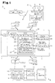
- a multifunction receiver according to one embodiment of the present invention will now be described with reference to Figs. 1 to 4 .
- a vehicle 1 includes a wireless key system 3, which operates the vehicle 1 based on a wireless signal Sw1 transmitted through wireless communication from a wireless key 2.
- the wireless key system 3 performs ID verification (wireless verification) with the vehicle 1 and the wireless key 2.
- ID verification wireless verification
- the wireless key system 3 has the vehicle 1 lock or unlock the vehicle doors.
- the wireless key 2 corresponds to an electronic key
- the wireless key system 3 corresponds to an electronic key system
- the wireless signal Swl corresponds to an ID signal.
- the wireless key 2 includes a key control unit 4, a plurality of buttons 5, and a key transmitter 6.
- the key control unit 4 manages communication operations of the wireless key 2.
- the key control unit 4 includes a memory (not shown), which registers a key ID of the wireless key 2.
- the buttons 5 are actuated to remotely control the locking and unlocking of the vehicle doors.
- the key transmitter 6 is connected to the key control unit 4 and transmits radio waves on the ultrahigh frequency (UHF) band.
- UHF ultrahigh frequency
- the vehicle 1 includes tires 8 (8a to 8d), which are mounted on a vehicle body 7, and a tire pressure monitoring system 9 that monitors the air pressure of each of the tires 8a to 8d.
- the tire pressure monitoring system 9 includes a tire communicator 10 attached to each of the tires 8a to 8d.
- the tire communicator 10 detects the air pressure of the corresponding one of the tires 8a to 8d and transmits a tire pressure signal Stp, which indicates the detection, to the vehicle body 7.
- the vehicle body 7 determines the tire pressure from the tire pressure signal Stp and notifies the driver of the determination.
- the tire communicator 10 corresponds to a tire pressure detection unit.
- Each tire communicator 10 includes a controller 11, a pressure sensor 12, a temperature sensor 13, an acceleration sensor 14, and a tire transmitter 15.
- the controller 11 includes a memory (not shown), which registers a tire ID of the corresponding one of the tires 8a to 8d.
- the pressure sensor 12, which is connected to the controller 11, detects the air pressure of the corresponding one of the tires 8a to 8d.
- the acceleration sensor 14, which is connected to the controller 11, detects rotation of the corresponding one of the tires 8a to 8d.
- the controller 11 manages the pressure sensor 12, the temperature sensor 13, the acceleration sensor 14, and the tire transmitter 15.
- the each of sensors 12-14 sends detection signals to the controller 11.
- the tire pressure monitoring system 9 of the present example 9 is of a self-excited type, and each tire communicator 10 transmits a tire pressure signal Stp in predetermined intervals.
- the tire pressure signal Stp includes tire pressure data, tire temperature data, the tire ID, and the like.
- the tire communicator 10 varies the transmission interval of the tire pressure signal Stp in accordance with an acceleration signal from the acceleration sensor 14. For example, when the vehicle 1 is moving, the tire communicator 10 transmits the tire pressure signal Stp once every minute. When the vehicle 1 is not moving and stopped, the tire communicator 10 transmits the tire pressure signal Stp once every five minutes.
- the vehicle body 7 includes a multifunction receiver 16 and a display 21.
- the multifunction receiver 16 can receive radio waves from the wireless key 2 and the tire communicators 10.
- the display 21, which is connected to the multifunction receiver 16, is arranged in an instrument panel or the like.
- the multifunction receiver 16 of the present example is shared by the wireless key system 3 and the tire pressure monitoring system 9.
- the multifunction receiver 16 includes an electronic control unit (ECU) 17, which controls the operation of the multifunction receiver 16, and a reception unit 18, which can receive UHF radio waves.
- the ECU 17 includes a memory (not shown) that registers the key ID and tire IDs.
- the reception unit 18 includes an antenna 19, which receives radio waves on the UHF band, and a reception circuit 20, which demodulates and amplifies the received radio waves.
- the ECU 17 switches signal reception modes of the multifunction receiver 16.
- the ECU 17 corresponds to a control unit.
- the wireless key system 3 and the tire pressure monitoring system 9 uses radio waves having the same frequency (signal reception frequency).
- the reception unit 18 of the present example includes the reception circuit 20 (reception IC) that only receives radio waves having the signal reception frequency.
- the ECU 17 includes a key actuator 22 and a tire pressure monitoring actuator 23.
- the key actuator 22 sets the multifunction receiver 16 in a key mode for receiving signals from the wireless key system 3.
- the tire pressure monitoring actuator 23 sets the multifunction receiver 16 in a tire pressure monitoring mode for receiving signals from the tire pressure monitoring system 9.
- the key actuator 22 and the tire pressure monitoring actuator 23 are functional sections implemented when a central processing unit (CPU) in the ECU 17 executes corresponding programs.
- CPU central processing unit
- the key actuator 22 verifies the key ID included in the wireless signal Sw1 with the key ID registered in the multifunction receiver 16 to perform wireless verification.
- the key actuator 22 locks or unlocks the vehicle doors with a door lock device 24.
- the tire pressure monitoring actuator 23 verifies the tire ID included in the tire pressure signal Stp with the tire IDs registered in the multifunction receiver 16 to perform tire ID verification.
- the tire pressure monitoring actuator 23 checks the tire pressure data included in the tire pressure signal Stp to determine whether or not the corresponding tire 8 is in a low pressure state.
- the tire pressure monitoring actuator 23 indicates a low pressure warning on the display 21.
- the tire pressure monitoring actuator 23 refers to the tire temperature data included in the tire pressure signal Stp.
- the tire pressure monitoring actuator 23 compares the tire pressure with the low pressure threshold, which is set in accordance with the tire temperature. When the tire pressure is less than the low pressure threshold, the tire pressure monitoring actuator 23 shows the location of the low pressure tire on the display 21.
- the vehicle 1 includes an ignition switch 26 which activates a power supply of the vehicle 1 when actuated by a user.
- the user selectively switches the ignition switch 26 to an ignition (IG) OFF position, an accessory (ACC) ON position, an IG ON position, and an engine start position.
- the ignition switch 26 provides the ECU 17 with power information Sv in accordance with its position. More specifically, the ignition switch 26 provides the ECU 17 with an IG OFF signal Sof when switched to the IG OFF position.
- the ignition switch 26 When switched to the ACC ON position, the ignition switch 26 provides the ECU 17 with an ACC ON signal Sac.
- the ignition switch 26 When switched to the IG ON position or engine start position, the ignition switch 26 provides the ECU 17 with an IG ON signal Son.
- the ECU 17 includes a power information acquisition section 27 that acquires power supply information Sv from the ignition switch 26.
- the power information acquisition section 27 corresponds to a power supply state detection unit.
- the multifunction receiver 16 of the present example includes a mode switching system 25 that switches the signal reception mode of the multifunction receiver 16 based on the power supply activation state and travel state of the vehicle 1.
- the mode switching system 25 of the present example sets the multifunction receiver 16 to the tire pressure monitoring mode to receive signals from the tire pressure monitoring system 9.
- the mode switching system 25 sets the multifunction receiver 16 to the key mode to receive signals from the wireless key system 3 regardless of whether or not the vehicle 1 is traveling.
- the term “traveling” refers to a state in which the power supply of the vehicle 1 is activated and the vehicle 1 is traveling.
- “stopped” refers to a state in which the power supply of the vehicle 1 is activated and the engine is running but the vehicle 1 is stopped.
- the ECU 17 also includes a travel state information acquisition section 28 that obtains travel state information Sk indicating the travel state of the vehicle 1.
- the travel state information Sk indicates whether the vehicle 1 is traveling, stopped, or parked.
- the travel state information acquisition section 28 acquires vehicle speed information Sk1 or engine speed information Sk2 from a meter ECU or the like and a starter ON signal Sst from the ignition switch 26.
- the vehicle speed information Sk1 indicates the traveling speed of the vehicle 1.
- the engine speed information Sk2 indicates the engine speed of the vehicle 1.
- the travel state information acquisition section 28 corresponds to a travel state detection unit.
- the ECU 17 includes a mode setting section 29 that sets the signal reception mode of the multifunction receiver 16 based on the power supply information Sv and travel state information Sk.
- the mode setting section 29 activates the tire pressure monitoring actuator 23 and sets the multifunction receiver 16 to the tire pressure monitoring mode to receive signals from the tire pressure monitoring system 9.
- the mode setting section 29 activates the key actuator 22 and sets the multifunction receiver 16 to the key mode to receive signals from the wireless key system 3 regardless of whether or not the vehicle 1 is traveling.
- the mode setting section 29 corresponds to a signal reception mode setting unit.
- the wireless signal Sw1 is transmitted from the wireless key 2.
- the key actuator 22 intermittently actuates the reception unit 18.
- the intermittent actuation of the reception unit 18 suppresses dark current in the vehicle 1.
- intermittent actuation of the reception unit 18 would not cause any problem since there is no need to obtain the air pressure of the tires 8 within a predetermined period.
- parked refers to a state in which the power supply of the vehicle 1 is deactivated and the engine is stopped.
- the tire pressure monitoring actuator 23 constantly activates the reception unit 18 so that the tire pressure signal Stp can constantly be received.
- the ignition switch 26 when the ignition switch 26 is switched to the ACC ON position, the ignition switch 26 provides the power information acquisition section 27 with the ACC ON signal Sac. Further, when the ignition switch 26 is switched to the IG ON position, the ignition switch 26 provides the power information acquisition section 27 with the IG ON signal Son. In this manner, when switched to a position that activates the power supply of the vehicle 1, the ignition switch 26 provides the power information acquisition section 27 with a signal indicating that the power supply of the vehicle 1 has been activated.
- the travel state information acquisition section 28 is activated and acquires the travel state information Sk from the meter ECU or the ignition switch 26.
- the travel state information Sk includes the vehicle speed information Sk1 and the engine speed information Sk2 from the meter ECU or the like and the starter ON signal Sst from the ignition switch 26.
- the mode setting section 29 sets the mode of the multifunction receiver 16 in accordance with the acquired power supply information Sv and the travel state information Sk. Based on the acquired power supply information Sv, the mode setting section 29 determines whether or not the power supply of the vehicle 1 is activated. More specifically, the mode setting section 29 determines that the power supply of the vehicle 1 is activated when one of the ACC ON signal Sac and the IG ON signal Son is received. Further, based on the acquired travel state information Sk, the mode setting section 29 determines whether or not the vehicle 1 is traveling or stopping. More specifically, when the vehicle speed is greater than or equal to a threshold, the engine speed is greater than or equal to a threshold, or the mode setting section 29 is provided with the starter ON signal Sst, the mode setting section 29 determines that the vehicle 1 is traveling or stopped.
- the mode setting section 29 activates the tire pressure monitoring actuator 23 and sets the multifunction receiver 16 to the tire pressure monitoring mode to receive signals from the tire pressure monitoring system 9. This allows the multifunction receiver 16 to receive the tire pressure signal Stp from each tire communicator 10 and perform tire pressure monitoring.
- the mode setting section 29 when the mode setting section 29 acquires the IG OFF signal Sof from the ignition switch 26, the mode setting section 29 activates the key actuator 22 regardless of whether the vehicle 1 is traveling and sets the multifunction receiver 16 to the key mode to receive signals from the wireless key system 3. In this manner, the determination for setting the multifunction receiver 16 to the key mode is based solely on the power supply information Sv and not the travel state information. This allows the multifunction receiver 16 to receive the wireless signal Sw1 from the wireless key 2 and perform wireless verification.
- the multifunction receiver 16 when the power supply of the vehicle 1 is activated and, at the same time, the vehicle 1 is traveling or stopped, the multifunction receiver 16 is set to the tire pressure monitoring mode to receive signals from the tire pressure monitoring system 9.
- the multifunction receiver 16 is set to the key mode to receive signals from the wireless key system 3 regardless of whether the vehicle 1 is traveling or stopped.
- the determination for setting the multifunction receiver 16 to the tire pressure monitoring mode is based on the activation state of the power supply of the vehicle 1 and the traveling state of the vehicle 1.
- the determination for setting the multifunction receiver 16 to the key mode is based solely on the activation state of the power supply of the vehicle 1.
- the vehicle 1 may include a remote control engine starter.
- the vehicle 1 when the engine is started by the remote engine starter, the vehicle 1 does not start traveling.
- the multifunction receiver 16 is maintained in the key mode. This allows the user to unlock the vehicle doors with the wireless key 2 when entering the vehicle 1 in a state in which the engine has been started by the remote control engine starter.
- the ignition switch 26 is not switched to the ACC OFF position or the IG OFF position.
- the multifunction receiver 16 does not switch to the key mode and is maintained in the tire pressure monitoring mode. This allows the multifunction receiver 16 to receive the tire pressure signal Stp when the vehicle 1 stops at a traffic signal.
- the present embodiment has the advantages described below.
- the electronic key system is not limited to the wireless key system 3.
- the electronic key system may be a key-operation-free system that performs short range wireless communication (communication range of several meters) with the vehicle 1 for ID verification.
- the vehicle 1 may include a key-operation-free system in addition to the wireless key system 3.
- the determination for switching the multifunction receiver 16 from the key mode to the tire pressure monitoring mode does not have to be based on the power supply activation of the vehicle and the travel state of the vehicle. For example, when the vehicle 1 includes a key-operation-free system, the determination may be based on whether the system accomplishes vehicle interior verification.
- the mode setting section 29 may set the multifunction receiver 16 to the key mode. Thereafter, when the power supply of the vehicle 1 is activated, and the vehicle speed is greater than or equal to a threshold, or the engine speed is greater than or equal to a threshold, the mode setting section 29 may switch the multifunction receiver 16 from the key mode to the tire pressure monitoring mode. Thereafter, when the power supply of the vehicle 1 is deactivated, the mode setting section 29 may switch the multifunction receiver 16 from the tire pressure monitoring mode to the key mode.
- the travel state information Sk may be position information obtained by, for example, a global positioning system (GPS).
- GPS global positioning system
- the present position of the vehicle is recognized with the GPS, and the vehicle 1 is determined to be traveling when the position of the vehicle 1 changes.
- the travel state information Sk may be obtained from a pedal depression amount signal generated by an accelerator pedal sensor that detects the depression amount of an accelerator pedal. Further, the travel state information Sk may be obtained from an acceleration signal generated by an acceleration sensor dedicated for the vehicle 1.
- the power supply information Sv does not have to be obtained from the switch signal generated by the ignition switch 26.
- the power supply information Sv may be obtained from any other signal as long as activation of the power supply of the vehicle 1 can be checked.
- a predetermined time lag may be provided when switching the multifunction receiver 16 from the tire pressure monitoring mode to the key mode. This further ensures that the multifunction receiver 16 obtains the tire pressure signal Stp.
- the operational functions of the reception unit 18 may also be changed.
- the key actuator 22 and the tire pressure monitoring actuator 23 may be configured by separate hardware circuits.
- the frequencies of the wireless signal Swl and the tire pressure signal Stp do not have to be the same and may differ from each other for a predetermined amount.
- the wireless key system 3 is not limited to a system that locks and unlocks vehicle doors.
- the wireless key system 3 may be a system that opens a closes a slide door or a back door.
- the tire pressure monitoring system 9 does not have to be of a self-excited type that transmits radio waves from the tire communicators 10.
- the tire pressure monitoring system 9 may be of an initiator type that transmits the tire pressure signal Stp when receiving radio waves from an initiator attached to the vehicle body 7.
- a vehicle (1) includes a multifunction receiver (16) that receives signals from a wireless key system (3) and a tire pressure monitoring system (9).
- the multifunction receiver (16) When a power supply of the vehicle (1) is activated and the vehicle (1) is traveling or stopped, the multifunction receiver (16) is set to receive signals from the tire pressure monitoring system (9). When the power supply of the vehicle (1) is deactivated, the multifunction receiver (16) is set to receive signals from the wireless key system (3) regardless of the travel state of the vehicle (1).
Landscapes
- Engineering & Computer Science (AREA)
- Mechanical Engineering (AREA)
- Physics & Mathematics (AREA)
- General Physics & Mathematics (AREA)
- Measuring Fluid Pressure (AREA)
- Lock And Its Accessories (AREA)
Applications Claiming Priority (1)
| Application Number | Priority Date | Filing Date | Title |
|---|---|---|---|
| JP2011158488A JP2013023868A (ja) | 2011-07-19 | 2011-07-19 | 機能統合受信機 |
Publications (2)
| Publication Number | Publication Date |
|---|---|
| EP2548748A2 true EP2548748A2 (fr) | 2013-01-23 |
| EP2548748A3 EP2548748A3 (fr) | 2013-05-29 |
Family
ID=46651374
Family Applications (1)
| Application Number | Title | Priority Date | Filing Date |
|---|---|---|---|
| EP12176487.2A Withdrawn EP2548748A3 (fr) | 2011-07-19 | 2012-07-16 | Récepteur multifonction |
Country Status (3)
| Country | Link |
|---|---|
| US (1) | US20130021149A1 (fr) |
| EP (1) | EP2548748A3 (fr) |
| JP (1) | JP2013023868A (fr) |
Cited By (3)
| Publication number | Priority date | Publication date | Assignee | Title |
|---|---|---|---|---|
| CN109397999A (zh) * | 2018-12-21 | 2019-03-01 | 李艳华 | 一种兼容rke功能的胎压监测控制方法 |
| CN111593949A (zh) * | 2020-04-08 | 2020-08-28 | 王雪峰 | 一种智能家居密码指纹锁 |
| US10766453B2 (en) * | 2017-01-24 | 2020-09-08 | Volkswagen Ag | Apparatus, key remote, and method for controlling operating conditions of a key module |
Families Citing this family (5)
| Publication number | Priority date | Publication date | Assignee | Title |
|---|---|---|---|---|
| JP5779137B2 (ja) | 2012-05-30 | 2015-09-16 | 株式会社東海理化電機製作所 | 統合受信機 |
| KR101509002B1 (ko) * | 2013-11-28 | 2015-04-14 | 현대모비스 주식회사 | 타이어 압력 모니터링 장치 및 그 방법 |
| US9999527B2 (en) * | 2015-02-11 | 2018-06-19 | Abbott Cardiovascular Systems Inc. | Scaffolds having radiopaque markers |
| JP2016175510A (ja) * | 2015-03-19 | 2016-10-06 | 株式会社オートネットワーク技術研究所 | 空気圧監視システム及びタイヤ空気圧検出装置 |
| JP7375619B2 (ja) * | 2020-03-06 | 2023-11-08 | 株式会社デンソー | 異常検知装置 |
Citations (2)
| Publication number | Priority date | Publication date | Assignee | Title |
|---|---|---|---|---|
| JP2008132911A (ja) | 2006-11-29 | 2008-06-12 | Calsonic Kansei Corp | 車載電子制御装置 |
| JP4407583B2 (ja) | 2005-07-19 | 2010-02-03 | 株式会社デンソー | 車両用受信機システム |
Family Cites Families (36)
| Publication number | Priority date | Publication date | Assignee | Title |
|---|---|---|---|---|
| DE4205911A1 (de) * | 1992-02-26 | 1993-09-02 | Uwatec Ag | Kontrollvorrichtung fuer den luftdruck von luftbereiften fahrzeugraedern |
| US6542077B2 (en) * | 1993-06-08 | 2003-04-01 | Raymond Anthony Joao | Monitoring apparatus for a vehicle and/or a premises |
| US5463374A (en) * | 1994-03-10 | 1995-10-31 | Delco Electronics Corporation | Method and apparatus for tire pressure monitoring and for shared keyless entry control |
| EP0739761B1 (fr) * | 1994-11-14 | 2003-01-22 | The Yokohama Rubber Co., Ltd. | Appareil de controle de la pression de gonflage des pneumatiques pour vehicules |
| DE19534616B4 (de) * | 1995-09-18 | 2007-01-11 | Alpha-Beta Electronics Ag | Reifendruck-Überwachungseinrichtung |
| JP3694883B2 (ja) * | 1996-03-19 | 2005-09-14 | ソニー株式会社 | 施解錠制御装置 |
| FR2798238B1 (fr) * | 1999-09-03 | 2008-05-09 | Sagem | Recepteur de surveillance de la pression des pneumatiques d'un vehicule et emetteur associe de telecommande d'organes du vehicule |
| JP4461558B2 (ja) * | 2000-03-06 | 2010-05-12 | 株式会社デンソー | 車両用タイヤ空気圧監視システム |
| DE10014076B4 (de) * | 2000-03-22 | 2004-12-09 | Nolex Ag | Reifenluftdruck-Anzeigevorrichtung |
| JP2002054331A (ja) * | 2000-08-08 | 2002-02-20 | Omron Corp | 制御装置 |
| US6597284B2 (en) * | 2000-11-29 | 2003-07-22 | Trw Inc. | Vehicle communication for tire sensor initiation and vehicle keyless entry via a shared resource |
| US6438467B1 (en) * | 2001-01-02 | 2002-08-20 | Trw Inc. | Remote control convenience and information conveyance system associated with a vehicle |
| US6420967B1 (en) * | 2001-01-31 | 2002-07-16 | Lear Corporation | System and method for shared vehicle tire pressure monitoring, remote keyless entry, and vehicle immobilization |
| DE60217826T2 (de) * | 2001-02-20 | 2007-06-14 | Siemens Vdo Automotive Corp., Auburn Hills | Kombinierter empfänger zur reifendrucküberwachung und zum schlüssellosen eintritt |
| US6885283B2 (en) * | 2001-02-20 | 2005-04-26 | Siemens Vdo Automotive Corporation | Combined tire pressure monitoring and keyless entry receiver |
| JP4078087B2 (ja) * | 2002-02-04 | 2008-04-23 | 株式会社東海理化電機製作所 | 電子キーシステム |
| US6745624B2 (en) * | 2002-02-05 | 2004-06-08 | Ford Global Technologies, Llc | Method and system for calibrating a tire pressure sensing system for an automotive vehicle |
| JP3636184B2 (ja) * | 2002-07-31 | 2005-04-06 | 株式会社デンソー | タイヤ空気圧センサのid登録方法及びid登録システムと、タイヤ空気圧監視システム、タイヤ空気圧センサ及びスマート制御システム |
| US6809638B2 (en) * | 2002-08-20 | 2004-10-26 | Trw Inc. | Apparatus with receiver having selectable threshold time constant |
| JP4007905B2 (ja) * | 2002-12-10 | 2007-11-14 | アルプス電気株式会社 | 双方向通信でタイヤ空気圧監視を行うパッシブキーレスエントリ装置 |
| EP1480399B1 (fr) * | 2003-05-21 | 2018-01-17 | Continental Automotive Systems, Inc. | Réception de signaux modulés différemment, en particulier pour systèmes d'entrée sans clé commandés à distance |
| CN1290717C (zh) * | 2003-05-25 | 2006-12-20 | 朱鹏飞 | 汽车轮胎、机器、急减速故障预警系统 |
| JP2005120656A (ja) * | 2003-10-15 | 2005-05-12 | Alps Electric Co Ltd | キーレスエントリ受信機 |
| US20050093686A1 (en) * | 2003-10-30 | 2005-05-05 | Lear Corporation | Tire pressure monitoring sensor diagnosis via vehicle antitheft and entry system |
| US7145445B2 (en) * | 2003-11-12 | 2006-12-05 | Audiovox Corporation | Vehicle tire pressure monitor |
| JP2005145351A (ja) * | 2003-11-18 | 2005-06-09 | Tokai Rika Co Ltd | 車両盗難防止装置 |
| JP2005236556A (ja) * | 2004-02-18 | 2005-09-02 | Denso Corp | 受信機及び電子機器 |
| JP2006132229A (ja) * | 2004-11-08 | 2006-05-25 | Denso Corp | 遠隔操作用車載装置 |
| JP2007039989A (ja) * | 2005-08-03 | 2007-02-15 | Alps Electric Co Ltd | キーレスエントリー装置 |
| JP4447577B2 (ja) * | 2006-05-31 | 2010-04-07 | トヨタ自動車株式会社 | 車輪状態監視システム及び車輪位置特定方法 |
| JP5067612B2 (ja) * | 2007-07-05 | 2012-11-07 | アイシン精機株式会社 | 車両ドアの遠隔制御装置 |
| US7941257B2 (en) * | 2007-10-30 | 2011-05-10 | Lear Corporation | Method and system for detecting installation of an unmonitored tire on a vehicle |
| US8026803B2 (en) * | 2008-03-31 | 2011-09-27 | Trw Automotive U.S. Llc | Apparatus and process for monitoring a vehicle condition |
| US8217776B2 (en) * | 2009-02-19 | 2012-07-10 | Chrysler Group Llc | Tire pressure sensor location identification |
| JP5186475B2 (ja) * | 2009-12-18 | 2013-04-17 | 太平洋工業株式会社 | キーレスエントリー機能を備えたタイヤ状態監視装置 |
| US8564428B2 (en) * | 2010-06-15 | 2013-10-22 | Honda Motor Co., Ltd. | Memorizing location of tires in TPMS and smart entry system |
-
2011
- 2011-07-19 JP JP2011158488A patent/JP2013023868A/ja active Pending
-
2012
- 2012-07-13 US US13/548,496 patent/US20130021149A1/en not_active Abandoned
- 2012-07-16 EP EP12176487.2A patent/EP2548748A3/fr not_active Withdrawn
Patent Citations (2)
| Publication number | Priority date | Publication date | Assignee | Title |
|---|---|---|---|---|
| JP4407583B2 (ja) | 2005-07-19 | 2010-02-03 | 株式会社デンソー | 車両用受信機システム |
| JP2008132911A (ja) | 2006-11-29 | 2008-06-12 | Calsonic Kansei Corp | 車載電子制御装置 |
Cited By (3)
| Publication number | Priority date | Publication date | Assignee | Title |
|---|---|---|---|---|
| US10766453B2 (en) * | 2017-01-24 | 2020-09-08 | Volkswagen Ag | Apparatus, key remote, and method for controlling operating conditions of a key module |
| CN109397999A (zh) * | 2018-12-21 | 2019-03-01 | 李艳华 | 一种兼容rke功能的胎压监测控制方法 |
| CN111593949A (zh) * | 2020-04-08 | 2020-08-28 | 王雪峰 | 一种智能家居密码指纹锁 |
Also Published As
| Publication number | Publication date |
|---|---|
| US20130021149A1 (en) | 2013-01-24 |
| JP2013023868A (ja) | 2013-02-04 |
| EP2548748A3 (fr) | 2013-05-29 |
Similar Documents
| Publication | Publication Date | Title |
|---|---|---|
| EP2548748A2 (fr) | Récepteur multifonction | |
| US10157542B2 (en) | User identification system and vehicular portable device | |
| EP2465737B1 (fr) | Système de clé électronique et clé électronique | |
| EP2338704B1 (fr) | Appareil de surveillance d'état de pneu avec une fonction d'entrée sans clé | |
| KR101915420B1 (ko) | 통신 시스템, 위치 판정 방법 | |
| US6906612B2 (en) | System and method for vehicle passive entry having inside/outside detection | |
| US8744482B2 (en) | Apparatus and method for wireless device detection | |
| US10214060B2 (en) | Wheel position detection device and tire-pressure detection system equipped with same | |
| US11298990B2 (en) | Tire pressure monitoring system | |
| US9908509B2 (en) | Portable device | |
| US20100231351A1 (en) | Systems and methods for controlling a smart communication system for a vehicle | |
| US20080195273A1 (en) | Vehicle Control Apparatus and Vehicle Control Method | |
| GB2385930A (en) | Combined tyre pressure monitoring and keyless entry system | |
| CN103229215A (zh) | 用于汽车的进入控制方法 | |
| US11299912B2 (en) | Vehicle electronic key | |
| US9895942B2 (en) | Method for the hands-free access to a motor vehicle and for monitoring the pressure of the tires mounted on said motor vehicle | |
| US20120203425A1 (en) | Valve identification information registration system | |
| JP2010191540A (ja) | 携帯機および車両システム | |
| JP2002188342A (ja) | 車両用施解錠装置 | |
| EP2858862B1 (fr) | Système de communication et procédé de communication | |
| JP2005178522A (ja) | タイヤ盗難検知装置 | |
| JP2006152763A (ja) | 車載用通信制御システム | |
| US20070296562A1 (en) | Passive activation vehicle system alert | |
| JP5666966B2 (ja) | 統合チューナ | |
| JP2012101709A (ja) | 車載通信機 |
Legal Events
| Date | Code | Title | Description |
|---|---|---|---|
| PUAI | Public reference made under article 153(3) epc to a published international application that has entered the european phase |
Free format text: ORIGINAL CODE: 0009012 |
|
| AK | Designated contracting states |
Kind code of ref document: A2 Designated state(s): AL AT BE BG CH CY CZ DE DK EE ES FI FR GB GR HR HU IE IS IT LI LT LU LV MC MK MT NL NO PL PT RO RS SE SI SK SM TR |
|
| AX | Request for extension of the european patent |
Extension state: BA ME |
|
| PUAL | Search report despatched |
Free format text: ORIGINAL CODE: 0009013 |
|
| AK | Designated contracting states |
Kind code of ref document: A3 Designated state(s): AL AT BE BG CH CY CZ DE DK EE ES FI FR GB GR HR HU IE IS IT LI LT LU LV MC MK MT NL NO PL PT RO RS SE SI SK SM TR |
|
| AX | Request for extension of the european patent |
Extension state: BA ME |
|
| RIC1 | Information provided on ipc code assigned before grant |
Ipc: B60C 23/04 20060101AFI20130419BHEP Ipc: G07C 9/00 20060101ALI20130419BHEP |
|
| STAA | Information on the status of an ep patent application or granted ep patent |
Free format text: STATUS: THE APPLICATION IS DEEMED TO BE WITHDRAWN |
|
| 18D | Application deemed to be withdrawn |
Effective date: 20131130 |