EP2548802A2 - Vielseitiges System für Flugzeuge - Google Patents
Vielseitiges System für Flugzeuge Download PDFInfo
- Publication number
- EP2548802A2 EP2548802A2 EP12176470A EP12176470A EP2548802A2 EP 2548802 A2 EP2548802 A2 EP 2548802A2 EP 12176470 A EP12176470 A EP 12176470A EP 12176470 A EP12176470 A EP 12176470A EP 2548802 A2 EP2548802 A2 EP 2548802A2
- Authority
- EP
- European Patent Office
- Prior art keywords
- aircraft
- motor
- power system
- air breathing
- versatile
- Prior art date
- Legal status (The legal status is an assumption and is not a legal conclusion. Google has not performed a legal analysis and makes no representation as to the accuracy of the status listed.)
- Withdrawn
Links
Images

Classifications
-
- B—PERFORMING OPERATIONS; TRANSPORTING
- B64—AIRCRAFT; AVIATION; COSMONAUTICS
- B64C—AEROPLANES; HELICOPTERS
- B64C25/00—Alighting gear
- B64C25/32—Alighting gear characterised by elements which contact the ground or similar surface
- B64C25/405—Powered wheels, e.g. for taxing
-
- B—PERFORMING OPERATIONS; TRANSPORTING
- B64—AIRCRAFT; AVIATION; COSMONAUTICS
- B64D—EQUIPMENT FOR FITTING IN OR TO AIRCRAFT; FLIGHT SUITS; PARACHUTES; ARRANGEMENT OR MOUNTING OF POWER PLANTS OR PROPULSION TRANSMISSIONS IN AIRCRAFT
- B64D41/00—Power installations for auxiliary purposes
-
- B—PERFORMING OPERATIONS; TRANSPORTING
- B64—AIRCRAFT; AVIATION; COSMONAUTICS
- B64D—EQUIPMENT FOR FITTING IN OR TO AIRCRAFT; FLIGHT SUITS; PARACHUTES; ARRANGEMENT OR MOUNTING OF POWER PLANTS OR PROPULSION TRANSMISSIONS IN AIRCRAFT
- B64D2205/00—Aircraft with means for ground manoeuvring, such as taxiing, using an auxiliary thrust system, e.g. jet-engines, propellers or compressed air
-
- Y—GENERAL TAGGING OF NEW TECHNOLOGICAL DEVELOPMENTS; GENERAL TAGGING OF CROSS-SECTIONAL TECHNOLOGIES SPANNING OVER SEVERAL SECTIONS OF THE IPC; TECHNICAL SUBJECTS COVERED BY FORMER USPC CROSS-REFERENCE ART COLLECTIONS [XRACs] AND DIGESTS
- Y02—TECHNOLOGIES OR APPLICATIONS FOR MITIGATION OR ADAPTATION AGAINST CLIMATE CHANGE
- Y02T—CLIMATE CHANGE MITIGATION TECHNOLOGIES RELATED TO TRANSPORTATION
- Y02T50/00—Aeronautics or air transport
- Y02T50/80—Energy efficient operational measures, e.g. ground operations or mission management
Definitions
- This invention discloses a versatile power system for aircraft, comprising an aircraft power unit which provides thrust and self-propelled landing gear wheels. It is included in the technical field of propulsion and power units for the aeronautic industry.
- Auxiliary power units are currently employed in commercial aircrafts in order to supply power when no other sources are available (main engines, ground power units, and so on).
- APU are turbo-shaft engines driving an electric generator and sometimes a pneumatic load compressor.
- the turbo-machines considered for this role generate no significant propulsive force as most of the power is extracted from the gas in order to drive the electric and pneumatic load. It is common practice in aircraft design to place the APU at the tailcone.
- Standard aircraft procedures at airports require ground handling equipment to begin aircraft operations, like taxi tractors which are required when pushback is necessary to move the aircraft toward the taxiways. All this equipment increases operating cost. Furthermore, during taxi phase main engines must work out of their optimal performance conditions, requiring high fuel consumption. It is desirable to overcome all these disadvantages, by developing a new versatile power system suitable to produce aircraft movement on ground and thrust during some operation stages as well. Moreover, providing an APU with thrust features makes downsizing main engines possible, as additional thrust from APU is available for the most demanding mission phases.
- Document WO 2007/053932 A1 discloses a method and a system for taxiing an aircraft, and it comprises a gas turbine engine having an electrical motor engaged with a low pressure spool of the engine.
- the low pressure spool has a propulsor which causes a major portion of the thrust for moving the aircraft during taxiing.
- Document US 2008/0059053 A1 shows a method for reducing the turnaround time of an aircraft having at least one self-propelled undercarriage wheel, wherein turbines are turned off until takeoff or after landing.
- Document EP 1 069 044 B1 reveals an auxiliary power unit which can provide auxiliary thrust when required.
- the invention has developed an aircraft versatile power system comprising,
- the power converter transforms shaft motion from the air breathing engine into electric energy, hydraulic energy or pneumatic energy.
- the motor in turn, can be an electric motor, a hydraulic motor or a pneumatic motor respectively.
- the air breathing engine may be a turbojet or a turbofan.
- the air breathing engine has at least an air intake that provides air supply when open, and the air intake presents no additional aerodynamic drag when it is closed.
- the invention also discloses a method to operate an aircraft, using a versatile power system which comprises:
- the versatile power system works in mode 1, providing power supply to the aircraft.
- the versatile power system works in mode 1, providing power supply to the aircraft, and the aircraft is moved using the motor which turns the landing gear wheels, moving the aircraft towards a taxiway.
- the versatile power system works in mode 2, providing power supply and thrust to the aircraft, and the aircraft is moved using the motor and due to the thrust provided by the nozzle as well.
- the motor is switched off and thrust is provided by main engines, and the air breathing engine may either remain operative providing additional thrust (mode 3), or may be shut down.
- the versatile power system normally works in mode 3.
- VPS versatile power system
- VPU air breathing engine, or versatile power unit
- 3 landing gear wheels
- 4 VPS motor
- 5 power distribution grid
- 6 VPS power converter
- 7 aircraft system
- 8 VPS intake flap actuator
- 9 VPS air intake
- 10 air supply
- 11 mechanical drive
- 12 air breathing main engines
- 13 power transmission
- 14 motor shaft
- 21 fan
- 22 compressor
- 23 combustion chamber
- 24 turbine
- 25 nozzle.
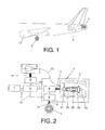
- Figure 1 shows a partial side view of an aircraft having air breathing main engines (12) and an air breathing engine (2) at the tailcone. At least an air intake (9) provides air supply (10) to the air breathing engine (2).
- Figure 2 represents the relationship among the versatile power unit (2) and other aircraft systems.
- the versatile power system (1) for aircraft disclosed by the invention is a combination of an air breathing engine (2) (a turbo-machine, usually a turbojet or a turbofan) installed at the aircraft tailcone, a power converter (6), and a motor (4) preferably installed nearby the landing gear wheels (3).
- a turbo-machine usually a turbojet or a turbofan
- the air engine (2) turbo-machine is a turbojet
- it comprises a compressor (22), a combustion chamber (23), a turbine (24), and a nozzle (25).
- the air engine (2) turbo-machine is a turbofan
- it comprises a fan (21), a compressor (22), a combustion chamber (23), a turbine (24), and a nozzle (25).
- the air breathing engine (2) turbo-machine works as a versatile power unit, due to the fact that it is a variable cycle turbo-machine which is able to produce either shaft energy through a mechanical drive (11), or thrust for the aircraft propulsion through the nozzle (25), or both simultaneously. Therefore, the air breathing engine (2) is also called versatile power unit (VPU).
- VPU versatile power unit
- VPS The versatile power system, VPS, (1) operates in three different working modes.
- the air breathing engine (2) works as a turbo-shaft, driving the power converter (6) such as electric generators, hydraulic pumps or pneumatic compressors. Shaft power produced by the air breathing engine (2) is transferred to the power converter (6) through a mechanical drive (11). In addition, it is possible to extract pneumatic power directly from the first stages of the compressor (22).
- the air breathing engine (2) works as a turbomachine, generating thrust through the nozzle (25) in addition to the shaft power supplied in mode 1.
- This force can be employed to impulse the aircraft when low thrust is demanded (taxi), or to help air breathing main engines (12) when necessary (i.e. during takeoff, climb and descend phases, or in case of an engine failure).
- the air breathing engine (2) works solely as a turbofan, generating thrust through the nozzle (25), again when necessary (during takeoff, climbing, or in case of an main engine (12) failure).
- the versatile power system, VPU, (1) additionally includes a motor (4) placed preferably nearby the landing gear and intended to drive the landing gear wheels (3).
- the motor (4) works both ways, turning counterclockwise or clockwise. This counterclockwise or clockwise spinning movement is transmitted through a motor shaft (14) and a mechanical drive (11) to the aircraft landing gear wheels (3), producing an aeroplane on-ground displacement forward or backward respectively.
- the air breathing engine (2) supplies power to the power converter (6) through a mechanical drive (11).
- Power generated by the power converter (6) can be mechanic, electric, hydraulic or pneumatic power.
- This power generated by the power converter (6) is distributed to the aircraft power distribution grid (5) through power transmission means (13) well known in the state of the art (shafts, electric wires, and hydraulic or pneumatic pipes).
- the motor (4) which provides movement to the landing gear wheels (3) can also be mechanic, electric, hydraulic or pneumatic type.
- On board equipment requires power supply to satisfy the aircraft energy loads; power supply is provided by the power distribution grid (5).
- the power transmission means (13) transfer power from the power converter (6) to the power distribution grid (5).
- the power distribution grid (5) uses the power transmission means (13) for providing power supply to the aircraft systems (7) demanding power and other relevant elements like the motor (4) or an intake flap actuator (8).
- the intake flap actuator (8) opens the air intake (9) when the air breathing engine (2) is working; a mechanical drive (11) is used for opening the air intake (9), providing air supply (10) to the air engine (2).
- the VPS air intake (9) remains closed minimizing the aerodynamic drag.
- the versatile power system (1) operation is selected for each stage of the flight, among the following modes:
- the motor (4) When power for the landing gear (3) wheel propulsion is required, the motor (4) needs a power supply that is provided by the power distribution grid (5), or even directly by the power converter (6). Power transmission means (13) supply the power requested by the motor (4). Afterwards the motor (4) transfers power to a mechanical drive (11), which moves a shaft (14) that makes the landing gear wheels (3) rotate. The motor shaft (14) can rotate either clockwise or counterclockwise, making the landing gear wheels (3) turn either clockwise or counterclockwise as well. This counterclockwise or clockwise turning movement produces the aircraft on-ground displacement forward or backward respectively.
- the aircraft equipped with the versatile power system (1) operates as follows:
- Table 1 provides a complete understanding on the functionality of the air breathing main engines (12) and VPS (1) during the different flight phases.
- “1” means “ON”, and “0” means “OFF”.
- Table 1 - Uses of the main engines and VPS during different flight phases Flight phase Main engines VPS (VPU & motor on landing gear) Motor on landing gear VPU operation mode Mode 1 Power generation Mode 2 Thrust + power generation Mode 3 Thrust Gate 0 1 0 1 0 0 0 Pushback 0 1 1 1 0 0 0 Taxi out 0 1 1 0 1 0 Take off & climbing 1 1/0 0 0 0 0 0 0 0 0 Descent & landing 1 0 0 0 0 0 0 0 Taxi in 0 1 1 0 1 0 0 0 0
- a versatile power system (1) installed in a two engine aircraft weighing around 80 tons.
- Such aircraft may comprise:
- the motor (4) and the gearbox are designed and sized in order to provide the required torque (around 20 kN-m) to overcome breakaway force and the power (around 20 kW) to drive the aircraft backwards or forwards at typical pushback speed (usually lower than 6 km/h).
- the thrust from the air breathing engine (2) may be around 20-30 kN; this value is enough to allow forward propulsion at conventional taxi speeds (around 30 knots) and acceleration levels.
- the air breathing engine (2) works in three different modes as it has been mentioned:
- the air breathing engine (2) receives air supply (10) through a couple of symmetric air intakes (9) placed in the lower part of the fuselage but slightly displaced to the sides. These air intakes (9) can be retracted in order to minimize aerodynamic impact when the versatile power system (1) is used.
- the air breathing main engines of the aircraft can be reduced in size around 15% as compared to an aircraft without the versatile power system (1).
Landscapes
- Engineering & Computer Science (AREA)
- Aviation & Aerospace Engineering (AREA)
- Mechanical Engineering (AREA)
- Transmission Devices (AREA)
- Electric Propulsion And Braking For Vehicles (AREA)
- Arrangement Of Transmissions (AREA)
Applications Claiming Priority (1)
| Application Number | Priority Date | Filing Date | Title |
|---|---|---|---|
| ES201131220A ES2398316B1 (es) | 2011-07-18 | 2011-07-18 | Sistema versátil de potencia en aeronaves |
Publications (2)
| Publication Number | Publication Date |
|---|---|
| EP2548802A2 true EP2548802A2 (de) | 2013-01-23 |
| EP2548802A3 EP2548802A3 (de) | 2017-06-21 |
Family
ID=46603574
Family Applications (1)
| Application Number | Title | Priority Date | Filing Date |
|---|---|---|---|
| EP12176470.8A Withdrawn EP2548802A3 (de) | 2011-07-18 | 2012-07-13 | Vielseitiges System für Flugzeuge |
Country Status (6)
| Country | Link |
|---|---|
| US (1) | US20130181088A1 (de) |
| EP (1) | EP2548802A3 (de) |
| CN (1) | CN103112592A (de) |
| CA (1) | CA2783253A1 (de) |
| ES (1) | ES2398316B1 (de) |
| RU (1) | RU2012130452A (de) |
Cited By (2)
| Publication number | Priority date | Publication date | Assignee | Title |
|---|---|---|---|---|
| EP2808252A1 (de) * | 2013-05-28 | 2014-12-03 | Hamilton Sundstrand Corporation | Integriertes hydrostatisches Getriebe für elektronische Rollvorgänge |
| WO2014198920A1 (fr) * | 2013-06-14 | 2014-12-18 | European Aeronautic Defence And Space Company Eads France | Avion à dispositif d'assistance au décollage et procédé de mise en oeuvre |
Families Citing this family (20)
| Publication number | Priority date | Publication date | Assignee | Title |
|---|---|---|---|---|
| EP2969759B1 (de) * | 2013-03-13 | 2016-11-30 | Rolls-Royce North American Technologies, Inc. | Generator für einen flugkörper |
| US9193451B2 (en) * | 2013-04-22 | 2015-11-24 | Ival O. Salyer | Aircraft using turbo-electric hybrid propulsion system for multi-mode operation |
| GB201315012D0 (en) | 2013-08-22 | 2013-10-02 | Airbus Uk Ltd | Aircraft autonomous pushback |
| US20150283908A1 (en) * | 2014-04-02 | 2015-10-08 | Hamilton Sundstrand Corporation | Systems utilizing a controllable voltage ac generator system |
| US20170036773A1 (en) * | 2015-08-07 | 2017-02-09 | Pratt & Whitney Canada Corp. | Inflight power management for aircraft |
| US9771149B2 (en) * | 2015-10-30 | 2017-09-26 | Honeywell International Inc. | Gate departure system for aircraft |
| GB201519755D0 (en) * | 2015-11-09 | 2015-12-23 | Airbus Operations Ltd And Airbus Operations Gmbh | Cooling of a motor for driving an aircraft wheel |
| US20180265213A1 (en) * | 2017-03-17 | 2018-09-20 | Hamilton Sundstrand Corporation | Emergency power generation via electrically driven tail cone boundary layer ingestion thruster |
| US10822100B2 (en) * | 2017-06-26 | 2020-11-03 | General Electric Company | Hybrid electric propulsion system for an aircraft |
| US11149649B2 (en) | 2018-08-17 | 2021-10-19 | Raytheon Technologies Corporation | Hybrid gas turbine engine system powered warm-up |
| US11732639B2 (en) | 2019-03-01 | 2023-08-22 | Pratt & Whitney Canada Corp. | Mechanical disconnects for parallel power lanes in hybrid electric propulsion systems |
| US11628942B2 (en) | 2019-03-01 | 2023-04-18 | Pratt & Whitney Canada Corp. | Torque ripple control for an aircraft power train |
| CA3132285A1 (en) | 2019-03-01 | 2020-09-10 | Pratt & Whitney Canada Corp. | Torque balancing for hybrid electric propulsion systems and aircraft utilizing hybrid electric propulsion systems |
| WO2020180374A1 (en) | 2019-03-01 | 2020-09-10 | United Technologies Advanced Projects Inc. | Distributed propulsion configurations for aircraft having mixed drive systems |
| WO2020190344A2 (en) | 2019-03-18 | 2020-09-24 | United Technologies Advanced Projects Inc. | Architectures for hybrid-electric propulsion |
| US11486472B2 (en) | 2020-04-16 | 2022-11-01 | United Technologies Advanced Projects Inc. | Gear sytems with variable speed drive |
| US11827372B2 (en) | 2020-05-15 | 2023-11-28 | Pratt & Whitney Canada Corp. | Engine characteristics matching |
| US11794917B2 (en) | 2020-05-15 | 2023-10-24 | Pratt & Whitney Canada Corp. | Parallel control loops for hybrid electric aircraft |
| US12030651B2 (en) | 2021-01-05 | 2024-07-09 | Pratt & Whitney Canada Corp. | Parallel hybrid power plant with hollow motor |
| US11999500B2 (en) * | 2021-10-20 | 2024-06-04 | General Electric Company | Deployable inlet assembly for aerial vehicle |
Citations (3)
| Publication number | Priority date | Publication date | Assignee | Title |
|---|---|---|---|---|
| EP1069044A2 (de) | 1999-07-15 | 2001-01-17 | The Boeing Company | Hilfskraft- und Hilfsschubantrieb |
| WO2007053932A1 (en) | 2005-11-09 | 2007-05-18 | Pratt & Whitney Canada Corp. | Method and system for taxiing an aircraft |
| US20080059053A1 (en) | 2006-08-29 | 2008-03-06 | Isaiah Watas Cox | Turnaround methods |
Family Cites Families (10)
| Publication number | Priority date | Publication date | Assignee | Title |
|---|---|---|---|---|
| US4936748A (en) * | 1988-11-28 | 1990-06-26 | General Electric Company | Auxiliary power source in an unducted fan gas turbine engine |
| GB9408075D0 (en) * | 1994-04-22 | 1994-06-15 | Greenlite Limited | Improvements in or relating to aircraft |
| US7445178B2 (en) * | 2004-09-28 | 2008-11-04 | The Boeing Company | Powered nose aircraft wheel system |
| CN101172523A (zh) * | 2006-10-31 | 2008-05-07 | 通用电气公司 | 辅助动力装置总成 |
| US7980509B2 (en) * | 2007-03-08 | 2011-07-19 | The Ashman Group, Llc | Aircraft taxiing systems |
| FR2928135B1 (fr) * | 2008-02-29 | 2010-09-03 | Airbus France | Systeme de propulsion arriere d'avion a entrees d'air laterales escamotables et avion comportant un tel systeme. |
| DE102009010243A1 (de) * | 2009-02-24 | 2010-09-02 | Airbus Deutschland Gmbh | Leistungserzeugungs-Vorrichtung sowie Rumpf-Bauteil mit einer solchen Leistungserzeugungs-Vorrichtung |
| FR2954283B1 (fr) * | 2009-12-23 | 2012-03-02 | Hispano Suiza Sa | Aeronef comportant un demarreur-generateur electrique pour le ou chaque turboreacteur et un train d'aterrissage equipe d'un moteur electrique de manoeuvre au sol |
| US8622342B2 (en) * | 2011-06-17 | 2014-01-07 | Embraer S.A. | On-board aircraft auxiliary power systems having dual auxiliary power units |
| US8444083B2 (en) * | 2011-06-30 | 2013-05-21 | Hamilton Sundstrand Corporation | Auxiliary power unit inlet |
-
2011
- 2011-07-18 ES ES201131220A patent/ES2398316B1/es not_active Expired - Fee Related
-
2012
- 2012-07-13 EP EP12176470.8A patent/EP2548802A3/de not_active Withdrawn
- 2012-07-16 CA CA2783253A patent/CA2783253A1/en not_active Abandoned
- 2012-07-17 CN CN2012102478485A patent/CN103112592A/zh active Pending
- 2012-07-17 US US13/550,929 patent/US20130181088A1/en not_active Abandoned
- 2012-07-17 RU RU2012130452/11A patent/RU2012130452A/ru not_active Application Discontinuation
Patent Citations (3)
| Publication number | Priority date | Publication date | Assignee | Title |
|---|---|---|---|---|
| EP1069044A2 (de) | 1999-07-15 | 2001-01-17 | The Boeing Company | Hilfskraft- und Hilfsschubantrieb |
| WO2007053932A1 (en) | 2005-11-09 | 2007-05-18 | Pratt & Whitney Canada Corp. | Method and system for taxiing an aircraft |
| US20080059053A1 (en) | 2006-08-29 | 2008-03-06 | Isaiah Watas Cox | Turnaround methods |
Cited By (4)
| Publication number | Priority date | Publication date | Assignee | Title |
|---|---|---|---|---|
| EP2808252A1 (de) * | 2013-05-28 | 2014-12-03 | Hamilton Sundstrand Corporation | Integriertes hydrostatisches Getriebe für elektronische Rollvorgänge |
| US9139291B2 (en) | 2013-05-28 | 2015-09-22 | Hamilton Sundstrand Corporation | Integrated hydrostatic transmission for electronic taxiing operations |
| WO2014198920A1 (fr) * | 2013-06-14 | 2014-12-18 | European Aeronautic Defence And Space Company Eads France | Avion à dispositif d'assistance au décollage et procédé de mise en oeuvre |
| FR3006991A1 (fr) * | 2013-06-14 | 2014-12-19 | Eads Europ Aeronautic Defence | Avion a dispositif d'assistance au decollage et procede de mise en oeuvre |
Also Published As
| Publication number | Publication date |
|---|---|
| US20130181088A1 (en) | 2013-07-18 |
| RU2012130452A (ru) | 2014-01-27 |
| ES2398316R1 (es) | 2013-06-12 |
| EP2548802A3 (de) | 2017-06-21 |
| ES2398316B1 (es) | 2014-04-29 |
| CA2783253A1 (en) | 2013-01-18 |
| ES2398316A2 (es) | 2013-03-15 |
| CN103112592A (zh) | 2013-05-22 |
Similar Documents
| Publication | Publication Date | Title |
|---|---|---|
| EP2548802A2 (de) | Vielseitiges System für Flugzeuge | |
| US11046428B2 (en) | Tiltrotor propulsion system for an aircraft | |
| EP4225645B1 (de) | Flugzeug mit einem antriebs- und energiesystem für emissionsarmen reiseflug | |
| Wiegand | F-35 air vehicle technology overview | |
| US10252797B2 (en) | Tiltrotor propulsion system for an aircraft | |
| US10384773B2 (en) | Tiltrotor propulsion system for an aircraft | |
| US12043399B2 (en) | Hybrid propulsion system for use during uncommanded thrust loss and method of operating | |
| US20200017228A1 (en) | Parallel Hybrid Aircraft | |
| US10392106B2 (en) | Tiltrotor propulsion system for an aircraft | |
| EP3421369A1 (de) | Antriebssystem für ein flugzeug | |
| US20160355272A1 (en) | Aircraft propulsion system | |
| US20180065739A1 (en) | Tiltrotor propulsion system for an aircraft | |
| US11015521B2 (en) | Aircraft propulsion assembly equipped with a main fan and with at least one offset fan | |
| ITRM970762A1 (it) | Sistema per la trasformazione di un aeromobile a decollo e volo orizzontale autosostentato in aeromobile integrato, ibrido a decollo | |
| EP4385889A1 (de) | Elektrischer antrieb | |
| CN101108655A (zh) | 用于飞机的电动辅助动力系统结构 | |
| EP3778401A1 (de) | Rollen eines flugzeugs mit hybridantrieb | |
| McKay et al. | The ultrafan engine and aircraft based thrust reversing | |
| Thauvin et al. | Hybrid regional aircraft: A comparative review of new potentials enabled by electric power | |
| EP3584168B1 (de) | Turbomaschine für ein flugzeug | |
| Lents et al. | Parallel hybrid propulsion & secondary power system architecture exploration and evaluation | |
| EP3546349A1 (de) | Multifunktionsstrebe | |
| EP4015389B1 (de) | Energieverwaltungssystem für ein flugzeug | |
| US20130175388A1 (en) | Method and device for driving at least one landing gear wheel of an aircraft by means of a wheel motor | |
| Steiner et al. | Performance and sizing of transport aircraft employing electrically-powered distributed propulsion |
Legal Events
| Date | Code | Title | Description |
|---|---|---|---|
| PUAI | Public reference made under article 153(3) epc to a published international application that has entered the european phase |
Free format text: ORIGINAL CODE: 0009012 |
|
| AK | Designated contracting states |
Kind code of ref document: A2 Designated state(s): AL AT BE BG CH CY CZ DE DK EE ES FI FR GB GR HR HU IE IS IT LI LT LU LV MC MK MT NL NO PL PT RO RS SE SI SK SM TR |
|
| AX | Request for extension of the european patent |
Extension state: BA ME |
|
| PUAL | Search report despatched |
Free format text: ORIGINAL CODE: 0009013 |
|
| AK | Designated contracting states |
Kind code of ref document: A3 Designated state(s): AL AT BE BG CH CY CZ DE DK EE ES FI FR GB GR HR HU IE IS IT LI LT LU LV MC MK MT NL NO PL PT RO RS SE SI SK SM TR |
|
| AX | Request for extension of the european patent |
Extension state: BA ME |
|
| RIC1 | Information provided on ipc code assigned before grant |
Ipc: B64C 25/40 20060101AFI20170515BHEP |
|
| STAA | Information on the status of an ep patent application or granted ep patent |
Free format text: STATUS: THE APPLICATION IS DEEMED TO BE WITHDRAWN |
|
| 18D | Application deemed to be withdrawn |
Effective date: 20171222 |