EP2548820A1 - Müllbehälter - Google Patents
Müllbehälter Download PDFInfo
- Publication number
- EP2548820A1 EP2548820A1 EP11174718A EP11174718A EP2548820A1 EP 2548820 A1 EP2548820 A1 EP 2548820A1 EP 11174718 A EP11174718 A EP 11174718A EP 11174718 A EP11174718 A EP 11174718A EP 2548820 A1 EP2548820 A1 EP 2548820A1
- Authority
- EP
- European Patent Office
- Prior art keywords
- container
- waste
- shelf device
- wall
- waste container
- Prior art date
- Legal status (The legal status is an assumption and is not a legal conclusion. Google has not performed a legal analysis and makes no representation as to the accuracy of the status listed.)
- Granted
Links
Images


Classifications
-
- B—PERFORMING OPERATIONS; TRANSPORTING
- B65—CONVEYING; PACKING; STORING; HANDLING THIN OR FILAMENTARY MATERIAL
- B65F—GATHERING OR REMOVAL OF DOMESTIC OR LIKE REFUSE
- B65F1/00—Refuse receptacles; Accessories therefor
- B65F1/14—Other constructional features; Accessories
-
- B—PERFORMING OPERATIONS; TRANSPORTING
- B65—CONVEYING; PACKING; STORING; HANDLING THIN OR FILAMENTARY MATERIAL
- B65F—GATHERING OR REMOVAL OF DOMESTIC OR LIKE REFUSE
- B65F1/00—Refuse receptacles; Accessories therefor
- B65F1/14—Other constructional features; Accessories
- B65F2001/1489—Refuse receptacles adapted or modified for gathering compostable domestic refuse
Definitions
- the present invention relates to a waste container according to the preamble of claim 1.
- such waste containers comprise a container body for picking up waste.
- the container body comprises a base and at least one container wall.
- the container body can be closed by use of a container lid which is mounted on the container body.
- Such waste containers can be used for picking up and storing all kinds of waste.
- One field of application of such waste containers is the storage of bio waste.
- the freezing of bio waste in waste containers, so called bio bins, is a since long debated problem especially on the Nordic Markets.
- the wet bio waste freezes to an ice lump and gets stuck in the waste container causing big problems for the collectors.
- a common recommendation from the municipalities is to place the bio waste in a paper bag outside the container body or on top of the container lid until coming with next bag. According to such a solution the first paper bag containing bio waste will have been frozen and will not get stuck in the waste container.
- this solution is neither esthetic nor practical, due to disfigurement of the area around the waste container, damaging to the paper bags by animals and the like.
- a waste container comprising a container body for picking up waste, said container body comprising a container base and at least one container wall.
- the waste container is characterized in that at least one shelf device for temporary storage of a waste portion is provided said at least one shelf device being arranged inside the container body on at least one container wall.
- the present invention is based on the general finding that a shelf device which is capable of temporarily storing a waste portion, a bio waste portion for example, is mounted inside the container body. Therefore, the waste portion is stored inside the container body.
- a waste container is provided.
- This waste container is adapted to pick up waste.
- the present invention is not limited to specific types of waste containers or to specific types of waste or waste fractions that can be picked up and stored by said waste container.
- the present invention is directed to a waste container for picking up bio waste.
- waste container can function as a so called "bio bin”.
- the waste container comprises a container body.
- the container body preferably comprises a container base. At least one container wall projects from said container base to an upper edge of said container body.
- the waste container can comprise one single container wall, for example if the waste container body is round shaped, oval shaped or the like.
- the container wall comprises different, for example four, walls, which are connected to one another.
- the container wall can comprise a front wall, a rear wall and two side walls.
- the container body comprising one container wall or more than one container walls can be manufactured and provided as a one-piece container body.
- the container wall and the container base border or delimit a container internal space, said internal space defining the space for picking up waste.
- the container body comprises a collecting opening for collecting waste.
- this collecting opening is bordered or delimited by the container wall or walls. In such a case, the collecting opening extends over the entire cross-section of the container body at the upper ending of the container body.
- At least one shelf device is provided, said shelf device being adapted for temporary storage of a waste portion.
- the present invention is not limited to a specific number of shelf devices. According to a preferred embodiment, one single shelf device is provided. However, according to different embodiments, two or more shelf devices could be provided. The number of shelf devices particularly depends on the configuration and size of the waste container.
- the shelf device is adapted to temporarily storing a waste portion.
- the present invention is not limited to specific types of waste that can be stored.
- a bio waste portion can be stored.
- a waste portion can be an amount of waste that is preferably stored inside a box or a bag, a paper bag for example.
- a waste portion is an amount of bio waste that is stored inside a paper bag.
- the present invention is not limited to specific types or arrangements or designs of waste portions.
- the at least one shelf device is arranged inside the container body on at least one container wall.
- the shelf device can be fixed or is fixed at the inner surface of the container wall, said inner surface bordering or delimiting the container internal space said internal space defining the space for picking up waste.
- the shelf device is arranged inside the container body and therefore, inside the waste container.
- the shelf device is adapted to pick up a waste portion, a waste bag for example, and then when coming with the next waste portion, drop the waste portion stored on the shelf device into the container body and place the next waste portion on the shelf device.
- the shelf device can be arranged in a way that is swings against the container wall, when the waste container is discharged. Once the waste container has been replaced to the ground after the discharge procedure has been finished, the shelf device can swing into a position where it can pick up a waste portion again. More details of such a preferred embodiment are described in moiré detail further below.
- the waste container according to the present invention which comprises at least one shelf device inside the container body allows dehydrating the waste, particularly the bio waste, which is stored on said shelf device, during summer, thus reducing the weight of the waste and the occurrence of bad odors.
- the waste portion freezes to a bloc on the shelf device which facilitates the discharge procedure of the waste container.
- the waste portion may remain on the shelf device until the next waste portion id delivered.
- the present invention provides a solution which allows a waste portion, a bag with bio waste for example to be placed on the shelf device for ventilation during summertime and "pre-freezing” on winter time, in order to reduce smell and freezing problems.
- the shelf device can be mounted on the container wall in different ways. Therefore the present invention is not delimited to any specific embodiments. However, in the following, different preferred embodiments are described in greater detail how the shelf device can be arranged at a container wall.
- At least one shelf device is pivot mounted on at least one container wall.
- the at least one shelf device is pivot mounted via a pivot axis, which can be denoted as a swivelling axis or a rotational axis as well.
- a swivelling arrangement or connection is a connection that allows the connected object, the shelf device for example, to rotate horizontally and/or vertically.
- a swivelling connection is a kind of connection which allows the shelf device to turn round on a horizontal axis in relation to said container body.
- a rotational arrangement or connection is a connection, which allows an object, the shelf device for example, to turn around a centre or axis in a circular motion.
- a pivot axis is an axis consisting of a shaft that supports something that turns, for example the shelf device.
- At least one shelf device is mounted on at least one container wall via a hinge device.
- the shelf device is hinged to allow problem free emptying of the waste container.
- At least one shelf device is pivot mounted on at least one container wall to allow a pivot movement of the shelf device from an orientation parallel to the container wall into an orientation perpendicular or almost perpendicular to the container wall.
- An orientation parallel to the container wall is preferably chosen, when the waste container is discharged.
- An orientation perpendicular, which is particularly an 90 degree orientation, or almost perpendicular to the container wall is preferably chosen, when the shelf device is ready or in use for picking up a waste portion.
- the shelf device is pivot mounted on the container wall around a first axis; a swivelling axis, a rotational axis, a pivot axis or the like.
- this can be realised via a hinge device, a pivot joint, a swivel joint or a rotational joint for example.
- the shelf device is pivot mounted via a hinge device, a knuckle joint and the like on the container wall.
- the shelf device can be swung up and down. In its swung up state the shelf device is preferably oriented in parallel to the container wall. In this state the waste container can be discharged by use of an adequate equipped waste collecting vehicle for example.
- the shelf device In its swung down state, which can be 90 degrees for example, the shelf device is preferably oriented perpendicular or almost perpendicular to the container wall. In this state a waste portion can be stored on said shelf device.
- the shelf device is hinged to allow problem free emptying of the bin. Thus, it folds to the side of the waste container when emptied and then falls back in supported position again when the waste container is replaced on ground.
- At least one shelf device is mounted on at least one container wall via a plug connection.
- the container wall or the shelf device comprises at least one bolt of protrusion which fit into respective recesses or openings or holes inside the shelf device or container wall. It the waste container is discharged, the shelf device is removed from the container body. Once the discharging procedure has been finished the shelf device is plugged to the container wall again.
- a fixing device for fixation of at least one shelf device in at least one defined position.
- the present invention is not limited to specific types of fixing devices.
- the fixing device is adapted to fix, fasten, secure, lock at least one shelf device in at least one defined position, alignment or adjustment.
- the present invention is not limited to specific positions or a number of defined positions.
- the fixing device can be adapted to fix at least one shelf device in a position parallel to the container wall and/or in a position perpendicular or almost perpendicular to the container wall.
- the shelf device can be detachably or non-detachably mounted on the container wall.
- At least one shelf device is formed as an arrangement of rods.
- the arrangement can comprise one or more rods.
- the arrangement of rods is formed in a way, that the rods themselves cover a minimum of surface area.
- the rods shall provide a maximum of support points for supporting the waste portion to be stored.
- the arrangement of rods can provide a curved or looped or strapped or meander shaped configuration.
- the container body comprises a rear wall, a front wall and two side walls. At least one shelf device is arranged on the rear wall and/or on at least one side wall.
- At least one container wall comprises at least one ventilation aperture and that at least one shelf device is arranged on the container wall in the area or vicinity of the at least one ventilation aperture.
- Such ventilation apertures are preferably provided, when the waste container is used for storing bio waste. Preferably more than one ventilation aperture is provided.
- the shelf device is mounted on the container wall by use of such ventilation apertures.
- fastening apertures for fastening the shelf device have to be brought, drilled for example, into the container wall in advance.
- the shelf device can be sold to already existing waste containers as an accessory.
- At least one shelf device is arranged on the at least one container wall in the upper section thereof.
- the upper section can be the upper half or the upper third or the upper quarter of the container wall for example.
- the upper section is defined from the container base in direction of the upper edge of the container wall.
- the shelf device is mounted on the container wall nearby to the upper edge of the container wall such that it is easy to place a waste portion on the shelf device. On the other hand, enough space for storing waste inside the waste container shall remain.
- At least one shelf device is arranged on at least one container wall via a clips connection and/or a clamp connection and/or a screw connection and/or a bolt connection and/or a rivet connection.
- the shelf device is clipsed or screwed.
- the shelf device can be mounted into the existing hole picture created by the punched sides or alternatively mounted into hole picture which has to be drilled on side or backside of closed container.
- At least one shelf device is made of a metal material or a plastic material.
- the present invention is not limited to any types of material.
- the waste container comprises a container lid for closing the container body, in particular for closing the charging opening of the container body.
- the waste portion can be temporarily stored on the shelf device with the waste container being closed.
- the container lid is arranged to/at the container body in a suitable manner.
- the container lid can be pivot mounted on said container body. In particular this can be realised in a manner as mentioned above with regard to the shelf device, for example by use of a hinge device.
- the waste container is a mobile waste container.
- a waste container preferably comprises a travelling gear, said travelling gear comprising a number of wheels. It is preferred that the mobile waste container comprises two wheels, said wheels being mounted on a common first axis.
- each wheel can be mounted separately from the other wheel on an individual axis.
- the mobile waste container comprises at least one additional wheel, a third wheel for example, said additional wheel being mounted on a second axis, said second axis being spaced from said first axis.
- the additional wheel can be mounted in such a way that it can change its rolling or running direction.
- the waste container can be easily moved to a waste collection vehicle without any expenditure of energy.
- the waste container can be moved without the necessity of tilting the waste container. In addition it is much easier to align the waste container.
- the additional wheel on the second axis is preferably arranged in the area of the front wall of the container body.
- the additional wheel can be described as a kind of "front wheel" for manoeuvring the waste container.
- the waste container according to the present invention particularly comprises one or more features which become apparent from the claims, the description, the embodiments and from the drawings.
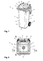
- a waste container 10 is depicted, said waste container being 10 used for picking up and storing bio waste.
- the waste container 10 comprises a container body 11.
- the container body 11 comprises four container walls, a front wall 12, a rear wall 15 and two side walls 13, 14. Furthermore container body 11 comprises a container base 16.
- a travelling gear comprising two wheels 21, 22 is provided in the area of container base 16.
- the container walls 12, 13, 14, 15 extend from the container base 16 to an upper edge 17 of container body 11.
- the upper edge 17 borders or delimits a charging opening 18 of container body 11, by use of which waste can be inserted into the internal space 24 of container body 11, and therefore into waste container 10.
- the container body 11, in particular the charging opening 18 can be closed by a container lid 19 which is arranged to the container body 11 by use of a hinge device 20.
- container lid 19 can be swung open and closed. Since the waste container 10 is used as a waste container for storing bio waste it comprises a number of ventilation apertures 23 as depicted in Figures 4 and 9 .
- the ventilation apertures 23 according to the embodiment are arranged inside the rear wall 15 of waste container 10.
- a shelf device 30 for temporarily storing a waste portion, a paper bag with bio waste for example, a shelf device 30 as depicted in Figures 1 and 6 is provided.
- the shelf device 30 is formed as an arrangement of rods.
- the arrangement comprises seven rods 31, 32, 33, 34, 35, 36, 37.
- the arrangement of rods is formed in a way, that the rods themselves cover a minimum of surface area.
- the rods provide a maximum of support points for supporting the waste portion to be stored.
- the arrangement of rods can provide a curved or looped or strapped or meander shaped configuration.
- the shelf device 30 can be pivot mounted around a pivot axis 39 on at least one container wall of waste container 10.
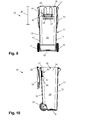
- the shelf device 30 is pivot mounted on the rear wall 15 of container body 11 to allow a pivot movement of the shelf device 30 from an orientation 42 parallel to the rear wall 15, as depicted in Figures 6 to 10 , into an orientation 41 perpendicular or almost perpendicular to the rear wall 15, as depicted in Figures 1 to 5 .
- An orientation 42 parallel to the rear wall 15 is preferably chosen, when the waste container 10 is discharged.
- An orientation 41 perpendicular, which is particularly a 90 degree orientation, or almost perpendicular to the rear wall 15 is preferably chosen, when the shelf device 30 is ready or in use for picking up a waste portion 50 as depicted in Figure 4 .
- the shelf device 30 is arranged inside the container body 11 and therefore, inside the waste container 10.
- the shelf device 30 is adapted to pick up a waste portion 50, as evident from Figure 4 , a waste bag for example, and then when coming with the next waste portion, drop the waste portion 50 stored on the shelf device 30 into the internal space 24 of container body 11 and place the next waste portion on the shelf device 30.
- the shelf device 30 can be arranged in a way that is swings against the rear wall 15, as depicted in Figures 6 to 10 when the waste container 10 is discharged. Once the waste container 10 has been replaced on the ground after the discharge procedure has been finished, the shelf device 30 can swing into a position where it can pick up a waste portion again, as evident from Figures 1 to 5 .
- the shelf device 30 is arranged on the rear wall 15 in the area or vicinity of the ventilation apertures 23.
- the shelf device 30 is mounted on the rear wall 15 by use of those ventilation apertures 23, for example via a clips connection or a screw connection.
- the shelf device 30 is arranged on the rear wall 15 in the upper section 40 of rear wall 15.
- the upper section 40 can be the upper half or the upper third or the upper quarter of the rear wall 15 for example.
- the upper section 40 is defined from the container base 16 in direction of the upper edge 17 of the rear wall 15.
Landscapes
- Engineering & Computer Science (AREA)
- Mechanical Engineering (AREA)
- Refuse Receptacles (AREA)
Priority Applications (2)
| Application Number | Priority Date | Filing Date | Title |
|---|---|---|---|
| DK11174718.4T DK2548820T3 (en) | 2011-07-20 | 2011-07-20 | waste container |
| EP11174718.4A EP2548820B1 (de) | 2011-07-20 | 2011-07-20 | Müllbehälter |
Applications Claiming Priority (1)
| Application Number | Priority Date | Filing Date | Title |
|---|---|---|---|
| EP11174718.4A EP2548820B1 (de) | 2011-07-20 | 2011-07-20 | Müllbehälter |
Publications (2)
| Publication Number | Publication Date |
|---|---|
| EP2548820A1 true EP2548820A1 (de) | 2013-01-23 |
| EP2548820B1 EP2548820B1 (de) | 2017-02-01 |
Family
ID=44675359
Family Applications (1)
| Application Number | Title | Priority Date | Filing Date |
|---|---|---|---|
| EP11174718.4A Active EP2548820B1 (de) | 2011-07-20 | 2011-07-20 | Müllbehälter |
Country Status (2)
| Country | Link |
|---|---|
| EP (1) | EP2548820B1 (de) |
| DK (1) | DK2548820T3 (de) |
Citations (3)
| Publication number | Priority date | Publication date | Assignee | Title |
|---|---|---|---|---|
| EP0386568A1 (de) * | 1989-03-08 | 1990-09-12 | Fritz Schäfer Gesellschaft mit beschränkter Haftung | Müllbehälter mit Durchlüftungssystem |
| US5205433A (en) * | 1991-03-06 | 1993-04-27 | Bartholomaeus Bitsch | Waste-collecting container |
| US5899468A (en) * | 1997-07-02 | 1999-05-04 | Rehrig Pacific Company | Organic waste cart with vented lid |
Family Cites Families (1)
| Publication number | Priority date | Publication date | Assignee | Title |
|---|---|---|---|---|
| DE3628305A1 (de) * | 1985-08-21 | 1987-02-26 | Philipp Maehn | Muelltonne |
-
2011
- 2011-07-20 EP EP11174718.4A patent/EP2548820B1/de active Active
- 2011-07-20 DK DK11174718.4T patent/DK2548820T3/en active
Patent Citations (3)
| Publication number | Priority date | Publication date | Assignee | Title |
|---|---|---|---|---|
| EP0386568A1 (de) * | 1989-03-08 | 1990-09-12 | Fritz Schäfer Gesellschaft mit beschränkter Haftung | Müllbehälter mit Durchlüftungssystem |
| US5205433A (en) * | 1991-03-06 | 1993-04-27 | Bartholomaeus Bitsch | Waste-collecting container |
| US5899468A (en) * | 1997-07-02 | 1999-05-04 | Rehrig Pacific Company | Organic waste cart with vented lid |
Also Published As
| Publication number | Publication date |
|---|---|
| EP2548820B1 (de) | 2017-02-01 |
| DK2548820T3 (en) | 2017-05-08 |
Similar Documents
| Publication | Publication Date | Title |
|---|---|---|
| US6116548A (en) | Apparatus for filling paper lawn refuse bags | |
| US20140076912A1 (en) | Tip resistant refuse tote | |
| US20180312184A1 (en) | Hydration cart | |
| EP2548820A1 (de) | Müllbehälter | |
| CN106612825A (zh) | 一种农家肥施肥拖拉机 | |
| HRP20210306T1 (hr) | Sustav za prikupljanje otpada i odgovarajući spremnik | |
| US6772903B1 (en) | Trash-receiving shopping bag device | |
| WO2004098999A2 (en) | Bag hanging and storage device | |
| CN216567587U (zh) | 自动猫砂盆 | |
| US10166446B2 (en) | Collection container for broken golf tees | |
| EP3162736B1 (de) | Semi-unterirdischer abfallbehälter mit deckel und hebe-auge | |
| EP2325109A1 (de) | Müllbehälter | |
| US20030209549A1 (en) | Garbage can with removable bottom | |
| KR20140035061A (ko) | 스탠드형 쓰레기통 | |
| CN201268491Y (zh) | 具有动平衡门的封闭式垃圾箱 | |
| WO2006071923A2 (en) | Garbage can and support for use with a liner | |
| US20160176631A1 (en) | Mountable receptacle for the temporary placement of lightweight trash or debris | |
| US20050263970A1 (en) | Temporary trash container | |
| CN220906071U (zh) | 一种方便开盖的垃圾箱 | |
| KR200439630Y1 (ko) | 쓰레기통 | |
| RU2639059C2 (ru) | Опорное устройство для пакета с растительными отходами | |
| PL73042Y1 (pl) | Pojemnik na śmieci | |
| CN210913883U (zh) | 一种方便垃圾分类存放的垃圾桶 | |
| KR200322047Y1 (ko) | 쓰레기 수거차 적재함용 덮개 | |
| AU2012100498A4 (en) | Mobile Garbage Bin |
Legal Events
| Date | Code | Title | Description |
|---|---|---|---|
| PUAI | Public reference made under article 153(3) epc to a published international application that has entered the european phase |
Free format text: ORIGINAL CODE: 0009012 |
|
| AK | Designated contracting states |
Kind code of ref document: A1 Designated state(s): AL AT BE BG CH CY CZ DE DK EE ES FI FR GB GR HR HU IE IS IT LI LT LU LV MC MK MT NL NO PL PT RO RS SE SI SK SM TR |
|
| AX | Request for extension of the european patent |
Extension state: BA ME |
|
| 17P | Request for examination filed |
Effective date: 20130701 |
|
| RBV | Designated contracting states (corrected) |
Designated state(s): AL AT BE BG CH CY CZ DE DK EE ES FI FR GB GR HR HU IE IS IT LI LT LU LV MC MK MT NL NO PL PT RO RS SE SI SK SM TR |
|
| 17Q | First examination report despatched |
Effective date: 20130819 |
|
| GRAP | Despatch of communication of intention to grant a patent |
Free format text: ORIGINAL CODE: EPIDOSNIGR1 |
|
| INTG | Intention to grant announced |
Effective date: 20160825 |
|
| GRAS | Grant fee paid |
Free format text: ORIGINAL CODE: EPIDOSNIGR3 |
|
| GRAA | (expected) grant |
Free format text: ORIGINAL CODE: 0009210 |
|
| AK | Designated contracting states |
Kind code of ref document: B1 Designated state(s): AL AT BE BG CH CY CZ DE DK EE ES FI FR GB GR HR HU IE IS IT LI LT LU LV MC MK MT NL NO PL PT RO RS SE SI SK SM TR |
|
| REG | Reference to a national code |
Ref country code: GB Ref legal event code: FG4D |
|
| REG | Reference to a national code |
Ref country code: CH Ref legal event code: EP Ref country code: AT Ref legal event code: REF Ref document number: 865371 Country of ref document: AT Kind code of ref document: T Effective date: 20170215 |
|
| REG | Reference to a national code |
Ref country code: IE Ref legal event code: FG4D |
|
| REG | Reference to a national code |
Ref country code: DE Ref legal event code: R096 Ref document number: 602011034772 Country of ref document: DE |
|
| RAP2 | Party data changed (patent owner data changed or rights of a patent transferred) |
Owner name: ESE WORLD B.V. |
|
| REG | Reference to a national code |
Ref country code: DK Ref legal event code: T3 Effective date: 20170504 |
|
| REG | Reference to a national code |
Ref country code: SE Ref legal event code: TRGR |
|
| REG | Reference to a national code |
Ref country code: NO Ref legal event code: T2 Effective date: 20170201 |
|
| REG | Reference to a national code |
Ref country code: NL Ref legal event code: MP Effective date: 20170201 |
|
| REG | Reference to a national code |
Ref country code: LT Ref legal event code: MG4D |
|
| REG | Reference to a national code |
Ref country code: AT Ref legal event code: MK05 Ref document number: 865371 Country of ref document: AT Kind code of ref document: T Effective date: 20170201 |
|
| REG | Reference to a national code |
Ref country code: FR Ref legal event code: PLFP Year of fee payment: 7 |
|
| PG25 | Lapsed in a contracting state [announced via postgrant information from national office to epo] |
Ref country code: IS Free format text: LAPSE BECAUSE OF FAILURE TO SUBMIT A TRANSLATION OF THE DESCRIPTION OR TO PAY THE FEE WITHIN THE PRESCRIBED TIME-LIMIT Effective date: 20170601 Ref country code: LT Free format text: LAPSE BECAUSE OF FAILURE TO SUBMIT A TRANSLATION OF THE DESCRIPTION OR TO PAY THE FEE WITHIN THE PRESCRIBED TIME-LIMIT Effective date: 20170201 Ref country code: HR Free format text: LAPSE BECAUSE OF FAILURE TO SUBMIT A TRANSLATION OF THE DESCRIPTION OR TO PAY THE FEE WITHIN THE PRESCRIBED TIME-LIMIT Effective date: 20170201 Ref country code: GR Free format text: LAPSE BECAUSE OF FAILURE TO SUBMIT A TRANSLATION OF THE DESCRIPTION OR TO PAY THE FEE WITHIN THE PRESCRIBED TIME-LIMIT Effective date: 20170502 |
|
| PG25 | Lapsed in a contracting state [announced via postgrant information from national office to epo] |
Ref country code: PL Free format text: LAPSE BECAUSE OF FAILURE TO SUBMIT A TRANSLATION OF THE DESCRIPTION OR TO PAY THE FEE WITHIN THE PRESCRIBED TIME-LIMIT Effective date: 20170201 Ref country code: LV Free format text: LAPSE BECAUSE OF FAILURE TO SUBMIT A TRANSLATION OF THE DESCRIPTION OR TO PAY THE FEE WITHIN THE PRESCRIBED TIME-LIMIT Effective date: 20170201 Ref country code: NL Free format text: LAPSE BECAUSE OF FAILURE TO SUBMIT A TRANSLATION OF THE DESCRIPTION OR TO PAY THE FEE WITHIN THE PRESCRIBED TIME-LIMIT Effective date: 20170201 Ref country code: ES Free format text: LAPSE BECAUSE OF FAILURE TO SUBMIT A TRANSLATION OF THE DESCRIPTION OR TO PAY THE FEE WITHIN THE PRESCRIBED TIME-LIMIT Effective date: 20170201 Ref country code: PT Free format text: LAPSE BECAUSE OF FAILURE TO SUBMIT A TRANSLATION OF THE DESCRIPTION OR TO PAY THE FEE WITHIN THE PRESCRIBED TIME-LIMIT Effective date: 20170601 Ref country code: RS Free format text: LAPSE BECAUSE OF FAILURE TO SUBMIT A TRANSLATION OF THE DESCRIPTION OR TO PAY THE FEE WITHIN THE PRESCRIBED TIME-LIMIT Effective date: 20170201 Ref country code: BG Free format text: LAPSE BECAUSE OF FAILURE TO SUBMIT A TRANSLATION OF THE DESCRIPTION OR TO PAY THE FEE WITHIN THE PRESCRIBED TIME-LIMIT Effective date: 20170501 Ref country code: AT Free format text: LAPSE BECAUSE OF FAILURE TO SUBMIT A TRANSLATION OF THE DESCRIPTION OR TO PAY THE FEE WITHIN THE PRESCRIBED TIME-LIMIT Effective date: 20170201 |
|
| PG25 | Lapsed in a contracting state [announced via postgrant information from national office to epo] |
Ref country code: SK Free format text: LAPSE BECAUSE OF FAILURE TO SUBMIT A TRANSLATION OF THE DESCRIPTION OR TO PAY THE FEE WITHIN THE PRESCRIBED TIME-LIMIT Effective date: 20170201 Ref country code: EE Free format text: LAPSE BECAUSE OF FAILURE TO SUBMIT A TRANSLATION OF THE DESCRIPTION OR TO PAY THE FEE WITHIN THE PRESCRIBED TIME-LIMIT Effective date: 20170201 Ref country code: CZ Free format text: LAPSE BECAUSE OF FAILURE TO SUBMIT A TRANSLATION OF THE DESCRIPTION OR TO PAY THE FEE WITHIN THE PRESCRIBED TIME-LIMIT Effective date: 20170201 Ref country code: RO Free format text: LAPSE BECAUSE OF FAILURE TO SUBMIT A TRANSLATION OF THE DESCRIPTION OR TO PAY THE FEE WITHIN THE PRESCRIBED TIME-LIMIT Effective date: 20170201 Ref country code: IT Free format text: LAPSE BECAUSE OF FAILURE TO SUBMIT A TRANSLATION OF THE DESCRIPTION OR TO PAY THE FEE WITHIN THE PRESCRIBED TIME-LIMIT Effective date: 20170201 |
|
| REG | Reference to a national code |
Ref country code: DE Ref legal event code: R097 Ref document number: 602011034772 Country of ref document: DE |
|
| PG25 | Lapsed in a contracting state [announced via postgrant information from national office to epo] |
Ref country code: SM Free format text: LAPSE BECAUSE OF FAILURE TO SUBMIT A TRANSLATION OF THE DESCRIPTION OR TO PAY THE FEE WITHIN THE PRESCRIBED TIME-LIMIT Effective date: 20170201 |
|
| PLBE | No opposition filed within time limit |
Free format text: ORIGINAL CODE: 0009261 |
|
| STAA | Information on the status of an ep patent application or granted ep patent |
Free format text: STATUS: NO OPPOSITION FILED WITHIN TIME LIMIT |
|
| 26N | No opposition filed |
Effective date: 20171103 |
|
| PG25 | Lapsed in a contracting state [announced via postgrant information from national office to epo] |
Ref country code: SI Free format text: LAPSE BECAUSE OF FAILURE TO SUBMIT A TRANSLATION OF THE DESCRIPTION OR TO PAY THE FEE WITHIN THE PRESCRIBED TIME-LIMIT Effective date: 20170201 |
|
| REG | Reference to a national code |
Ref country code: CH Ref legal event code: PL |
|
| GBPC | Gb: european patent ceased through non-payment of renewal fee |
Effective date: 20170720 |
|
| REG | Reference to a national code |
Ref country code: IE Ref legal event code: MM4A |
|
| PG25 | Lapsed in a contracting state [announced via postgrant information from national office to epo] |
Ref country code: CH Free format text: LAPSE BECAUSE OF NON-PAYMENT OF DUE FEES Effective date: 20170731 Ref country code: IE Free format text: LAPSE BECAUSE OF NON-PAYMENT OF DUE FEES Effective date: 20170720 Ref country code: LI Free format text: LAPSE BECAUSE OF NON-PAYMENT OF DUE FEES Effective date: 20170731 Ref country code: GB Free format text: LAPSE BECAUSE OF NON-PAYMENT OF DUE FEES Effective date: 20170720 |
|
| REG | Reference to a national code |
Ref country code: BE Ref legal event code: MM Effective date: 20170731 |
|
| PG25 | Lapsed in a contracting state [announced via postgrant information from national office to epo] |
Ref country code: LU Free format text: LAPSE BECAUSE OF NON-PAYMENT OF DUE FEES Effective date: 20170720 |
|
| REG | Reference to a national code |
Ref country code: FR Ref legal event code: PLFP Year of fee payment: 8 |
|
| PG25 | Lapsed in a contracting state [announced via postgrant information from national office to epo] |
Ref country code: BE Free format text: LAPSE BECAUSE OF NON-PAYMENT OF DUE FEES Effective date: 20170731 |
|
| PG25 | Lapsed in a contracting state [announced via postgrant information from national office to epo] |
Ref country code: MT Free format text: LAPSE BECAUSE OF NON-PAYMENT OF DUE FEES Effective date: 20170720 |
|
| PG25 | Lapsed in a contracting state [announced via postgrant information from national office to epo] |
Ref country code: HU Free format text: LAPSE BECAUSE OF FAILURE TO SUBMIT A TRANSLATION OF THE DESCRIPTION OR TO PAY THE FEE WITHIN THE PRESCRIBED TIME-LIMIT; INVALID AB INITIO Effective date: 20110720 Ref country code: MC Free format text: LAPSE BECAUSE OF FAILURE TO SUBMIT A TRANSLATION OF THE DESCRIPTION OR TO PAY THE FEE WITHIN THE PRESCRIBED TIME-LIMIT Effective date: 20170201 |
|
| PG25 | Lapsed in a contracting state [announced via postgrant information from national office to epo] |
Ref country code: CY Free format text: LAPSE BECAUSE OF NON-PAYMENT OF DUE FEES Effective date: 20170201 |
|
| PGFP | Annual fee paid to national office [announced via postgrant information from national office to epo] |
Ref country code: FR Payment date: 20190724 Year of fee payment: 9 |
|
| PG25 | Lapsed in a contracting state [announced via postgrant information from national office to epo] |
Ref country code: MK Free format text: LAPSE BECAUSE OF FAILURE TO SUBMIT A TRANSLATION OF THE DESCRIPTION OR TO PAY THE FEE WITHIN THE PRESCRIBED TIME-LIMIT Effective date: 20170201 |
|
| PG25 | Lapsed in a contracting state [announced via postgrant information from national office to epo] |
Ref country code: TR Free format text: LAPSE BECAUSE OF FAILURE TO SUBMIT A TRANSLATION OF THE DESCRIPTION OR TO PAY THE FEE WITHIN THE PRESCRIBED TIME-LIMIT Effective date: 20170201 |
|
| REG | Reference to a national code |
Ref country code: DE Ref legal event code: R082 Ref document number: 602011034772 Country of ref document: DE Representative=s name: MUELLER, THOMAS, DIPL.-ING., DE |
|
| PG25 | Lapsed in a contracting state [announced via postgrant information from national office to epo] |
Ref country code: AL Free format text: LAPSE BECAUSE OF FAILURE TO SUBMIT A TRANSLATION OF THE DESCRIPTION OR TO PAY THE FEE WITHIN THE PRESCRIBED TIME-LIMIT Effective date: 20170201 |
|
| PG25 | Lapsed in a contracting state [announced via postgrant information from national office to epo] |
Ref country code: FR Free format text: LAPSE BECAUSE OF NON-PAYMENT OF DUE FEES Effective date: 20200731 |
|
| PGFP | Annual fee paid to national office [announced via postgrant information from national office to epo] |
Ref country code: DK Payment date: 20210721 Year of fee payment: 11 Ref country code: DE Payment date: 20210721 Year of fee payment: 11 |
|
| REG | Reference to a national code |
Ref country code: DE Ref legal event code: R119 Ref document number: 602011034772 Country of ref document: DE |
|
| REG | Reference to a national code |
Ref country code: DK Ref legal event code: EBP Effective date: 20220731 |
|
| PG25 | Lapsed in a contracting state [announced via postgrant information from national office to epo] |
Ref country code: DE Free format text: LAPSE BECAUSE OF NON-PAYMENT OF DUE FEES Effective date: 20230201 |
|
| PG25 | Lapsed in a contracting state [announced via postgrant information from national office to epo] |
Ref country code: DK Free format text: LAPSE BECAUSE OF NON-PAYMENT OF DUE FEES Effective date: 20220731 |
|
| PGFP | Annual fee paid to national office [announced via postgrant information from national office to epo] |
Ref country code: FI Payment date: 20250722 Year of fee payment: 15 |
|
| PGFP | Annual fee paid to national office [announced via postgrant information from national office to epo] |
Ref country code: NO Payment date: 20250722 Year of fee payment: 15 |
|
| PGFP | Annual fee paid to national office [announced via postgrant information from national office to epo] |
Ref country code: SE Payment date: 20250723 Year of fee payment: 15 |