EP2548833B1 - Längsstoß - Google Patents
Längsstoß Download PDFInfo
- Publication number
- EP2548833B1 EP2548833B1 EP12382249.6A EP12382249A EP2548833B1 EP 2548833 B1 EP2548833 B1 EP 2548833B1 EP 12382249 A EP12382249 A EP 12382249A EP 2548833 B1 EP2548833 B1 EP 2548833B1
- Authority
- EP
- European Patent Office
- Prior art keywords
- passage
- longitudinal joint
- transverse slats
- slats
- attached
- Prior art date
- Legal status (The legal status is an assumption and is not a legal conclusion. Google has not performed a legal analysis and makes no representation as to the accuracy of the status listed.)
- Active
Links
Images



Classifications
-
- B—PERFORMING OPERATIONS; TRANSPORTING
- B66—HOISTING; LIFTING; HAULING
- B66B—ELEVATORS; ESCALATORS OR MOVING WALKWAYS
- B66B21/00—Kinds or types of escalators or moving walkways
- B66B21/10—Moving walkways
-
- B—PERFORMING OPERATIONS; TRANSPORTING
- B66—HOISTING; LIFTING; HAULING
- B66B—ELEVATORS; ESCALATORS OR MOVING WALKWAYS
- B66B23/00—Component parts of escalators or moving walkways
-
- B—PERFORMING OPERATIONS; TRANSPORTING
- B66—HOISTING; LIFTING; HAULING
- B66B—ELEVATORS; ESCALATORS OR MOVING WALKWAYS
- B66B23/00—Component parts of escalators or moving walkways
- B66B23/08—Carrying surfaces
-
- B—PERFORMING OPERATIONS; TRANSPORTING
- B66—HOISTING; LIFTING; HAULING
- B66B—ELEVATORS; ESCALATORS OR MOVING WALKWAYS
- B66B23/00—Component parts of escalators or moving walkways
- B66B23/16—Means allowing tensioning of the endless member
-
- B—PERFORMING OPERATIONS; TRANSPORTING
- B66—HOISTING; LIFTING; HAULING
- B66B—ELEVATORS; ESCALATORS OR MOVING WALKWAYS
- B66B31/00—Accessories for escalators, or moving walkways, e.g. for sterilising or cleaning
-
- Y—GENERAL TAGGING OF NEW TECHNOLOGICAL DEVELOPMENTS; GENERAL TAGGING OF CROSS-SECTIONAL TECHNOLOGIES SPANNING OVER SEVERAL SECTIONS OF THE IPC; TECHNICAL SUBJECTS COVERED BY FORMER USPC CROSS-REFERENCE ART COLLECTIONS [XRACs] AND DIGESTS
- Y10—TECHNICAL SUBJECTS COVERED BY FORMER USPC
- Y10T—TECHNICAL SUBJECTS COVERED BY FORMER US CLASSIFICATION
- Y10T403/00—Joints and connections
- Y10T403/32—Articulated members
- Y10T403/32008—Plural distinct articulation axes
- Y10T403/32016—Three or more parallel axes
Definitions
- the present invention relates to longitudinal joints for forming surfaces the purpose of which is to allow varying the distance between two fixed adjacent passage surfaces, maintaining the continuity between both and allowing use as a treadable surface by users.
- the variation of the distance between the two adjacent passage surfaces allowed by the longitudinal joint is short, and it will be due to certain reasons such as temperature and operating variations, manufacturing or assembly tolerances, or elongation of components relating to the adjacent passage surfaces due to use.
- patent US2958083A An example of application can be seen in patent US2958083A , where this concept is used for covering a swimming pool.
- Other patents such as WO9708408A try to solve the mechanism which allows covering or removing covers using this concept or covers of other types.
- Patent US4341253A uses an equivalent system for covering a vehicle service pit, and patent US1707287A uses a similar concept for forming a vertical door serving as protection against fire.
- Patent US2173900A applies a cover formed by slats for protecting an escalator, said cover not forming part of the machine itself.
- patent JP8188365A describes various solutions of systems for opening maintenance pit covers for reducing the effort needed.
- the present invention seeks to apply the blind concept to form a longitudinal joint between two fixed pit covers the relative distance of which will vary due to different reasons and without applying any manually or mechanically operated mechanism and forming a treadable continuous surface for the users of escalators or moving walkways.
- a fixed relative position between the overturn position of the steps or pallets and the combs is used, whether it is through the traditional step or pallet chain or when in its place the steps or pallets themselves are attached to one another forming a continuous band.
- said step or pallet chain or the band formed by them requires being tensed, its position is modified with respect to the fixed part, therefore if the position of the combs is maintained with respect to the band of steps or pallets it is necessary to have a surface which allows varying the length between said adjacent surfaces.
- EP 2177469 A1 discloses a longitudinal joint according to the preamble of claim 1.
- the present invention solves the problems existing in the state of the art by means of a longitudinal joint of the type forming a surface usable as a passage between a first passage surface and a second passage surface adjacent to one another, and usable as walking user passage, the distance between the first surface and the second surface in the longitudinal direction being variable.
- Said surface must have the same consistency as the adjacent passage surfaces and serve as support for user passage.
- the longitudinal joint has a plurality of transverse slats which are attached to one another forming a substantially planar upper surface.
- Each of the transverse slats of the longitudinal joint is attached to the contiguous transverse slats by a pivot point with respect to which said transverse slats can rotate, maintaining the continuity of the surface of the longitudinal joint.
- the longitudinal joint additionally has intermediate surfaces configured for supporting the transverse slats, these intermediate surfaces being attached to the adjacent passage surfaces.
- the longitudinal joint additionally comprises a first intermediate surface which is attached to the first passage surface, and a second intermediate surface which is attached to the second passage surface, configured for supporting the transverse slats (4). At least part of the second intermediate surface rests on the first intermediate surface, the support area between both surfaces being variable depending on the distance between the first passage surface and the second passage surface.
- the transverse slats can preferably rest on first support surfaces supported on the first intermediate surface, and on second support surfaces supported on the second intermediate surface, the first support surfaces and the second support surfaces preferably being transversely alternated.
- transverse slats additionally rest on curved support surfaces which are attached directly to the first intermediate surface, and said first passage surface has an inclined lower surface at its end such that a certain number of transverse slats are hidden under this first passage surface, below the level of the upper surface of the longitudinal joint, by means of the relative rotation of the slats to one another with respect to the pivot point, depending on the distance existing between said first passage surface and the second passage surface. Therefore, when the distance between adjacent passage surfaces is the maximum considered in the design thereof, there will be a small number of slats hidden under the first passage surface, while when said distance is minimum there will be a greater number of slats hidden under the first passage surface and therefore a smaller number of visible slats.
- the inclined lower surface of the first passage surface particularly rests on the transverse slats which are hidden under it by means of at least one additional support element, giving greater consistency to the transition between the passage surfaces.
- All the surfaces and supports have sufficient structural consistency and resistance and suitable non-slip properties for allowing users to pass on them.
- both the slats and the support surfaces on which the slats are supported are made of a material the properties of which allow friction which occurs when the distance between the adjacent passage surfaces varies without deteriorating.
- the transverse slats of the longitudinal joint object of the invention preferably have a protective element at each of their ends protecting said transverse slats and the fixed structure in which this longitudinal joint is arranged from friction.
- a protective element at each of their ends protecting said transverse slats and the fixed structure in which this longitudinal joint is arranged from friction.
- the present invention has tensing means connected to the transverse slats which are hidden under the first passage surface. These tensing means, either by means of placing weights, a spring or other similar means, make the tension help to assure stability and movements of the slats are thereby prevented, whether such movements of the slats are transverse to one another, longitudinal movements which modify the amount of usable surface in the cover when there is no variation of the distance between the adjacent passage surfaces, or vertical movements which can generate noises when being used by users.
- One of the preferred applications for which the present invention can be used is to serve as a treadable surface for users of escalators and moving walkways, in which the position of the comb plate experiences a relative movement with respect to the fixed pit cover, due for example to it using a system of combs in which the position between the overturn of the steps or pallets and said combs must be fixed and where the step or pallet chain or the band formed by them requires being tensed.
- the object of the present invention is a longitudinal joint of the type forming a surface usable as a passage between a first passage surface 2 and a second passage surface 3, which are adjacent to one another, and they are used as walking user passage, the distance between both surfaces 2,3 in the longitudinal direction being variable.
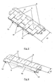
- the longitudinal joint 1 is formed by a plurality of transverse slats 4 attached to one another which have a geometry such that they form a substantially planar upper surface 5.
- Each of the transverse slats 4 is attached to the transverse slats 4 contiguous to it by a pivot point 6 with respect to which said transverse slats 4 can rotate and preserve the continuity of the surface of the longitudinal joint.
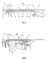
- the longitudinal joint additionally has a first intermediate surface 10 integrally attached to the first passage surface 2 by means of fastenings 14, and a second intermediate surface 13 integrally attached to the second passage surface 3 by means of fastenings 15, configured for supporting the transverse slats 4.
- the transverse slats 4 rest on first support surfaces 9, which are supported on the first intermediate surface 10 and on second support surfaces 12, which are supported on the second intermediate surface 13. Furthermore, as shown in Figures 5 and 6 , the first support surfaces 9 and the second support surfaces 12 are preferably transversely alternated.
- transverse slats 4 rest on curved support surfaces 8 which are attached directly to the first intermediate surface 10.
- the material of the support surfaces 8,9,12 allows friction which occurs with respect to the lower surface of the slats 4 when the distance between the adjacent support surfaces 2,3 varies without deteriorating.
- Figures 7 to 10 show that the first passage surface 2 has an inclined lower surface 16 at its end such that a certain number of transverse slats 4 are hidden under said first passage surface 2, below the level of the upper surface 5 of the longitudinal joint 1, this being achieved by means of the relative rotation of the slats 4 to one another with respect to the pivot point 6, depending on the distance existing between the first passage surface 2 and the second passage surface 3.
- the inclined lower surface 16 of the first passage surface 2 preferably rests on the transverse slats 4 which are hidden under it by means of at least one additional support element 17, as seen in the figures, giving greater consistency to the transition between adjacent support surfaces 2,3.
- the transverse slats 4 comprise a cap or protective element 11 at each of their ends protecting said transverse slats 4 and the fixed structure 7 in which the longitudinal joint 1 is arranged from friction.
- This protective element 11 can be seen in Figures 3 and 4 .
- the longitudinal joint has tensing means 18,19 connected to the transverse slats 4 which are hidden under the first passage surface 2.
- the slats 4 which are hidden vertically below the first support surface 2 can preferably have a tensing system by means of placing one or several springs 18, one or several weights 19 or other similar systems, such that said tension helps to assure stability, and movements of the slats 4 are thereby prevented, whether such movements are transverse, longitudinal, or vertical movements.
Landscapes
- Building Environments (AREA)
- Blinds (AREA)
- Escalators And Moving Walkways (AREA)
- Steps, Ramps, And Handrails (AREA)
- Operating, Guiding And Securing Of Roll- Type Closing Members (AREA)
Claims (6)
- Längsfuge nach der Art, die eine Fläche bildet, die als ein Gang zwischen einer ersten Gangfläche (2) und einer zweiten Gangfläche (3), die zueinander benachbart sind, verwendbar ist sowie als Gang für einen zu Fuß gehenden Benutzer verwendbar ist, wobei der Abstand zwischen beiden Flächen (2, 3) in der Längsrichtung variabel ist, wobei die Längsfuge (1)- eine Vielzahl von Querleisten (4) umfasst, die aneinander angebracht sind und eine im Wesentlichen planare obere Fläche (5) haben,- wobei jede der Querleisten (4) an den angrenzenden Querleisten (4) über einen Drehpunkt (6) angebracht ist, bezüglich dessen sich die Querleisten (4) unter Beibehaltung der Durchgängigkeit der Fläche der Längsfuge (1) drehen können,- wobei die erste Gangfläche (2) eine geneigte untere Fläche (16) an ihrem Ende umfasst,
wobei eine gewisse Anzahl von Querleisten (4) unter der ersten Gangfläche (2) unter dem Niveau der oberen Fläche (5) der Längsfuge (1) mittels der Relativdrehung der Leisten (4) zueinander bezüglich des Drehpunkts (6) versteckt sind, je nach dem Abstand, der zwischen der ersten Gangfläche (2) und der zweiten Gangfläche (3) vorliegt,
dadurch gekennzeichnet, dass
die Längsfuge zusätzlich eine erste Zwischenfläche (10), die an der ersten Gangfläche (2) angebracht ist, und eine zweite Zwischenfläche (13), die an der zweiten Gangfläche (3) angebracht ist, umfasst, die zum Stützen der Querleisten (4) ausgestaltet sind, wobei mindestens ein Teil der zweiten Zwischenfläche (13) auf der ersten Zwischenfläche (10) ruht, wobei die Stützfläche zwischen beiden Flächen (13, 10) je nach dem Abstand zwischen der ersten Gangfläche (2) und der zweiten Gangfläche (3) variabel ist, und- dass die Querleisten (4) zusätzlich auf gekrümmten Stützflächen (8) ruhen, die direkt an der ersten Zwischenfläche (10) angebracht sind, wobei die erste Zwischenfläche (10) an der ersten Gangfläche (2) angebracht ist. - Längsfuge nach Anspruch 1, dadurch gekennzeichnet, dass die Querleisten (4) auf ersten Stützflächen (9) ruhen, die auf der ersten Zwischenfläche (10) gestützt sind, und auf zweiten Stützflächen (12), die auf der zweiten Zwischenfläche (13) gestützt sind.
- Längsfuge nach dem vorhergehenden Anspruch, dadurch gekennzeichnet, dass sich die ersten Stützflächen (9) und die zweiten Stützflächen (12) quer abwechseln.
- Längsfuge nach einem der vorhergehenden Ansprüche, dadurch gekennzeichnet, dass die geneigte untere Fläche (16) der ersten Gangfläche (2) auf den Querleisten (4) ruht, die unter ihr versteckt sind, mittels mindestens eines zusätzlichen Stützelements (17).
- Längsfuge nach einem der vorhergehenden Ansprüche, dadurch gekennzeichnet, dass die Querleisten (4) ein Schutzelement (11) an jedem ihrer Enden umfassen, das die Querleisten (4) und die festgelegte Struktur (7), in der die Längsfuge (1) angeordnet ist, vor Reibung schützt.
- Längsfuge nach einem der vorhergehenden Ansprüche, dadurch gekennzeichnet, dass sie Spannmittel (18, 19) umfasst, die mit den Querleisten (4) verbunden sind, die unter der ersten Gangfläche (2) versteckt sind.
Applications Claiming Priority (1)
| Application Number | Priority Date | Filing Date | Title |
|---|---|---|---|
| ES201131237A ES2368327B1 (es) | 2011-07-20 | 2011-07-20 | Junta longitudinal. |
Publications (2)
| Publication Number | Publication Date |
|---|---|
| EP2548833A1 EP2548833A1 (de) | 2013-01-23 |
| EP2548833B1 true EP2548833B1 (de) | 2021-09-01 |
Family
ID=44862180
Family Applications (1)
| Application Number | Title | Priority Date | Filing Date |
|---|---|---|---|
| EP12382249.6A Active EP2548833B1 (de) | 2011-07-20 | 2012-06-25 | Längsstoß |
Country Status (7)
| Country | Link |
|---|---|
| US (1) | US8567591B2 (de) |
| EP (1) | EP2548833B1 (de) |
| JP (1) | JP5864377B2 (de) |
| KR (1) | KR101959819B1 (de) |
| CN (1) | CN102887423B (de) |
| BR (1) | BR102012018117A2 (de) |
| ES (2) | ES2368327B1 (de) |
Families Citing this family (19)
| Publication number | Priority date | Publication date | Assignee | Title |
|---|---|---|---|---|
| ITMI20110642A1 (it) * | 2011-04-14 | 2012-10-15 | Rexnord Marbett Srl | Disposizione di moduli di scorrimento |
| FR2975420B1 (fr) * | 2011-05-17 | 2014-07-18 | R Pi | Dispositif d'obturation au moins partielle d'une cavite ouverte par le dessus |
| CN103033032B (zh) * | 2013-01-15 | 2015-02-18 | 上海东富龙科技股份有限公司 | 一种冻干机的自动进出料装置 |
| US10233035B2 (en) | 2014-04-10 | 2019-03-19 | Flexible Steel Lacing Company | Conveyor transfer guards |
| US9452896B2 (en) * | 2014-09-25 | 2016-09-27 | Laitram, L.L.C. | Pop-up conveyor transfer system |
| TWM513555U (zh) * | 2015-08-25 | 2015-12-01 | 富世達股份有限公司 | 可應用在軟性顯示屏幕之聯結裝置 |
| JP6169664B2 (ja) * | 2015-10-02 | 2017-07-26 | 日昭建材工業株式会社 | 床のみ込み式エキスパンションジョイントの段差目地解消装置 |
| TWM544508U (zh) * | 2015-12-01 | 2017-07-01 | 耐克創新有限合夥公司 | 在製造製程中的材料張緊系統 |
| CN108367868B (zh) | 2015-12-09 | 2020-10-16 | 莱特拉姆有限责任公司 | 输送机传送组件 |
| EP3390264B1 (de) * | 2015-12-17 | 2020-02-12 | Inventio AG | Bodenabdeckung einer personenfördereinrichtung |
| CN106144869A (zh) * | 2016-08-24 | 2016-11-23 | 苏州新达电扶梯部件有限公司 | 一种带铰链的扶梯后盖板结构 |
| KR20240128141A (ko) * | 2017-04-10 | 2024-08-23 | 후렉크시불스티일레이싱캄파니 | 이송 가드 시스템, 이송 시스템 및 이송 시스템의 설치 방법 |
| US10427891B2 (en) * | 2017-06-29 | 2019-10-01 | Flexible Steel Lacing Company | Transfer guard system and mount thereof |
| US10807809B1 (en) * | 2020-01-07 | 2020-10-20 | Honda Motor Co., Ltd. | End plate for conveyor belt |
| CA3193208A1 (en) | 2020-09-22 | 2022-03-31 | Flexible Steel Lacing Company | Roller conveyor gap blocker |
| JP2024533604A (ja) | 2021-09-24 | 2024-09-12 | フレキシブル・スチール・レーシング・カンパニー | ローラコンベヤ間隙遮断器 |
| EP4486670A4 (de) | 2022-03-03 | 2026-03-04 | Flexible Steel Lacing Co | Fördererspaltblocker |
| USD1064492S1 (en) | 2022-03-04 | 2025-02-25 | Flexible Steel Lacing Company | Conveyor gap blocker |
| CN220333990U (zh) | 2022-03-25 | 2024-01-12 | 弹性钢接头公司 | 传输防护构件和传输防护系统 |
Family Cites Families (29)
| Publication number | Priority date | Publication date | Assignee | Title |
|---|---|---|---|---|
| US1707287A (en) | 1926-08-30 | 1929-04-02 | Sudzki Tomitaro | Fireproof shutter |
| US2173900A (en) * | 1938-06-25 | 1939-09-26 | Otis Elevator Co | Operating mechanism for closures for moving stairway wellway openings |
| US2624444A (en) * | 1950-02-25 | 1953-01-06 | Jampol Company Inc | Apparatus for free pivoting transfer rollers |
| US2958083A (en) | 1955-09-19 | 1960-11-01 | Nemoede | Swimming pool safety device |
| US4037714A (en) * | 1976-07-21 | 1977-07-26 | Centri-Spray Corporation | Reciprocating conveyor |
| US4341253A (en) * | 1979-11-12 | 1982-07-27 | Anton Eyerle | Cover arrangement for servicing holes |
| JPS5931602B2 (ja) * | 1980-04-04 | 1984-08-03 | シヨ−ボンド建設株式会社 | 橋梁伸縮継手 |
| JPH0745316B2 (ja) * | 1988-11-29 | 1995-05-17 | 株式会社日立ビルシステムサービス | エスカレータ踏段の養生装置 |
| ATE87685T1 (de) * | 1989-02-06 | 1993-04-15 | Robert Warthmann | Rollverschluss-fahrbahnuebergang, insbesondere fuer dilatationsfugen von bruecken. |
| FR2724620B1 (fr) * | 1994-09-16 | 1997-01-10 | Lohr Ind | Passerelle deformable entre deux plans de chargement portes par des chassis successifs notamment ferroviaires |
| JPH08188365A (ja) * | 1994-12-28 | 1996-07-23 | Mitsubishi Denki Bill Techno Service Kk | マンホールの蓋開閉装置 |
| JPH08231167A (ja) * | 1995-02-24 | 1996-09-10 | Hitachi Ltd | 乗客コンベアのステップ |
| JP3572114B2 (ja) * | 1995-04-04 | 2004-09-29 | 株式会社日立製作所 | 可変速型乗客コンベア |
| US5799342A (en) | 1995-08-29 | 1998-09-01 | Last; Harry J. | Manual cover drive for swimming pools |
| JPH09124263A (ja) * | 1995-11-02 | 1997-05-13 | Hitachi Ltd | 乗客コンベアの踏段 |
| FR2747664B1 (fr) * | 1996-04-23 | 1998-06-05 | Mediterranee Const Ind | Dispositif de transfert, en particulier pour pietons, entre deux elements de transport disposes en prolongement l'un de l'autre et transporteur equipe d'un tel dispositif |
| US5605222A (en) * | 1996-04-24 | 1997-02-25 | Illinois Tool Works Inc. | Dual knife edge transfer conveyor |
| MY119352A (en) * | 1997-01-17 | 2005-05-31 | Inventio Ag | Moving walkway for passengers |
| EP0919493A1 (de) * | 1997-11-12 | 1999-06-02 | Rexnord Marbett S.p.A. | Modular strukturierte Platte zur Aufnahme durch einen Förderer zugeführter Produkt |
| JP2000045211A (ja) * | 1998-07-29 | 2000-02-15 | Japan Steel Works Ltd:The | 橋床部間遊間のジョイント構造 |
| DE19850847A1 (de) * | 1998-11-04 | 2000-05-11 | Moessner Druckguswerk Gmbh | Fahrtreppenstufe |
| CN2458268Y (zh) * | 2001-01-09 | 2001-11-07 | 西子电梯集团有限公司 | 自动人行道不锈钢踏板 |
| US6959803B1 (en) * | 2002-12-18 | 2005-11-01 | Span Tech Llc | Self-tensioning conveyor |
| CN201056452Y (zh) * | 2007-03-27 | 2008-05-07 | 广州华工百川科技股份有限公司 | 自动扶梯梯级 |
| US7673732B2 (en) * | 2007-09-28 | 2010-03-09 | Pro Engineering & Manufacturing, Inc. | Transfer plate and method of interfacing to a belt |
| ES2300225B1 (es) * | 2007-11-07 | 2009-08-24 | Thyssenkrupp Elevator (Es/Pbb)Ltd | Pasillo movil. |
| ES2319084B1 (es) * | 2008-10-20 | 2010-03-16 | Thyssenkrupp Elevator Innovation | Junta longitudinal transversal. |
| CN201400511Y (zh) * | 2009-04-23 | 2010-02-10 | 苏州奔一机电有限公司 | 一种自动扶梯踏板 |
| US8210341B2 (en) * | 2009-12-08 | 2012-07-03 | Laitram, L.L.C. | Conveyor transfer system with floating transfer platform |
-
2011
- 2011-07-20 ES ES201131237A patent/ES2368327B1/es active Active
-
2012
- 2012-06-25 EP EP12382249.6A patent/EP2548833B1/de active Active
- 2012-06-25 ES ES12382249T patent/ES2897687T3/es active Active
- 2012-07-16 US US13/550,151 patent/US8567591B2/en active Active
- 2012-07-17 KR KR1020120077719A patent/KR101959819B1/ko active Active
- 2012-07-19 JP JP2012160588A patent/JP5864377B2/ja active Active
- 2012-07-20 BR BRBR102012018117-7A patent/BR102012018117A2/pt not_active Application Discontinuation
- 2012-07-20 CN CN201210252020.9A patent/CN102887423B/zh active Active
Also Published As
| Publication number | Publication date |
|---|---|
| CN102887423B (zh) | 2016-12-21 |
| KR20130011934A (ko) | 2013-01-30 |
| BR102012018117A2 (pt) | 2015-08-04 |
| ES2368327B1 (es) | 2012-09-18 |
| EP2548833A1 (de) | 2013-01-23 |
| KR101959819B1 (ko) | 2019-03-20 |
| US20130022389A1 (en) | 2013-01-24 |
| ES2897687T3 (es) | 2022-03-02 |
| JP2013024029A (ja) | 2013-02-04 |
| ES2368327A1 (es) | 2011-11-16 |
| CN102887423A (zh) | 2013-01-23 |
| US8567591B2 (en) | 2013-10-29 |
| JP5864377B2 (ja) | 2016-02-17 |
Similar Documents
| Publication | Publication Date | Title |
|---|---|---|
| US8567591B2 (en) | Longitudinal joint | |
| JP6389788B2 (ja) | 乗客コンベア | |
| EP2058264A1 (de) | Beweglicher Fahrsteig | |
| EP2239199B1 (de) | Fluggastbrücke | |
| ITPR20090078A1 (it) | Dispositivo antideragliamento per ante di porte di ascensori o elevatori | |
| HK1217220A1 (zh) | 包括不同密度的梯区段的伸缩梯 | |
| KR101821356B1 (ko) | 박판을 지지하는 구조의 교량의 상판 구조체 및 그 시공 방법 | |
| JP4556129B2 (ja) | 落橋防止装置 | |
| JP6166166B2 (ja) | 乗客コンベア | |
| EP3242849A1 (de) | Zugelement für aufzugssystem | |
| JP6539480B2 (ja) | 昇降式ゲート装置 | |
| JP5989379B2 (ja) | 安全柵 | |
| JP6974121B2 (ja) | 可動支柱、ワイヤロープ式防護柵及び橋梁 | |
| US5779028A (en) | Belt having transverse rigidity | |
| EP2374986B1 (de) | Fallschutzvorrichtung für einen ausziehbaren Leitersatz | |
| JP6568031B2 (ja) | 乗客コンベア | |
| JP2014151974A (ja) | 乗客コンベア装置の被覆装置 | |
| JP6352473B1 (ja) | 乗客コンベア | |
| EP3102293B1 (de) | Rauch- oder feuersperre | |
| JP4398715B2 (ja) | 乗客コンベア | |
| EP3775389B1 (de) | Strassenrückhaltesystem mit verbesserter bodenhemmleistung | |
| JP2008297051A (ja) | 乗客コンベア | |
| KR101568846B1 (ko) | 단부 주탑이 구비된 교량의 상부구조 및 이를 이용한 교량의 시공방법 | |
| JP2016148209A (ja) | ロープ連結材 | |
| RS56775B1 (sr) | Sistem za zadržavanje vozila |
Legal Events
| Date | Code | Title | Description |
|---|---|---|---|
| PUAI | Public reference made under article 153(3) epc to a published international application that has entered the european phase |
Free format text: ORIGINAL CODE: 0009012 |
|
| AK | Designated contracting states |
Kind code of ref document: A1 Designated state(s): AL AT BE BG CH CY CZ DE DK EE ES FI FR GB GR HR HU IE IS IT LI LT LU LV MC MK MT NL NO PL PT RO RS SE SI SK SM TR |
|
| AX | Request for extension of the european patent |
Extension state: BA ME |
|
| 17P | Request for examination filed |
Effective date: 20130716 |
|
| RBV | Designated contracting states (corrected) |
Designated state(s): AL AT BE BG CH CY CZ DE DK EE ES FI FR GB GR HR HU IE IS IT LI LT LU LV MC MK MT NL NO PL PT RO RS SE SI SK SM TR |
|
| 17Q | First examination report despatched |
Effective date: 20160624 |
|
| RIN1 | Information on inventor provided before grant (corrected) |
Inventor name: PELLO GARCIA, ALBERTO Inventor name: GONZALEZ ALEMANY, MIGUEL ANGEL Inventor name: DIAZ SORRIBAS, MONICA Inventor name: GONZALEZ PANTIGA, JUAN DOMINGO |
|
| STAA | Information on the status of an ep patent application or granted ep patent |
Free format text: STATUS: EXAMINATION IS IN PROGRESS |
|
| GRAP | Despatch of communication of intention to grant a patent |
Free format text: ORIGINAL CODE: EPIDOSNIGR1 |
|
| STAA | Information on the status of an ep patent application or granted ep patent |
Free format text: STATUS: GRANT OF PATENT IS INTENDED |
|
| INTG | Intention to grant announced |
Effective date: 20210204 |
|
| GRAS | Grant fee paid |
Free format text: ORIGINAL CODE: EPIDOSNIGR3 |
|
| GRAA | (expected) grant |
Free format text: ORIGINAL CODE: 0009210 |
|
| STAA | Information on the status of an ep patent application or granted ep patent |
Free format text: STATUS: THE PATENT HAS BEEN GRANTED |
|
| AK | Designated contracting states |
Kind code of ref document: B1 Designated state(s): AL AT BE BG CH CY CZ DE DK EE ES FI FR GB GR HR HU IE IS IT LI LT LU LV MC MK MT NL NO PL PT RO RS SE SI SK SM TR |
|
| RAP3 | Party data changed (applicant data changed or rights of an application transferred) |
Owner name: TK ELEVATOR INNOVATION CENTER S.A. |
|
| REG | Reference to a national code |
Ref country code: GB Ref legal event code: FG4D |
|
| REG | Reference to a national code |
Ref country code: CH Ref legal event code: EP Ref country code: AT Ref legal event code: REF Ref document number: 1426054 Country of ref document: AT Kind code of ref document: T Effective date: 20210915 |
|
| REG | Reference to a national code |
Ref country code: DE Ref legal event code: R096 Ref document number: 602012076587 Country of ref document: DE |
|
| REG | Reference to a national code |
Ref country code: IE Ref legal event code: FG4D |
|
| REG | Reference to a national code |
Ref country code: LT Ref legal event code: MG9D |
|
| REG | Reference to a national code |
Ref country code: NL Ref legal event code: MP Effective date: 20210901 |
|
| REG | Reference to a national code |
Ref country code: SK Ref legal event code: T3 Ref document number: E 38684 Country of ref document: SK |
|
| PG25 | Lapsed in a contracting state [announced via postgrant information from national office to epo] |
Ref country code: SE Free format text: LAPSE BECAUSE OF FAILURE TO SUBMIT A TRANSLATION OF THE DESCRIPTION OR TO PAY THE FEE WITHIN THE PRESCRIBED TIME-LIMIT Effective date: 20210901 Ref country code: HR Free format text: LAPSE BECAUSE OF FAILURE TO SUBMIT A TRANSLATION OF THE DESCRIPTION OR TO PAY THE FEE WITHIN THE PRESCRIBED TIME-LIMIT Effective date: 20210901 Ref country code: BG Free format text: LAPSE BECAUSE OF FAILURE TO SUBMIT A TRANSLATION OF THE DESCRIPTION OR TO PAY THE FEE WITHIN THE PRESCRIBED TIME-LIMIT Effective date: 20211201 Ref country code: LT Free format text: LAPSE BECAUSE OF FAILURE TO SUBMIT A TRANSLATION OF THE DESCRIPTION OR TO PAY THE FEE WITHIN THE PRESCRIBED TIME-LIMIT Effective date: 20210901 Ref country code: RS Free format text: LAPSE BECAUSE OF FAILURE TO SUBMIT A TRANSLATION OF THE DESCRIPTION OR TO PAY THE FEE WITHIN THE PRESCRIBED TIME-LIMIT Effective date: 20210901 Ref country code: NO Free format text: LAPSE BECAUSE OF FAILURE TO SUBMIT A TRANSLATION OF THE DESCRIPTION OR TO PAY THE FEE WITHIN THE PRESCRIBED TIME-LIMIT Effective date: 20211201 Ref country code: FI Free format text: LAPSE BECAUSE OF FAILURE TO SUBMIT A TRANSLATION OF THE DESCRIPTION OR TO PAY THE FEE WITHIN THE PRESCRIBED TIME-LIMIT Effective date: 20210901 |
|
| PG25 | Lapsed in a contracting state [announced via postgrant information from national office to epo] |
Ref country code: PL Free format text: LAPSE BECAUSE OF FAILURE TO SUBMIT A TRANSLATION OF THE DESCRIPTION OR TO PAY THE FEE WITHIN THE PRESCRIBED TIME-LIMIT Effective date: 20210901 Ref country code: LV Free format text: LAPSE BECAUSE OF FAILURE TO SUBMIT A TRANSLATION OF THE DESCRIPTION OR TO PAY THE FEE WITHIN THE PRESCRIBED TIME-LIMIT Effective date: 20210901 Ref country code: GR Free format text: LAPSE BECAUSE OF FAILURE TO SUBMIT A TRANSLATION OF THE DESCRIPTION OR TO PAY THE FEE WITHIN THE PRESCRIBED TIME-LIMIT Effective date: 20211202 |
|
| REG | Reference to a national code |
Ref country code: ES Ref legal event code: FG2A Ref document number: 2897687 Country of ref document: ES Kind code of ref document: T3 Effective date: 20220302 |
|
| PG25 | Lapsed in a contracting state [announced via postgrant information from national office to epo] |
Ref country code: IS Free format text: LAPSE BECAUSE OF FAILURE TO SUBMIT A TRANSLATION OF THE DESCRIPTION OR TO PAY THE FEE WITHIN THE PRESCRIBED TIME-LIMIT Effective date: 20220101 Ref country code: SM Free format text: LAPSE BECAUSE OF FAILURE TO SUBMIT A TRANSLATION OF THE DESCRIPTION OR TO PAY THE FEE WITHIN THE PRESCRIBED TIME-LIMIT Effective date: 20210901 Ref country code: RO Free format text: LAPSE BECAUSE OF FAILURE TO SUBMIT A TRANSLATION OF THE DESCRIPTION OR TO PAY THE FEE WITHIN THE PRESCRIBED TIME-LIMIT Effective date: 20210901 Ref country code: PT Free format text: LAPSE BECAUSE OF FAILURE TO SUBMIT A TRANSLATION OF THE DESCRIPTION OR TO PAY THE FEE WITHIN THE PRESCRIBED TIME-LIMIT Effective date: 20220103 Ref country code: NL Free format text: LAPSE BECAUSE OF FAILURE TO SUBMIT A TRANSLATION OF THE DESCRIPTION OR TO PAY THE FEE WITHIN THE PRESCRIBED TIME-LIMIT Effective date: 20210901 Ref country code: EE Free format text: LAPSE BECAUSE OF FAILURE TO SUBMIT A TRANSLATION OF THE DESCRIPTION OR TO PAY THE FEE WITHIN THE PRESCRIBED TIME-LIMIT Effective date: 20210901 Ref country code: AL Free format text: LAPSE BECAUSE OF FAILURE TO SUBMIT A TRANSLATION OF THE DESCRIPTION OR TO PAY THE FEE WITHIN THE PRESCRIBED TIME-LIMIT Effective date: 20210901 |
|
| REG | Reference to a national code |
Ref country code: DE Ref legal event code: R097 Ref document number: 602012076587 Country of ref document: DE |
|
| PLBE | No opposition filed within time limit |
Free format text: ORIGINAL CODE: 0009261 |
|
| STAA | Information on the status of an ep patent application or granted ep patent |
Free format text: STATUS: NO OPPOSITION FILED WITHIN TIME LIMIT |
|
| REG | Reference to a national code |
Ref country code: AT Ref legal event code: UEP Ref document number: 1426054 Country of ref document: AT Kind code of ref document: T Effective date: 20210901 |
|
| PG25 | Lapsed in a contracting state [announced via postgrant information from national office to epo] |
Ref country code: IT Free format text: LAPSE BECAUSE OF FAILURE TO SUBMIT A TRANSLATION OF THE DESCRIPTION OR TO PAY THE FEE WITHIN THE PRESCRIBED TIME-LIMIT Effective date: 20210901 Ref country code: DK Free format text: LAPSE BECAUSE OF FAILURE TO SUBMIT A TRANSLATION OF THE DESCRIPTION OR TO PAY THE FEE WITHIN THE PRESCRIBED TIME-LIMIT Effective date: 20210901 |
|
| 26N | No opposition filed |
Effective date: 20220602 |
|
| PG25 | Lapsed in a contracting state [announced via postgrant information from national office to epo] |
Ref country code: SI Free format text: LAPSE BECAUSE OF FAILURE TO SUBMIT A TRANSLATION OF THE DESCRIPTION OR TO PAY THE FEE WITHIN THE PRESCRIBED TIME-LIMIT Effective date: 20210901 |
|
| PG25 | Lapsed in a contracting state [announced via postgrant information from national office to epo] |
Ref country code: MC Free format text: LAPSE BECAUSE OF FAILURE TO SUBMIT A TRANSLATION OF THE DESCRIPTION OR TO PAY THE FEE WITHIN THE PRESCRIBED TIME-LIMIT Effective date: 20210901 |
|
| REG | Reference to a national code |
Ref country code: CH Ref legal event code: PL |
|
| REG | Reference to a national code |
Ref country code: BE Ref legal event code: MM Effective date: 20220630 |
|
| GBPC | Gb: european patent ceased through non-payment of renewal fee |
Effective date: 20220625 |
|
| PG25 | Lapsed in a contracting state [announced via postgrant information from national office to epo] |
Ref country code: LU Free format text: LAPSE BECAUSE OF NON-PAYMENT OF DUE FEES Effective date: 20220625 Ref country code: LI Free format text: LAPSE BECAUSE OF NON-PAYMENT OF DUE FEES Effective date: 20220630 Ref country code: IE Free format text: LAPSE BECAUSE OF NON-PAYMENT OF DUE FEES Effective date: 20220625 Ref country code: FR Free format text: LAPSE BECAUSE OF NON-PAYMENT OF DUE FEES Effective date: 20220630 Ref country code: CH Free format text: LAPSE BECAUSE OF NON-PAYMENT OF DUE FEES Effective date: 20220630 |
|
| PG25 | Lapsed in a contracting state [announced via postgrant information from national office to epo] |
Ref country code: GB Free format text: LAPSE BECAUSE OF NON-PAYMENT OF DUE FEES Effective date: 20220625 Ref country code: BE Free format text: LAPSE BECAUSE OF NON-PAYMENT OF DUE FEES Effective date: 20220630 |
|
| P01 | Opt-out of the competence of the unified patent court (upc) registered |
Effective date: 20230526 |
|
| PG25 | Lapsed in a contracting state [announced via postgrant information from national office to epo] |
Ref country code: HU Free format text: LAPSE BECAUSE OF FAILURE TO SUBMIT A TRANSLATION OF THE DESCRIPTION OR TO PAY THE FEE WITHIN THE PRESCRIBED TIME-LIMIT; INVALID AB INITIO Effective date: 20120625 |
|
| PG25 | Lapsed in a contracting state [announced via postgrant information from national office to epo] |
Ref country code: MK Free format text: LAPSE BECAUSE OF FAILURE TO SUBMIT A TRANSLATION OF THE DESCRIPTION OR TO PAY THE FEE WITHIN THE PRESCRIBED TIME-LIMIT Effective date: 20210901 Ref country code: CY Free format text: LAPSE BECAUSE OF FAILURE TO SUBMIT A TRANSLATION OF THE DESCRIPTION OR TO PAY THE FEE WITHIN THE PRESCRIBED TIME-LIMIT Effective date: 20210901 |
|
| PG25 | Lapsed in a contracting state [announced via postgrant information from national office to epo] |
Ref country code: TR Free format text: LAPSE BECAUSE OF FAILURE TO SUBMIT A TRANSLATION OF THE DESCRIPTION OR TO PAY THE FEE WITHIN THE PRESCRIBED TIME-LIMIT Effective date: 20210901 |
|
| PG25 | Lapsed in a contracting state [announced via postgrant information from national office to epo] |
Ref country code: MT Free format text: LAPSE BECAUSE OF FAILURE TO SUBMIT A TRANSLATION OF THE DESCRIPTION OR TO PAY THE FEE WITHIN THE PRESCRIBED TIME-LIMIT Effective date: 20210901 |
|
| PGFP | Annual fee paid to national office [announced via postgrant information from national office to epo] |
Ref country code: DE Payment date: 20250618 Year of fee payment: 14 |
|
| PGFP | Annual fee paid to national office [announced via postgrant information from national office to epo] |
Ref country code: AT Payment date: 20250620 Year of fee payment: 14 |
|
| PGFP | Annual fee paid to national office [announced via postgrant information from national office to epo] |
Ref country code: SK Payment date: 20250616 Year of fee payment: 14 |
|
| PGFP | Annual fee paid to national office [announced via postgrant information from national office to epo] |
Ref country code: CZ Payment date: 20250617 Year of fee payment: 14 |
|
| PGFP | Annual fee paid to national office [announced via postgrant information from national office to epo] |
Ref country code: ES Payment date: 20250728 Year of fee payment: 14 |