EP2548997A1 - Électrolyseur - Google Patents
Électrolyseur Download PDFInfo
- Publication number
- EP2548997A1 EP2548997A1 EP11756404A EP11756404A EP2548997A1 EP 2548997 A1 EP2548997 A1 EP 2548997A1 EP 11756404 A EP11756404 A EP 11756404A EP 11756404 A EP11756404 A EP 11756404A EP 2548997 A1 EP2548997 A1 EP 2548997A1
- Authority
- EP
- European Patent Office
- Prior art keywords
- tank
- anode
- cathode
- electrolytic solution
- gas
- Prior art date
- Legal status (The legal status is an assumption and is not a legal conclusion. Google has not performed a legal analysis and makes no representation as to the accuracy of the status listed.)
- Granted
Links
Images

Classifications
-
- C—CHEMISTRY; METALLURGY
- C25—ELECTROLYTIC OR ELECTROPHORETIC PROCESSES; APPARATUS THEREFOR
- C25B—ELECTROLYTIC OR ELECTROPHORETIC PROCESSES FOR THE PRODUCTION OF COMPOUNDS OR NON-METALS; APPARATUS THEREFOR
- C25B9/00—Cells or assemblies of cells; Constructional parts of cells; Assemblies of constructional parts, e.g. electrode-diaphragm assemblies; Process-related cell features
-
- C—CHEMISTRY; METALLURGY
- C25—ELECTROLYTIC OR ELECTROPHORETIC PROCESSES; APPARATUS THEREFOR
- C25B—ELECTROLYTIC OR ELECTROPHORETIC PROCESSES FOR THE PRODUCTION OF COMPOUNDS OR NON-METALS; APPARATUS THEREFOR
- C25B9/00—Cells or assemblies of cells; Constructional parts of cells; Assemblies of constructional parts, e.g. electrode-diaphragm assemblies; Process-related cell features
- C25B9/13—Single electrolytic cells with circulation of an electrolyte
-
- C—CHEMISTRY; METALLURGY
- C25—ELECTROLYTIC OR ELECTROPHORETIC PROCESSES; APPARATUS THEREFOR
- C25B—ELECTROLYTIC OR ELECTROPHORETIC PROCESSES FOR THE PRODUCTION OF COMPOUNDS OR NON-METALS; APPARATUS THEREFOR
- C25B1/00—Electrolytic production of inorganic compounds or non-metals
- C25B1/01—Products
- C25B1/24—Halogens or compounds thereof
- C25B1/26—Chlorine; Compounds thereof
-
- C—CHEMISTRY; METALLURGY
- C25—ELECTROLYTIC OR ELECTROPHORETIC PROCESSES; APPARATUS THEREFOR
- C25B—ELECTROLYTIC OR ELECTROPHORETIC PROCESSES FOR THE PRODUCTION OF COMPOUNDS OR NON-METALS; APPARATUS THEREFOR
- C25B15/00—Operating or servicing cells
-
- C—CHEMISTRY; METALLURGY
- C25—ELECTROLYTIC OR ELECTROPHORETIC PROCESSES; APPARATUS THEREFOR
- C25B—ELECTROLYTIC OR ELECTROPHORETIC PROCESSES FOR THE PRODUCTION OF COMPOUNDS OR NON-METALS; APPARATUS THEREFOR
- C25B15/00—Operating or servicing cells
- C25B15/02—Process control or regulation
-
- C—CHEMISTRY; METALLURGY
- C25—ELECTROLYTIC OR ELECTROPHORETIC PROCESSES; APPARATUS THEREFOR
- C25B—ELECTROLYTIC OR ELECTROPHORETIC PROCESSES FOR THE PRODUCTION OF COMPOUNDS OR NON-METALS; APPARATUS THEREFOR
- C25B15/00—Operating or servicing cells
- C25B15/08—Supplying or removing reactants or electrolytes; Regeneration of electrolytes
-
- C—CHEMISTRY; METALLURGY
- C25—ELECTROLYTIC OR ELECTROPHORETIC PROCESSES; APPARATUS THEREFOR
- C25B—ELECTROLYTIC OR ELECTROPHORETIC PROCESSES FOR THE PRODUCTION OF COMPOUNDS OR NON-METALS; APPARATUS THEREFOR
- C25B15/00—Operating or servicing cells
- C25B15/08—Supplying or removing reactants or electrolytes; Regeneration of electrolytes
- C25B15/083—Separating products
Definitions
- the present invention relates to an electrolyzer apparatus of the type configured to generate a gas on the anode side thereof.
- Patent Document 1 a process for producing chlorine dioxide gas through an electrolysis reaction of an electrolytic solution containing chlorite. It is well-known that there occurs change over time in the acid-base properties (pH) on the cathode side in the case of generating a gas on the anode side through an electrolysis reaction of an electrolytic solution. And, there is a concern that such change in the acid-base properties adversely affects the electrolytic solution present around the anode, leading to decrease in the stability of the electrolytic solution and progressive deterioration in the gas generation efficiency.
- pH acid-base properties
- Patent Document 2 discloses a chlorine dioxide producing process in which a direct current is supplied to electrolytic solution inside a non-diaphragm electrolyzer tank having an anode and a cathode thereby to effect an electrolysis reaction for generating chlorine dioxide. More particularly, according to this process, the electrolysis reaction is carried out by supplying direct current to the electrolytic solution containing alkali chloride, alkaline chlorite, and a pH regulating agent, with the pH of the electrolytic solution being set from 4 to 8.
- the object of the present invention is to provide an electrolyzer apparatus capable of preventing acid-base properties of a cathode side from giving adverse effect on an anode side more easily.
- an electrolyzer apparatus in which an electrolysis reaction is effected with an anode and a cathode both being submerged in an electrolytic solution and a gas is generated from the anode side; an anode tank having the anode and a cathode tank having the cathode are provided separately from each other; the anode tank includes a feed opening for feeding an amount of electrolytic solution into the tank, an anode aeration device for feeding aeration air to the fed electrolytic solution, and a gas extraction pipe for guiding gas generated from the anode tank to the outside of the tank; a communication pipe having one end thereof connected to the anode tank and the other end thereof connected to the cathode tank is provided for allowing the amount of electrolytic solution fed into the anode tank to flow into the cathode tank; via the electrolytic solution in the communication pipe, electric conduction is established between the an electrolysis reaction is effected with an anode and a cathode both being submerged in an electrolytic solution and a
- an anode aeration device is provided for feeding aeration air (air or inactive gas) into the electrolytic solution inside the anode tank, the gas generated by the electrolysis inside the anode tank will be discharged to the outside of the anode tank together with the air by the anode aeration device through the gas extraction pipe.
- aeration air air or inactive gas
- the component (e.g. chlorite) in the electrolytic solution are consumed in the course of the electrolysis, it is necessary to supplement it from the outside of the electrolyzer tank.
- an amount of supplementary electrolytic solution either continuously or semi-continuously (intermittently) through the feed opening provided in the anode tank, there occurs a flow of electrolytic solution from the anode tank toward the cathode tank, which flow makes it difficult for the electrolytic solution present on the side of the cathode tank to flow in reverse toward the anode tank side.
- an anode tank having the anode and a cathode tank having the cathode are provided separately from each other;
- the anode tank includes a feed opening for feeding an amount of electrolytic solution into the tank, an anode aeration device for feeding aeration air to the fed electrolytic solution, and a gas extraction pipe for guiding gas generated from the anode tank to the outside of the tank;
- a communication pipe having one end thereof connected to the anode tank and the other end thereof connected to the cathode tank is provided for allowing the amount of electrolytic solution fed into the anode tank to flow into into the cathode tank; via the electrolytic solution in the communication pipe, electric conduction is established between the anode
- the electrolytic solution contains chlorite
- a chlorine dioxide gas is generated from the anode side.
- the chlorine dioxide gas generated by the electrolysis inside the anode tank will be discharged to the outside of the anode tank through the gas extraction pipe together with the aeration air (air or inactive gas) by the anode aeration device.
- a gas collecting pipe having one end thereof connected to an upper portion of the anode tank and the other end thereof connected to an upper portion of the cathode tank and a cathode aeration device for feeding aeration air to the fed electrolytic solution present in the cathode tank; and an amount of chlorine dioxide dissolved and remaining in the electrolytic solution in the cathode tank is extracted together with the aeration air via the gas collection pipe and the gas extraction pipe to the outside of the anode tank.
- the anode tank and the cathode tank are connected to each other at the respective upper portions thereof, and also there is provided a cathode aeration device for feeding aeration air (air or inactive gas) to the fed electrolytic solution present in the cathode tank. Therefore, even if an amount of chlorine dioxide gas generated in the anode tank and dissolved and remaining in the electrolytic solution therein should flow toward the cathode side through the communication pipe, this is extracted together with the aeration air by the cathode aeration device mounted inside the cathode tank, so that it can be extracted to the outside of the anode tank through the gas collection pipe and the gas extraction pipe.
- aeration air air or inactive gas
- a constricted portion which forms a smaller diameter at a portion inside the communication pipe.
- the constricted portion can prevent reverse flow of the electrolytic solution inside the cathode tank into the anode tank even more effectively. Therefore, with the possibility of maintaining the pH inside the anode tank low, even greater improvement in the generation efficiency as well as the aeration efficiency can be expected. Moreover, since the constricted portion is formed only partially of the pipe, this hardly affects the electric current flow at the time of electricity conduction, so there is no risk of inviting cost increase for the communication pipe, either.
- An electrolyzer apparatus is for use in an electrolysis for generating gas from the anode side which is carried out with the anode and the cathode being submerged in electrolytic solution.
- the electrolyzer apparatus 10 includes an anode tank 14 having an anode 12 and a cathode tank 18 having a cathode 16 provided separately from the anode tank 14.
- Each one of the anode tank 14 and the cathode tank 18 has an accommodating space for accommodating an amount of electrolytic solution therein.
- the shapes and the volumes of the tanks are not particularly limited in the present invention.
- the anode tank 14 includes a feed opening 20 for feeding an amount of electrolytic solution 13 into the tank, an anode aeration device 22 for feeding aeration air into the electrolytic solution 13 fed through the feed opening 20, and a gas extraction pipe 24 for guiding gas generated from this anode tank 14 to the outside of the tank.
- the cathode tank 18 includes a cathode aeration device 26 for feeding aeration air into the electrolytic solution 13 present inside this cathode tank 18.
- the anode aeration device 22 and the cathode aeration device 26 can be configured such that compressed air can be fed into the anode tank 14 and the cathode tank 18 by means of e.g. a compressor (not shown).
- an arrangement will be provided such that the aeration air can be fed from the vicinity of the bottom portion of the anode tank 14 and the cathode tank 18, respectively.
- a communication pipe 28 having one end thereof connected to the anode tank 14 and the other end thereof connected to the cathode tank 18.
- This communication pipe 28 allows the electrolytic solution 13 fed to the anode tank 14 to flow therethrough into the cathode tank 18; and also through an amount of electrolytic solution 13 present inside this communication pipe 28, electricity conduction is made possible between the anode 12 and the cathode 16.
- the communication pipe 28 can be formed of a narrow tubular member for instance. In this, the communication pipe 28 will be configured to have such an inner diameter as can effectively prevent reverse flow from of the electrolytic solution 13 from the cathode tank 18 to the anode tank 14 and as also does not impede the electricity conduction from the anode tank 14 to the cathode tank 18.
- the position for connection with the anode tank 14 can be set higher than the position for connection to the cathode tank 18. In this case, it will become more difficult for the gas generated in the anode tank 14 to move into the cathode tank 18.
- an arrangement is provided such that the gas generated through the electrolysis inside the anode tank 14 may be discharged together with the aeration air through the gas extraction pipe 24 to the outside of the anode tank 14 and the electrolytic solution 13 introduced into the cathode tank 18 may be discharged into an exhaust solution tank 34 in a continuous manner.
- the gas extraction pipe 24, if desired, can be connected to a suction device (not shown).
- a gas collection pipe 30 having one end thereof connected to an upper portion of the anode tank 14 and the other end thereof connected to an upper portion of the cathode tank 18. Hence, any gas dissolved and remaining in the amount of electrolytic solution 13 present inside cathode tank 18 is extracted together with the aeration gas, through the gas collection pipe 30 and the gas extraction pipe 24 to the outside of the anode tank 14.
- the gas extracted from the anode tank 14 together with the aeration air will be collected in a gas collection tank (not shown).
- a gas collection tank not shown.
- chlorine dioxide As the kinds of gas that can be produced by the electrolyzer apparatus 10 of the present invention, there can be cited chlorine dioxide, chlorine, ozone, etc. It is also possible to generate chlorine gas by using alkali chloride, alkali chloride earth in the electrolytic solution.
- alkali metal chlorite As some examples of chlorite for use in the present invention, there can be cited alkali metal chlorite, alkali earth metal chlorite. As some examples of alkali metal chlorite, there can be cited sodium chlorite, potassium chlorite, lithium chlorite, and as some examples of alkaline earth metal chlorite, there can be cited calcium chlorite, magnesium chlorite, and barium chlorite. Of these, in the respect of availability, sodium chlorite and potassium chlorite are preferred. And, sodium chlorite is most preferred. These alkali chlorites can be used singly or in a combination of two or more kinds. The ratio of the chlorite in the electrolytic solution 13 ranges, preferably, from 0.1 wt to 30 wt%.
- the ratio is below 0.1 wt%, there is possibility of occurrence of problem of shortage of chlorite in the generation of chlorine dioxide. If the ratio exceeds 30 wt%, there is possibility of the problem that there occurs saturation of chlorite and deposition of crystal thereof tends to occur. Considering safety and stability, generation efficiency, etc., the even more preferred range is from 0.1 wt % to 10 wt%. Incidentally, as chlorite is progressively consumed during electrolysis, it is necessary to supply it to the electrolytic solution from the outside of the tank. It is preferred that during electrolysis of the electrolytic solution 13, electrolytic solution containing chlorite should be supplied continuously or semi-continuously (intermittently) from the feed opening 20 of the anode tank 14.
- electrodes for use in the electrolysis conventional ones can be employed.
- electrodes capable of minimizing generation of oxygen gas and providing efficient generation of chlorine dioxide are to be used.
- the cathode material titanium, stainless steel, nickel, nickel-chromium alloy, or other valve metals can be cited.
- precious metal such as platinum, gold, palladium, iridium, rhodium, ruthenium, graphite, graphite felt, multilayered graphite cloth, graphite woven textile, carbon, or platinum coated material comprising titanium plated with platinum, oxides of valve metal such as titanium, tantalum, niobium, or zirconium and one coated with electrode catalyst can be suitably employed.
- the electrode area should preferably be 1A/dm 2 or lower.
- the gas for aerating gas such as generated chlorine dioxide, dissolved and remaining in the electrolytic solution for deaeration/collection
- air is employed as the gas for aerating gas.
- An inactive gas may be employed instead.
- nitrogen gas, argon, helium can be cited.
- the gas fed from the cathode aeration device 26 in the cathode tank 18 is chlorine dioxide gas, ozone gas. Chlorine gas cannot be aerated since it reacts with the alkali in the cathode tank 18 to become hypochlorite ClO - .
- the electrolytic solution 13 used in the electrolyzer apparatus of the present invention can be mixed with alkali chloride, if necessary.
- alkali chloride potassium chloride, sodium chloride, lithium chloride, calcium chloride can be cited. These can be employed either singly or in combination of two or more kinds.
- the ratio of alkali chloride in the electrolytic solution 13 is preferably 1 wt% or more. And, the ratio of 2 wt% or more and below the solubility is even more preferred. If the ratio of alkali chloride is below 1 wt%, stable generation of chlorine gas is not possible, so it may cause a trouble in the generation of chlorine dioxide.
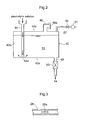
- FIG. 1 is a schematic explanation view of an electrolyzer apparatus 10 according to the present invention. As shown, there are provided separately a cylindrical anode tank 14 having a plate-like anode 12 formed of Pt/Ir plated titanium electrode (10 mm x 20 mm) and a cylindrical cathode tank 18 having a plate-like cathode 16 formed of a titanium electrode (10 mm x 20 mm).
- the anode tank 14 includes a feed opening 20 for feeding an amount of electrolytic solution 13 into the tank, an anode aeration device 22 for feeding aeration air(air or inactive gas) into the electrolytic solution 13 fed from the feed opening 20, and a gas extraction pipe 24 for establishing air communication between the inside and the outside of the anode tank 14 and guiding gas generated in the anode tank 14 to the outside.
- the cathode tank 18 too includes a cathode aeration device 26 for feeding aeration air (air or inactive gas) into the electrolytic solution 13.
- the anode tank 14 and the cathode tank 18 are connected to each other at the respective lower portions thereof via a communication pipe 28. More particularly, there is provided the communication pipe 28 having an inner diameter ranging from 2 mm to 20 mm (diameter) having one end thereof connected to the lower portion of the anode tank 14 and the other end thereof connected to the lower portion of the cathode tank 18.
- the communication pipe 28 having an inner diameter ranging from 2 mm to 20 mm (diameter) having one end thereof connected to the lower portion of the anode tank 14 and the other end thereof connected to the lower portion of the cathode tank 18.
- the electrolytic solution 13 fed to the anode tank 14 flows into the cathode tank 18 and also via the electrolytic solution 13 present inside this communication pipe 28, electric conduction is made possible between the anode 12 and the cathode 16.
- a constricted portion 28a which forms a reduced inner diameter (diameter: 0.5 mm to 5 mm) for a part thereof (in the range of 2 mm to 20 mm length).
- the anode tank 14 and the cathode tank 18 are connected to each other at the respective upper portions thereof via a gas collection pipe 30 for allowing air communication therebetween.
- the inside of the anode tank 14 will be charged through the feed opening 20 with an amount of electrolytic solution 13 containing 25 wt% of sodium chlorite and sodium chloride (in 1000 g of electrolytic solution, 25 wt% of sodium chlorite 66 ml (sodium chlorite 2 wt%), 100% sodium chloride 100 g (sodium chloride 10 wt%), water 834g).
- electrolytic solution 13 will flow through the communication pipe 28 to be charged in the cathode tank 18 as well.
- aeration air air or inactive gas
- chlorine dioxide generated inside the anode tank 14 by the electrolysis will be discharged together with the aeration air through the gas extraction pipe 24 to the outside of the anode tank 14.
- the electrolytic solution 13 may be supplemented intermittently and continuously into the anode tank 14 through the feed opening 20 with using an electrolytic solution instillation device 40 ( Fig. 2 ). Specifically, the electrolytic solution 13 will be instilled continuously every five (5) minutes by a rate of 1 to 10 mL/h. In this way, as the electrolytic solution 13 is continuously supplemented from the feed opening 20 of the anode tank 14 by the electrolytic solution instillation device, there occurs a slow flow of electrolytic solution 13 from the anode tank 14 toward the cathode tank 18, which flow effectively resists reverse flow of the electrolytic solution 13 of the cathode tank 18 to the anode tank 14. With this, it is possible to prevent deterioration of electrolytic solution when acid/base properties change on the cathode 16 side from adversely affects the anode side 14, so that the gas generation efficiency is maintained constant.
- the electrolytic solution 13 present inside the cathode tank 18 will flow down through the inside of the electrolytic solution collection pipe 32 into an exhaust solution tank 34 and then exhausted continuously from an exhaust pipe 38. And, the air pressure adjustment (pressure vent) in the course of this will be effected by a vent pipe 36.
- the constricted portion 28a forming a reduced diameter at a portion thereof.
- the reverse flow of the electrolytic solution 13 inside the cathode tank 18 into the anode tank 14 can be prevented even more effectively. If the prevention of the reverse flow of the electrolytic solution 13 inside the cathode tank 18 into the anode tank 14 alone is considered, it will suffice to employ a pipe-like member which is narrow along the entire length thereof as the communication pipe 28. In such case, however, the flow of the electric current too becomes difficult.
- a tank main body 42 of the agent solution tank 40 consists of a bottom plate 42a, a peripheral side plate 42b and a top plate 42c.
- the top plate 42c mounts an inlet pipe 44 (having a vent 44a at its lower end portion) extending through the plate 42c downwards to reach the bottom plate 42a and a depressurization pipe 46 (having an opening 46a that can be freely opened/closed).
- the bottom plate 42a mounts a feed/discharge pipe 48 connected to the feed opening 20 of the anode tank 14.
- This feed/discharge pipe 48 incorporates an electromagnetic valve 50 having a timer for adjusting the flow rate of the electrolytic solution 13 flowing therein.
- the opening 46a of the depressurization pipe 46 will be opened and the feed/discharge pipe 48 will be closed. Then, under this condition, the electrolytic solution 13 after its adjustment will be introduced into the tank main body 42 through the inlet pipe 44 until the electrolytic solution 13 is charged up to a predetermined level (see the virtual dot line in Fig. 2 ). Thereafter, the opening 46a of the depressurization pipe 46 will be closed and the feed/discharge pipe 48 will be opened, whereby the electrolytic solution 13 inside the tank main body 42 will flow down under the effect of gravity and will be fed into the anode tank 14 via the feed opening 20. In the course of this, since the opening 46a of the depressurization pipe 46 is closed, the inside pressure of the tank main body 42 will become a negative pressure in association with the downflow of the electrolytic solution 13.
- the electrolytic solution 13 inside the agent solution tank 40 will decrease correspondingly.
- the inside pressure of the tank main body 42 has become a negative pressure as described above and also the vent hole 44a is provided at the lower end of the inlet pipe 44 communicated with the atmosphere, the level of the electrolytic solution 13 stopped at the lower end position of the inlet pipe 44 will be maintained as it is.
- the electrolytic solution 13 tending to flow inside the feed/discharge pipe 48 is free from the pressure change that occurs due to the change in the electrolytic solution storage amount (self weight change) inside the tank main body 42.
- the flow rate of the electrolytic solution 13 flowing inside the feed/discharge pipe 48 can be extremely stable, so that even if this rate is very low, it can be maintained at a substantially fixed rate.
- gas generation amount per unit period being a relatively small (e.g. 0.01 mg to 100 mg/h) is contemplated, this can be coped with sufficiently and the gas can be generated continuously by a substantially fixed ratio for an extended period of time.
- the electrolyzer apparatus according to the present invention can be used for an electrolysis for generating a gas from the side of the anode which is effected with the anode and the cathode being kept submerged in an electrolytic solution.
Landscapes
- Chemical & Material Sciences (AREA)
- Engineering & Computer Science (AREA)
- Chemical Kinetics & Catalysis (AREA)
- Electrochemistry (AREA)
- Materials Engineering (AREA)
- Metallurgy (AREA)
- Organic Chemistry (AREA)
- Inorganic Chemistry (AREA)
- Automation & Control Theory (AREA)
- Electrolytic Production Of Non-Metals, Compounds, Apparatuses Therefor (AREA)
- Water Treatment By Electricity Or Magnetism (AREA)
Applications Claiming Priority (2)
| Application Number | Priority Date | Filing Date | Title |
|---|---|---|---|
| JP2010064554 | 2010-03-19 | ||
| PCT/JP2011/056418 WO2011115220A1 (fr) | 2010-03-19 | 2011-03-17 | Électrolyseur |
Publications (3)
| Publication Number | Publication Date |
|---|---|
| EP2548997A1 true EP2548997A1 (fr) | 2013-01-23 |
| EP2548997A4 EP2548997A4 (fr) | 2014-03-19 |
| EP2548997B1 EP2548997B1 (fr) | 2015-05-27 |
Family
ID=44649303
Family Applications (1)
| Application Number | Title | Priority Date | Filing Date |
|---|---|---|---|
| EP11756404.7A Not-in-force EP2548997B1 (fr) | 2010-03-19 | 2011-03-17 | Appareil d'électrolyse |
Country Status (9)
| Country | Link |
|---|---|
| US (1) | US9315911B2 (fr) |
| EP (1) | EP2548997B1 (fr) |
| JP (1) | JP5751543B2 (fr) |
| KR (1) | KR101710223B1 (fr) |
| CN (1) | CN102812160B (fr) |
| AU (1) | AU2011228059B2 (fr) |
| CA (1) | CA2793822A1 (fr) |
| TW (1) | TWI539031B (fr) |
| WO (1) | WO2011115220A1 (fr) |
Families Citing this family (8)
| Publication number | Priority date | Publication date | Assignee | Title |
|---|---|---|---|---|
| JP5893637B2 (ja) * | 2011-10-14 | 2016-03-23 | 浦安電設株式会社 | 水素−酸素ガス発生装置 |
| HK1226451A1 (en) * | 2013-09-09 | 2017-09-29 | Taiko Pharmaceutical Co., Ltd. | Chlorine dioxide production device and chlorine dioxide production method |
| KR101485018B1 (ko) * | 2014-05-07 | 2015-01-28 | (주) 시온텍 | 이산화염소 가스 발생 장치 및 그 발생 시스템 |
| WO2018043711A1 (fr) * | 2016-09-05 | 2018-03-08 | 株式会社大阪ソーダ | Dispositif de génération de dioxyde de chlore et procédé de génération de dioxyde de chlore |
| CN113740395B (zh) * | 2021-09-10 | 2022-10-04 | 厦门大学 | 一种用于电化学分析的电解池及其应用 |
| CN114934296B (zh) * | 2022-04-21 | 2024-07-05 | 湖北绿钨资源循环有限公司 | 一种曝气辅助电解废硬质合金回收碳化钨的方法 |
| JPWO2024135332A1 (fr) * | 2022-12-19 | 2024-06-27 | ||
| CN121161316B (zh) * | 2025-11-14 | 2026-01-30 | 华东理工大学 | 一种采用双路定向曝气的管式电解槽系统和方法 |
Family Cites Families (18)
| Publication number | Priority date | Publication date | Assignee | Title |
|---|---|---|---|---|
| US2163793A (en) | 1937-06-08 | 1939-06-27 | Mathieson Alkall Works Inc | Production of chlorine dioxide |
| DE692763C (de) * | 1937-11-19 | 1942-01-15 | Paul Wever Kom Ges | rbinder aus Blech oder Draht |
| GB692763A (en) * | 1951-02-20 | 1953-06-10 | Bayer Ag | Production of chlorine dioxide |
| US3681228A (en) * | 1969-02-06 | 1972-08-01 | Walter D Komhyr | Electrochemical concentration cell for gas analysis |
| CN2061177U (zh) * | 1989-10-18 | 1990-08-29 | 中国人民解放军沈阳军区后勤部基建营房部 | 电解二氧化氯发生器 |
| JP3181795B2 (ja) * | 1994-10-28 | 2001-07-03 | オルガノ株式会社 | 電解水製造装置 |
| JP3052124B2 (ja) * | 1995-12-22 | 2000-06-12 | 株式会社ハクキン | 水素ガス製造機構 |
| US5965004A (en) * | 1996-03-13 | 1999-10-12 | Sterling Pulp Chemicals, Ltd. | Chlorine dioxide generation for water treatment |
| JP3849725B2 (ja) | 1996-04-11 | 2006-11-22 | 水道機工株式会社 | 二酸化塩素の製造方法 |
| CN1188740A (zh) * | 1996-12-23 | 1998-07-29 | 埃勒夫阿托化学有限公司 | 二氧化氯的制备方法 |
| CN2335951Y (zh) * | 1998-07-29 | 1999-09-01 | 温镜新 | 二氧化氯消毒剂发生器 |
| JP2000212787A (ja) * | 1999-01-26 | 2000-08-02 | Chemicoat & Co Ltd | 電解方法 |
| CN2359297Y (zh) * | 1999-02-23 | 2000-01-19 | 王培林 | 电解法高效二氧化氯发生器 |
| JP3949088B2 (ja) * | 2003-08-04 | 2007-07-25 | 大幸薬品株式会社 | 二酸化塩素製造装置 |
| JP2006346650A (ja) | 2005-06-20 | 2006-12-28 | Sawada Kinji | アルカリ殺菌水製造装置、アルカリ殺菌水製造方法 |
| JP2009154143A (ja) | 2007-12-26 | 2009-07-16 | Fujiwara Sangyo Kk | 掻寄装置 |
| CN103422115B (zh) * | 2008-06-19 | 2016-09-07 | 大幸药品株式会社 | 1液型电解式的二氧化氯的制造方法 |
| CN101591786B (zh) * | 2009-06-22 | 2011-03-16 | 陈维军 | 电解法二氧化氯发生器及电解槽 |
-
2011
- 2011-03-17 EP EP11756404.7A patent/EP2548997B1/fr not_active Not-in-force
- 2011-03-17 US US13/634,145 patent/US9315911B2/en not_active Expired - Fee Related
- 2011-03-17 KR KR1020127026903A patent/KR101710223B1/ko not_active Expired - Fee Related
- 2011-03-17 CN CN201180014319.4A patent/CN102812160B/zh not_active Expired - Fee Related
- 2011-03-17 CA CA2793822A patent/CA2793822A1/fr not_active Abandoned
- 2011-03-17 AU AU2011228059A patent/AU2011228059B2/en not_active Ceased
- 2011-03-17 JP JP2012505748A patent/JP5751543B2/ja active Active
- 2011-03-17 WO PCT/JP2011/056418 patent/WO2011115220A1/fr not_active Ceased
- 2011-03-18 TW TW100109353A patent/TWI539031B/zh not_active IP Right Cessation
Also Published As
| Publication number | Publication date |
|---|---|
| AU2011228059B2 (en) | 2015-04-02 |
| TW201207156A (en) | 2012-02-16 |
| CA2793822A1 (fr) | 2011-09-22 |
| JPWO2011115220A1 (ja) | 2013-07-04 |
| TWI539031B (zh) | 2016-06-21 |
| EP2548997A4 (fr) | 2014-03-19 |
| CN102812160A (zh) | 2012-12-05 |
| EP2548997B1 (fr) | 2015-05-27 |
| KR20130037678A (ko) | 2013-04-16 |
| KR101710223B1 (ko) | 2017-02-24 |
| US9315911B2 (en) | 2016-04-19 |
| AU2011228059A1 (en) | 2012-09-27 |
| WO2011115220A1 (fr) | 2011-09-22 |
| CN102812160B (zh) | 2015-06-03 |
| JP5751543B2 (ja) | 2015-07-22 |
| US20130043126A1 (en) | 2013-02-21 |
| HK1179666A1 (zh) | 2013-10-04 |
Similar Documents
| Publication | Publication Date | Title |
|---|---|---|
| EP2548997B1 (fr) | Appareil d'électrolyse | |
| US11414767B2 (en) | Electrolytic chlorine dioxide gas manufacturing device | |
| TW201006962A (en) | Method of manufacturing chlorine dioxide by mono liquid type electrolyte formula | |
| CN102383143B (zh) | 用于电解锗烷工艺的电极 | |
| HK1179667A (en) | Electrolyzer | |
| US4919791A (en) | Controlled operation of high current density oxygen consuming cathode cells to prevent hydrogen formation | |
| JP6891894B2 (ja) | 二酸化塩素発生装置及び二酸化塩素発生方法 | |
| JP4051774B2 (ja) | 電解装置 | |
| CN111422955B (zh) | 制取次氯酸水装置及方法 | |
| JP2017110277A (ja) | 二酸化塩素の製造方法 | |
| HK1179666B (en) | Electrolyzer | |
| JP2000064076A (ja) | 次亜塩素酸ナトリウム溶液生成装置 | |
| JP2002146576A (ja) | 無隔膜式電気分解方法及び装置 | |
| HK1234454B (en) | Device for electrolytically producing chlorine dioxide gas | |
| HK1234454A1 (en) | Device for electrolytically producing chlorine dioxide gas | |
| HK1191068B (en) | Method for producing chlorine dioxide with single-liquid electrolysis | |
| HK1191068A (en) | Method for producing chlorine dioxide with single-liquid electrolysis |
Legal Events
| Date | Code | Title | Description |
|---|---|---|---|
| PUAI | Public reference made under article 153(3) epc to a published international application that has entered the european phase |
Free format text: ORIGINAL CODE: 0009012 |
|
| 17P | Request for examination filed |
Effective date: 20121010 |
|
| AK | Designated contracting states |
Kind code of ref document: A1 Designated state(s): AL AT BE BG CH CY CZ DE DK EE ES FI FR GB GR HR HU IE IS IT LI LT LU LV MC MK MT NL NO PL PT RO RS SE SI SK SM TR |
|
| DAX | Request for extension of the european patent (deleted) | ||
| REG | Reference to a national code |
Ref country code: HK Ref legal event code: DE Ref document number: 1179667 Country of ref document: HK |
|
| RIC1 | Information provided on ipc code assigned before grant |
Ipc: C25B 1/26 20060101ALI20140205BHEP Ipc: C25B 9/00 20060101AFI20140205BHEP |
|
| A4 | Supplementary search report drawn up and despatched |
Effective date: 20140214 |
|
| GRAP | Despatch of communication of intention to grant a patent |
Free format text: ORIGINAL CODE: EPIDOSNIGR1 |
|
| INTG | Intention to grant announced |
Effective date: 20150129 |
|
| GRAS | Grant fee paid |
Free format text: ORIGINAL CODE: EPIDOSNIGR3 |
|
| GRAA | (expected) grant |
Free format text: ORIGINAL CODE: 0009210 |
|
| AK | Designated contracting states |
Kind code of ref document: B1 Designated state(s): AL AT BE BG CH CY CZ DE DK EE ES FI FR GB GR HR HU IE IS IT LI LT LU LV MC MK MT NL NO PL PT RO RS SE SI SK SM TR |
|
| REG | Reference to a national code |
Ref country code: GB Ref legal event code: FG4D |
|
| REG | Reference to a national code |
Ref country code: CH Ref legal event code: EP |
|
| REG | Reference to a national code |
Ref country code: AT Ref legal event code: REF Ref document number: 728925 Country of ref document: AT Kind code of ref document: T Effective date: 20150615 |
|
| REG | Reference to a national code |
Ref country code: IE Ref legal event code: FG4D |
|
| REG | Reference to a national code |
Ref country code: CH Ref legal event code: NV Representative=s name: AMMANN PATENTANWAELTE AG BERN, CH |
|
| REG | Reference to a national code |
Ref country code: DE Ref legal event code: R096 Ref document number: 602011016790 Country of ref document: DE |
|
| REG | Reference to a national code |
Ref country code: AT Ref legal event code: MK05 Ref document number: 728925 Country of ref document: AT Kind code of ref document: T Effective date: 20150527 |
|
| REG | Reference to a national code |
Ref country code: LT Ref legal event code: MG4D |
|
| PG25 | Lapsed in a contracting state [announced via postgrant information from national office to epo] |
Ref country code: ES Free format text: LAPSE BECAUSE OF FAILURE TO SUBMIT A TRANSLATION OF THE DESCRIPTION OR TO PAY THE FEE WITHIN THE PRESCRIBED TIME-LIMIT Effective date: 20150527 Ref country code: PT Free format text: LAPSE BECAUSE OF FAILURE TO SUBMIT A TRANSLATION OF THE DESCRIPTION OR TO PAY THE FEE WITHIN THE PRESCRIBED TIME-LIMIT Effective date: 20150928 Ref country code: HR Free format text: LAPSE BECAUSE OF FAILURE TO SUBMIT A TRANSLATION OF THE DESCRIPTION OR TO PAY THE FEE WITHIN THE PRESCRIBED TIME-LIMIT Effective date: 20150527 Ref country code: LT Free format text: LAPSE BECAUSE OF FAILURE TO SUBMIT A TRANSLATION OF THE DESCRIPTION OR TO PAY THE FEE WITHIN THE PRESCRIBED TIME-LIMIT Effective date: 20150527 Ref country code: NO Free format text: LAPSE BECAUSE OF FAILURE TO SUBMIT A TRANSLATION OF THE DESCRIPTION OR TO PAY THE FEE WITHIN THE PRESCRIBED TIME-LIMIT Effective date: 20150827 Ref country code: FI Free format text: LAPSE BECAUSE OF FAILURE TO SUBMIT A TRANSLATION OF THE DESCRIPTION OR TO PAY THE FEE WITHIN THE PRESCRIBED TIME-LIMIT Effective date: 20150527 |
|
| REG | Reference to a national code |
Ref country code: NL Ref legal event code: MP Effective date: 20150527 |
|
| PG25 | Lapsed in a contracting state [announced via postgrant information from national office to epo] |
Ref country code: RS Free format text: LAPSE BECAUSE OF FAILURE TO SUBMIT A TRANSLATION OF THE DESCRIPTION OR TO PAY THE FEE WITHIN THE PRESCRIBED TIME-LIMIT Effective date: 20150527 Ref country code: LV Free format text: LAPSE BECAUSE OF FAILURE TO SUBMIT A TRANSLATION OF THE DESCRIPTION OR TO PAY THE FEE WITHIN THE PRESCRIBED TIME-LIMIT Effective date: 20150527 Ref country code: AT Free format text: LAPSE BECAUSE OF FAILURE TO SUBMIT A TRANSLATION OF THE DESCRIPTION OR TO PAY THE FEE WITHIN THE PRESCRIBED TIME-LIMIT Effective date: 20150527 Ref country code: IS Free format text: LAPSE BECAUSE OF FAILURE TO SUBMIT A TRANSLATION OF THE DESCRIPTION OR TO PAY THE FEE WITHIN THE PRESCRIBED TIME-LIMIT Effective date: 20150927 Ref country code: BG Free format text: LAPSE BECAUSE OF FAILURE TO SUBMIT A TRANSLATION OF THE DESCRIPTION OR TO PAY THE FEE WITHIN THE PRESCRIBED TIME-LIMIT Effective date: 20150827 Ref country code: GR Free format text: LAPSE BECAUSE OF FAILURE TO SUBMIT A TRANSLATION OF THE DESCRIPTION OR TO PAY THE FEE WITHIN THE PRESCRIBED TIME-LIMIT Effective date: 20150828 |
|
| PG25 | Lapsed in a contracting state [announced via postgrant information from national office to epo] |
Ref country code: EE Free format text: LAPSE BECAUSE OF FAILURE TO SUBMIT A TRANSLATION OF THE DESCRIPTION OR TO PAY THE FEE WITHIN THE PRESCRIBED TIME-LIMIT Effective date: 20150527 Ref country code: DK Free format text: LAPSE BECAUSE OF FAILURE TO SUBMIT A TRANSLATION OF THE DESCRIPTION OR TO PAY THE FEE WITHIN THE PRESCRIBED TIME-LIMIT Effective date: 20150527 |
|
| PG25 | Lapsed in a contracting state [announced via postgrant information from national office to epo] |
Ref country code: RO Free format text: LAPSE BECAUSE OF NON-PAYMENT OF DUE FEES Effective date: 20150527 Ref country code: CZ Free format text: LAPSE BECAUSE OF FAILURE TO SUBMIT A TRANSLATION OF THE DESCRIPTION OR TO PAY THE FEE WITHIN THE PRESCRIBED TIME-LIMIT Effective date: 20150527 Ref country code: SK Free format text: LAPSE BECAUSE OF FAILURE TO SUBMIT A TRANSLATION OF THE DESCRIPTION OR TO PAY THE FEE WITHIN THE PRESCRIBED TIME-LIMIT Effective date: 20150527 Ref country code: PL Free format text: LAPSE BECAUSE OF FAILURE TO SUBMIT A TRANSLATION OF THE DESCRIPTION OR TO PAY THE FEE WITHIN THE PRESCRIBED TIME-LIMIT Effective date: 20150527 |
|
| REG | Reference to a national code |
Ref country code: DE Ref legal event code: R097 Ref document number: 602011016790 Country of ref document: DE |
|
| REG | Reference to a national code |
Ref country code: FR Ref legal event code: PLFP Year of fee payment: 6 |
|
| PLBE | No opposition filed within time limit |
Free format text: ORIGINAL CODE: 0009261 |
|
| STAA | Information on the status of an ep patent application or granted ep patent |
Free format text: STATUS: NO OPPOSITION FILED WITHIN TIME LIMIT |
|
| PG25 | Lapsed in a contracting state [announced via postgrant information from national office to epo] |
Ref country code: IT Free format text: LAPSE BECAUSE OF FAILURE TO SUBMIT A TRANSLATION OF THE DESCRIPTION OR TO PAY THE FEE WITHIN THE PRESCRIBED TIME-LIMIT Effective date: 20150527 |
|
| 26N | No opposition filed |
Effective date: 20160301 |
|
| PG25 | Lapsed in a contracting state [announced via postgrant information from national office to epo] |
Ref country code: SI Free format text: LAPSE BECAUSE OF FAILURE TO SUBMIT A TRANSLATION OF THE DESCRIPTION OR TO PAY THE FEE WITHIN THE PRESCRIBED TIME-LIMIT Effective date: 20150527 |
|
| PG25 | Lapsed in a contracting state [announced via postgrant information from national office to epo] |
Ref country code: BE Free format text: LAPSE BECAUSE OF FAILURE TO SUBMIT A TRANSLATION OF THE DESCRIPTION OR TO PAY THE FEE WITHIN THE PRESCRIBED TIME-LIMIT Effective date: 20150527 |
|
| PG25 | Lapsed in a contracting state [announced via postgrant information from national office to epo] |
Ref country code: MC Free format text: LAPSE BECAUSE OF FAILURE TO SUBMIT A TRANSLATION OF THE DESCRIPTION OR TO PAY THE FEE WITHIN THE PRESCRIBED TIME-LIMIT Effective date: 20150527 Ref country code: LU Free format text: LAPSE BECAUSE OF FAILURE TO SUBMIT A TRANSLATION OF THE DESCRIPTION OR TO PAY THE FEE WITHIN THE PRESCRIBED TIME-LIMIT Effective date: 20160317 |
|
| REG | Reference to a national code |
Ref country code: IE Ref legal event code: MM4A |
|
| PG25 | Lapsed in a contracting state [announced via postgrant information from national office to epo] |
Ref country code: IE Free format text: LAPSE BECAUSE OF NON-PAYMENT OF DUE FEES Effective date: 20160317 |
|
| REG | Reference to a national code |
Ref country code: FR Ref legal event code: PLFP Year of fee payment: 7 |
|
| PG25 | Lapsed in a contracting state [announced via postgrant information from national office to epo] |
Ref country code: NL Free format text: LAPSE BECAUSE OF FAILURE TO SUBMIT A TRANSLATION OF THE DESCRIPTION OR TO PAY THE FEE WITHIN THE PRESCRIBED TIME-LIMIT Effective date: 20150527 Ref country code: SE Free format text: LAPSE BECAUSE OF FAILURE TO SUBMIT A TRANSLATION OF THE DESCRIPTION OR TO PAY THE FEE WITHIN THE PRESCRIBED TIME-LIMIT Effective date: 20150527 |
|
| PG25 | Lapsed in a contracting state [announced via postgrant information from national office to epo] |
Ref country code: MT Free format text: LAPSE BECAUSE OF FAILURE TO SUBMIT A TRANSLATION OF THE DESCRIPTION OR TO PAY THE FEE WITHIN THE PRESCRIBED TIME-LIMIT Effective date: 20150527 |
|
| REG | Reference to a national code |
Ref country code: FR Ref legal event code: PLFP Year of fee payment: 8 |
|
| PGFP | Annual fee paid to national office [announced via postgrant information from national office to epo] |
Ref country code: CH Payment date: 20180326 Year of fee payment: 8 Ref country code: DE Payment date: 20180322 Year of fee payment: 8 Ref country code: GB Payment date: 20180326 Year of fee payment: 8 |
|
| PG25 | Lapsed in a contracting state [announced via postgrant information from national office to epo] |
Ref country code: HU Free format text: LAPSE BECAUSE OF FAILURE TO SUBMIT A TRANSLATION OF THE DESCRIPTION OR TO PAY THE FEE WITHIN THE PRESCRIBED TIME-LIMIT; INVALID AB INITIO Effective date: 20110317 Ref country code: SM Free format text: LAPSE BECAUSE OF FAILURE TO SUBMIT A TRANSLATION OF THE DESCRIPTION OR TO PAY THE FEE WITHIN THE PRESCRIBED TIME-LIMIT Effective date: 20150527 Ref country code: CY Free format text: LAPSE BECAUSE OF FAILURE TO SUBMIT A TRANSLATION OF THE DESCRIPTION OR TO PAY THE FEE WITHIN THE PRESCRIBED TIME-LIMIT Effective date: 20150527 |
|
| PGFP | Annual fee paid to national office [announced via postgrant information from national office to epo] |
Ref country code: FR Payment date: 20180326 Year of fee payment: 8 |
|
| PG25 | Lapsed in a contracting state [announced via postgrant information from national office to epo] |
Ref country code: MT Free format text: LAPSE BECAUSE OF FAILURE TO SUBMIT A TRANSLATION OF THE DESCRIPTION OR TO PAY THE FEE WITHIN THE PRESCRIBED TIME-LIMIT Effective date: 20160331 Ref country code: TR Free format text: LAPSE BECAUSE OF FAILURE TO SUBMIT A TRANSLATION OF THE DESCRIPTION OR TO PAY THE FEE WITHIN THE PRESCRIBED TIME-LIMIT Effective date: 20150527 Ref country code: MK Free format text: LAPSE BECAUSE OF FAILURE TO SUBMIT A TRANSLATION OF THE DESCRIPTION OR TO PAY THE FEE WITHIN THE PRESCRIBED TIME-LIMIT Effective date: 20150527 |
|
| PG25 | Lapsed in a contracting state [announced via postgrant information from national office to epo] |
Ref country code: AL Free format text: LAPSE BECAUSE OF FAILURE TO SUBMIT A TRANSLATION OF THE DESCRIPTION OR TO PAY THE FEE WITHIN THE PRESCRIBED TIME-LIMIT Effective date: 20150527 |
|
| REG | Reference to a national code |
Ref country code: DE Ref legal event code: R119 Ref document number: 602011016790 Country of ref document: DE |
|
| REG | Reference to a national code |
Ref country code: HK Ref legal event code: WD Ref document number: 1179667 Country of ref document: HK |
|
| REG | Reference to a national code |
Ref country code: CH Ref legal event code: PL |
|
| GBPC | Gb: european patent ceased through non-payment of renewal fee |
Effective date: 20190317 |
|
| PG25 | Lapsed in a contracting state [announced via postgrant information from national office to epo] |
Ref country code: LI Free format text: LAPSE BECAUSE OF NON-PAYMENT OF DUE FEES Effective date: 20190331 Ref country code: GB Free format text: LAPSE BECAUSE OF NON-PAYMENT OF DUE FEES Effective date: 20190317 Ref country code: DE Free format text: LAPSE BECAUSE OF NON-PAYMENT OF DUE FEES Effective date: 20191001 Ref country code: CH Free format text: LAPSE BECAUSE OF NON-PAYMENT OF DUE FEES Effective date: 20190331 |
|
| PG25 | Lapsed in a contracting state [announced via postgrant information from national office to epo] |
Ref country code: FR Free format text: LAPSE BECAUSE OF NON-PAYMENT OF DUE FEES Effective date: 20190331 |