EP2549174A2 - Eclairage - Google Patents
Eclairage Download PDFInfo
- Publication number
- EP2549174A2 EP2549174A2 EP12177291A EP12177291A EP2549174A2 EP 2549174 A2 EP2549174 A2 EP 2549174A2 EP 12177291 A EP12177291 A EP 12177291A EP 12177291 A EP12177291 A EP 12177291A EP 2549174 A2 EP2549174 A2 EP 2549174A2
- Authority
- EP
- European Patent Office
- Prior art keywords
- housing
- fastening device
- luminaire according
- fastening
- wall
- Prior art date
- Legal status (The legal status is an assumption and is not a legal conclusion. Google has not performed a legal analysis and makes no representation as to the accuracy of the status listed.)
- Withdrawn
Links
- 230000002093 peripheral effect Effects 0.000 claims description 7
- 230000003287 optical effect Effects 0.000 claims description 4
- 229920003023 plastic Polymers 0.000 abstract description 11
- 238000000926 separation method Methods 0.000 abstract description 2
- 238000006073 displacement reaction Methods 0.000 description 4
- 238000005452 bending Methods 0.000 description 2
- 239000000725 suspension Substances 0.000 description 2
- 230000004308 accommodation Effects 0.000 description 1
- 238000007796 conventional method Methods 0.000 description 1
- 230000001419 dependent effect Effects 0.000 description 1
- 238000013461 design Methods 0.000 description 1
- 238000011161 development Methods 0.000 description 1
- 230000018109 developmental process Effects 0.000 description 1
- 238000005516 engineering process Methods 0.000 description 1
- 210000004907 gland Anatomy 0.000 description 1
- 238000003780 insertion Methods 0.000 description 1
- 230000037431 insertion Effects 0.000 description 1
- 238000009423 ventilation Methods 0.000 description 1
Images

Classifications
-
- F—MECHANICAL ENGINEERING; LIGHTING; HEATING; WEAPONS; BLASTING
- F21—LIGHTING
- F21S—NON-PORTABLE LIGHTING DEVICES; SYSTEMS THEREOF; VEHICLE LIGHTING DEVICES SPECIALLY ADAPTED FOR VEHICLE EXTERIORS
- F21S8/00—Lighting devices intended for fixed installation
- F21S8/04—Lighting devices intended for fixed installation intended only for mounting on a ceiling or the like overhead structures
- F21S8/043—Lighting devices intended for fixed installation intended only for mounting on a ceiling or the like overhead structures mounted by means of a rigid support, e.g. bracket or arm
-
- F—MECHANICAL ENGINEERING; LIGHTING; HEATING; WEAPONS; BLASTING
- F21—LIGHTING
- F21V—FUNCTIONAL FEATURES OR DETAILS OF LIGHTING DEVICES OR SYSTEMS THEREOF; STRUCTURAL COMBINATIONS OF LIGHTING DEVICES WITH OTHER ARTICLES, NOT OTHERWISE PROVIDED FOR
- F21V17/00—Fastening of component parts of lighting devices, e.g. shades, globes, refractors, reflectors, filters, screens, grids or protective cages
- F21V17/10—Fastening of component parts of lighting devices, e.g. shades, globes, refractors, reflectors, filters, screens, grids or protective cages characterised by specific fastening means or way of fastening
- F21V17/12—Fastening of component parts of lighting devices, e.g. shades, globes, refractors, reflectors, filters, screens, grids or protective cages characterised by specific fastening means or way of fastening by screwing
-
- F—MECHANICAL ENGINEERING; LIGHTING; HEATING; WEAPONS; BLASTING
- F21—LIGHTING
- F21Y—INDEXING SCHEME ASSOCIATED WITH SUBCLASSES F21K, F21L, F21S and F21V, RELATING TO THE FORM OR THE KIND OF THE LIGHT SOURCES OR OF THE COLOUR OF THE LIGHT EMITTED
- F21Y2105/00—Planar light sources
-
- F—MECHANICAL ENGINEERING; LIGHTING; HEATING; WEAPONS; BLASTING
- F21—LIGHTING
- F21Y—INDEXING SCHEME ASSOCIATED WITH SUBCLASSES F21K, F21L, F21S and F21V, RELATING TO THE FORM OR THE KIND OF THE LIGHT SOURCES OR OF THE COLOUR OF THE LIGHT EMITTED
- F21Y2115/00—Light-generating elements of semiconductor light sources
- F21Y2115/10—Light-emitting diodes [LED]
-
- G—PHYSICS
- G02—OPTICS
- G02B—OPTICAL ELEMENTS, SYSTEMS OR APPARATUS
- G02B6/00—Light guides; Structural details of arrangements comprising light guides and other optical elements, e.g. couplings
- G02B6/0001—Light guides; Structural details of arrangements comprising light guides and other optical elements, e.g. couplings specially adapted for lighting devices or systems
- G02B6/0011—Light guides; Structural details of arrangements comprising light guides and other optical elements, e.g. couplings specially adapted for lighting devices or systems the light guides being planar or of plate-like form
- G02B6/0081—Mechanical or electrical aspects of the light guide and light source in the lighting device peculiar to the adaptation to planar light guides, e.g. concerning packaging
- G02B6/0086—Positioning aspects
Definitions
- the invention relates to a lamp with a housing for receiving the lamp and with a fastening device by means of which the housing can be fastened to a supporting part.
- LED lighting is being used more and more frequently in modern lighting technology. These have a housing in which the bulbs are arranged.
- a transparent plastic is often provided, which is arranged on one side adjacent to a reflector. The LEDs light up from one side into the plastic. The light then exits via a diffuser which is arranged on the side of the transparent plastic facing away from the reflector. In this way, even surface lights can be realized.
- a power supply is required. This power supply can often be hidden in so-called grid ceilings.
- the size of the LED panel, so the housing for receiving the light source and the optical elements for light distribution is then sized so that an element of such a grid ceiling can be replaced by the lamp.
- the LED panel can be hung on a ceiling, for example via a cable system.
- the problem here is the accommodation of the control electronics or the power supply.
- the suspension ensures that a rigid connection to the load-bearing part of the building does not take place.
- such a cable suspension may be undesirable.
- the invention is therefore an object of the invention to provide a lamp in which an improved attachment to a supporting part of the building is possible.
- the object is achieved by the luminaire according to the invention with the feature of claim 1.
- the luminaire according to the invention has a housing for accommodating the luminous means and at least one optical element. Furthermore, the lamp includes a Fastening device, which is detachably connected to the housing and by means of which the housing can be mounted on a part carrying the luminaire. On the housing or on the fastening device, at least one fastening element is provided, which is insertable into a corresponding recess in the other of the fastening device or the housing. Introduced into this recess, the fastener is displaceable, wherein in the shifted state, a separation of the housing is prevented by the fastening device by applying a tensile force. In this way, for example, create a space in the mounting device, which receives the control electronics.
- This fastening device can be fixed to the supporting building part by conventional techniques, for example screws.
- the assembly of the housing with the light-emitting components arranged therein can then take place without the need for a further screw connection with the aid of the fastening elements and corresponding recesses.
- the fastener may be T-shaped in cross-section and engage in a recess which has substantially keyhole geometry.
- the head In the widened part of the keyhole, the head can be used to then be moved by sliding into the narrower part of the keyhole shaped cutout. In this state, the head can not be pulled out again through the narrower part, resulting in a fixation of the housing to the fastening device.
- the dependent claims relate to advantageous developments of the lamp according to the invention.
- a securing device to the housing.
- this securing device which can be connected at its end remote from the housing with the fastening device, unintentional displacement of the housing relative to the fastening device can be prevented. This ensures that the fasteners always remain in the narrow part of the recess and unintentional release of the housing is prevented.
- the housing has a frame and a flush-mounted in the frame rear wall.
- This rear wall is particularly preferably designed so that it performs supporting function, that is rigid. In this way, even large-scale elements can be realized, which are connected only via the fastening elements with the fastening device.
- the rigidity of the rear wall is used to prevent unwanted bending of the housing together with the internals arranged therein.
- the fastening elements are then preferably arranged on this rear wall.
- the rear wall has a groove on its side remote from the fastening device side. In this groove then electrical lines can be accommodated. This is particularly advantageous since an invisible supply of the electrical leads to the light sources is made possible. It can be arranged elsewhere in the power supply or the control unit for controlling the LEDs. It is particularly advantageous to design the fastening device so that the control unit or the power supply can be accommodated in the fastening device.
- the fastening device has a circumferential wall which creates a gap between the housing and the supporting part of the building.
- a flange for fixing to the supporting part and / or a housing-side flange is then preferably formed on this wall. In the housing-side flange, the recess corresponding to the fastening elements is preferably arranged.
- the flanges are preferably designed so that they do not fill the defined by the circumferential wall cross-section of the fastening device. In this way it can be ensured even with a fixation of the fastening device, for example on the ceiling or a wall, that the accessibility of the building-side power supply is easily possible.
- the housing-side flange is also designed so that a simple implementation of the electrical lines to the groove in the rear wall is easily possible. For this purpose, a passage opening is likewise provided corresponding to the position of the open region of the flange in the rear wall.
- the housing preferably has at least two LEDs, which illuminate on side surfaces in a transparent plastic. It is on the of the Fastening device facing away from this transparent plastic, preferably a diffuser arranged, which closes the housing in the direction of the room.
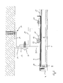
- FIG. 1 is a cross section through the luminaire according to the invention, which is attached for example to a ceiling is shown.
- the luminaire 1 consists essentially of two elements, namely the fastening device 2 and a housing 3 to be connected thereto.
- the housing 3 comprises a frame 4, which may extend, for example, rectangular.
- the frame 4 has circumferentially on a step into which a rear wall 5 is inserted. The height of the step is dimensioned so that the rear wall 5 is flush with the outer peripheral edge of the frame 4.
- a circumferential groove is also preferably provided in the region of the step, so that in a simple manner the rear wall 5 can be fastened by screwing into the groove on the frame 4.
- the thickness of the rear wall 5 is preferably dimensioned so that a certain flexural rigidity is achieved, so that bending of the entire housing 3 is reliably avoided.
- a transparent plastic 6 extends parallel to the rear wall 5.
- a diffuser 7 is arranged on the transparent plastic 6 in order to achieve a uniform light output of the entire luminaire.
- a reflector is arranged to deliver the introduced by at least two LED elements 8 at a side edge of the transparent plastic 6 light through the diffuser 7 to the room.
- Such housing with arranged therein optical Elements and lamps are known per se. These so-called LED panels are then, as it was explained in the introduction, arranged in space.
- the rear wall 5 has, on its side oriented toward the transparent plastic 6 side, a groove 10, in which electrical lines 9 are arranged. These electrical leads 9 supply the LEDs with power.
- the electrical leads 9 are led out of the housing 3 via an opening 11 in order to be able to connect them to an electrical control unit 12 via a plug connection 25.
- the electric control unit 12 is arranged in the fastening device 2.
- the fastening device 2 has a peripheral wall 13, which surrounds a space between a supporting part 16, to which the lamp 1 is to be fastened, and at the z. B. the control unit is fixed.
- ventilation slots 24 or holes may be arranged in the peripheral wall.
- a flange 14 is provided for fixing the fastening device 2 to the supporting part 16.
- the flange 14 may be formed circumferentially, wherein not all covered by the circumferential wall 13 cross-section is covered. Preferably, an opening remains, so that a slight introduction of the building-side power connection is. In the region of the flange 14 glands for fixing the lamp 1 are arranged on the building side.
- a housing-side flange 15 is formed on the peripheral wall 13. Also, this housing-side flange 15 leaves a part of the cross-section open to allow the introduction of the electrical leads 9.
- a securing element 19 is provided which prevents unintentional displacement of the housing 3.
- This securing element 19 is fixed to the rear wall 5 by means of a fixing element, for example a screw 20.
- a fixing element for example a screw 20.
- it is in Substantially Z-shaped designed and dimensioned so that it comes to rest with correctly mounted housing 3 with its remote from the rear wall 5 end of the circumferential wall 13. There it can be fixed by means of another screw 21.
- Such a fixation of the securing element 19 on the one hand on the rear wall 5 and on the other hand on the peripheral wall 13 prevents unintentional displacement of the housing 3 relative to the fastening device. 2
- the Fig. 2 shows an enlarged view in the section I of Fig. 1 , It can be seen that a fastening element 22 of the attachment 18 is fixed to the rear wall 5 of the housing 3. This can be done for example by screwing into a threaded hole in the rear wall 5.
- the fastening element 22 is formed in cross-section substantially T-shaped and thus comprises a stem and a relative to this enlarged in radius head.
- a recess is introduced in the housing-side flange 15 of the fastening device 2.
- This recess has an extended area and a narrower area, which are interconnected. While the extended area is dimensioned in its radial extent so that the head of the fastening element 15 can be passed, the region narrower compared to the dimensioned so that only the stem of the fastener 22 can be moved into it. In this way, in the narrower region of the recess 23, the head of the fastening element 22 comes into abutment with the surface of the housing-side flange 15 facing away from the housing 3. Pulling the fastening element 22 out of the recess 23 into the narrower region is thus impossible.
- Such fasteners may be distributed over the circumference along the housing-side flange 15.
- the number and positioning of the fasteners 18, 19 depends on the geometry of the lamp.
- the lamp according to the invention has the advantage that a simple attachment of the housing 3 to the fastening device 2 is possible without a screw is required. Only for securing a single screw is advantageous with which the securing element can be attached to the fastening device 2.
- the actual fixation of the housing 3 at the Fastening device 2, however, is invisible.
- the control electronics for driving the LED elements can be arranged in a formed within the fastening device 2 volume. Thus, it is not only hidden visually advantageous, but also protected by the peripheral wall 13 at the same time.
- the attachment of the fastening device 2 to the supporting part can be done in a conventional manner to the flange 14 by means of screw 17.
Landscapes
- Engineering & Computer Science (AREA)
- General Engineering & Computer Science (AREA)
- Non-Portable Lighting Devices Or Systems Thereof (AREA)
- Fastening Of Light Sources Or Lamp Holders (AREA)
- Securing Globes, Refractors, Reflectors Or The Like (AREA)
Applications Claiming Priority (1)
| Application Number | Priority Date | Filing Date | Title |
|---|---|---|---|
| DE102011079611A DE102011079611A1 (de) | 2011-07-22 | 2011-07-22 | Leuchte |
Publications (2)
| Publication Number | Publication Date |
|---|---|
| EP2549174A2 true EP2549174A2 (fr) | 2013-01-23 |
| EP2549174A3 EP2549174A3 (fr) | 2013-12-18 |
Family
ID=47018018
Family Applications (1)
| Application Number | Title | Priority Date | Filing Date |
|---|---|---|---|
| EP12177291.7A Withdrawn EP2549174A3 (fr) | 2011-07-22 | 2012-07-20 | Eclairage |
Country Status (2)
| Country | Link |
|---|---|
| EP (1) | EP2549174A3 (fr) |
| DE (1) | DE102011079611A1 (fr) |
Cited By (1)
| Publication number | Priority date | Publication date | Assignee | Title |
|---|---|---|---|---|
| EP3396243A1 (fr) * | 2017-04-25 | 2018-10-31 | Müller-Licht International GmbH | Luminaire pour un local humide |
Family Cites Families (5)
| Publication number | Priority date | Publication date | Assignee | Title |
|---|---|---|---|---|
| DE3244516C2 (de) * | 1982-12-02 | 1985-10-10 | Fränkische Leuchten GmbH, 8729 Königsberg | Vorrichtung zur lösbaren Verbindung des Geräteträgers mit der Schiene einer Leuchte für Leuchtstofflampen |
| DE19734601C2 (de) * | 1997-08-09 | 1999-10-07 | Reiss Int Gmbh | Befestigungsvorrichtung |
| DE29822575U1 (de) * | 1998-12-18 | 2000-04-20 | hülsta-werke Hüls GmbH & Co. KG, 48703 Stadtlohn | Vorrichtung zur Befestigung einer elektrischen Armatur an einem plattenförmigen Bauteil |
| DE29921689U1 (de) * | 1999-12-09 | 2001-04-19 | Emde Thomas | Lichtabstrahlendes Wand-, Wanddurchbruch-, Decken- und Fassaden-Verkleidungssystem für Gebäude |
| DE10011613A1 (de) * | 2000-03-10 | 2001-09-13 | Korte Ag | Vorrichtung zur Montage und zum elektrischen Anschluß von Leuchten |
-
2011
- 2011-07-22 DE DE102011079611A patent/DE102011079611A1/de not_active Ceased
-
2012
- 2012-07-20 EP EP12177291.7A patent/EP2549174A3/fr not_active Withdrawn
Non-Patent Citations (1)
| Title |
|---|
| None |
Cited By (1)
| Publication number | Priority date | Publication date | Assignee | Title |
|---|---|---|---|---|
| EP3396243A1 (fr) * | 2017-04-25 | 2018-10-31 | Müller-Licht International GmbH | Luminaire pour un local humide |
Also Published As
| Publication number | Publication date |
|---|---|
| EP2549174A3 (fr) | 2013-12-18 |
| DE102011079611A1 (de) | 2013-01-24 |
Similar Documents
| Publication | Publication Date | Title |
|---|---|---|
| DE102012221412B4 (de) | Einbauleuchte | |
| DE102014105855B4 (de) | Schachtbeleuchtungseinrichtung mit bandförmig angeordneten Leuchtdioden, welche gruppenweise parallel geschaltet sind | |
| DE202017104065U1 (de) | Montagevorrichtung | |
| EP2202451B1 (fr) | Dispositif de montage pour luminaire encastré | |
| EP2363634B1 (fr) | Lampe à DEL encastrée, notamment plafonnière | |
| EP2650594A1 (fr) | Eclairage doté d'une lampe | |
| DE102012102360A1 (de) | Leuchtenmontagesystem | |
| DE102012206070A1 (de) | Lichtband mit Leuchte | |
| EP1477726B1 (fr) | Luminaire encastré à LED | |
| EP2549174A2 (fr) | Eclairage | |
| DE202014101318U1 (de) | Leuchte mit mindestens einem Leuchtdiodenmodul | |
| EP2263292B1 (fr) | Dispositif de décharge de traction | |
| EP3879169B1 (fr) | Support de fixation d'un corps de luminaire | |
| EP3453942B1 (fr) | Support mural et kit de fixation | |
| EP2085684B1 (fr) | Lampe dotée d'une unité de réflecteur autoporteur | |
| EP4460643B1 (fr) | Ensemble ayant une fermeture à baïonnette | |
| EP4477942B1 (fr) | Lampe suspendue avec élément de sécurité | |
| DE20010707U1 (de) | Leuchte | |
| EP3037722A1 (fr) | Luminaire encastré | |
| EP4009459A1 (fr) | Boîte d'installation pour murs creux | |
| DE102014112230A1 (de) | Leuchtendes Beschlagelement | |
| EP1840452A1 (fr) | Ensemble d'éclairage | |
| DE102014207405A1 (de) | System zur Montage einer Leuchte an einem Träger | |
| EP4249795A1 (fr) | Système de maintien | |
| DE202017006696U1 (de) | Befestigungsvorrichtung für einen Beleuchtungskörper |
Legal Events
| Date | Code | Title | Description |
|---|---|---|---|
| PUAI | Public reference made under article 153(3) epc to a published international application that has entered the european phase |
Free format text: ORIGINAL CODE: 0009012 |
|
| AK | Designated contracting states |
Kind code of ref document: A2 Designated state(s): AL AT BE BG CH CY CZ DE DK EE ES FI FR GB GR HR HU IE IS IT LI LT LU LV MC MK MT NL NO PL PT RO RS SE SI SK SM TR |
|
| AX | Request for extension of the european patent |
Extension state: BA ME |
|
| PUAL | Search report despatched |
Free format text: ORIGINAL CODE: 0009013 |
|
| AK | Designated contracting states |
Kind code of ref document: A3 Designated state(s): AL AT BE BG CH CY CZ DE DK EE ES FI FR GB GR HR HU IE IS IT LI LT LU LV MC MK MT NL NO PL PT RO RS SE SI SK SM TR |
|
| AX | Request for extension of the european patent |
Extension state: BA ME |
|
| RIC1 | Information provided on ipc code assigned before grant |
Ipc: F21S 8/04 20060101AFI20131112BHEP Ipc: F21V 17/12 20060101ALI20131112BHEP |
|
| 17P | Request for examination filed |
Effective date: 20140618 |
|
| RBV | Designated contracting states (corrected) |
Designated state(s): AL AT BE BG CH CY CZ DE DK EE ES FI FR GB GR HR HU IE IS IT LI LT LU LV MC MK MT NL NO PL PT RO RS SE SI SK SM TR |
|
| STAA | Information on the status of an ep patent application or granted ep patent |
Free format text: STATUS: REQUEST FOR EXAMINATION WAS MADE |
|
| STAA | Information on the status of an ep patent application or granted ep patent |
Free format text: STATUS: THE APPLICATION IS DEEMED TO BE WITHDRAWN |
|
| 18D | Application deemed to be withdrawn |
Effective date: 20180201 |