EP2549181A2 - Appareil de combustion avec efficacité améliorée - Google Patents
Appareil de combustion avec efficacité améliorée Download PDFInfo
- Publication number
- EP2549181A2 EP2549181A2 EP20120174643 EP12174643A EP2549181A2 EP 2549181 A2 EP2549181 A2 EP 2549181A2 EP 20120174643 EP20120174643 EP 20120174643 EP 12174643 A EP12174643 A EP 12174643A EP 2549181 A2 EP2549181 A2 EP 2549181A2
- Authority
- EP
- European Patent Office
- Prior art keywords
- combustion
- chamber
- wall
- fuel
- fuel supply
- Prior art date
- Legal status (The legal status is an assumption and is not a legal conclusion. Google has not performed a legal analysis and makes no representation as to the accuracy of the status listed.)
- Granted
Links
Images



Classifications
-
- F—MECHANICAL ENGINEERING; LIGHTING; HEATING; WEAPONS; BLASTING
- F23—COMBUSTION APPARATUS; COMBUSTION PROCESSES
- F23B—METHODS OR APPARATUS FOR COMBUSTION USING ONLY SOLID FUEL
- F23B40/00—Combustion apparatus with driven means for feeding fuel into the combustion chamber
- F23B40/04—Combustion apparatus with driven means for feeding fuel into the combustion chamber the fuel being fed from below through an opening in the fuel-supporting surface
-
- F—MECHANICAL ENGINEERING; LIGHTING; HEATING; WEAPONS; BLASTING
- F23—COMBUSTION APPARATUS; COMBUSTION PROCESSES
- F23B—METHODS OR APPARATUS FOR COMBUSTION USING ONLY SOLID FUEL
- F23B60/00—Combustion apparatus in which the fuel burns essentially without moving
- F23B60/02—Combustion apparatus in which the fuel burns essentially without moving with combustion air supplied through a grate
-
- F—MECHANICAL ENGINEERING; LIGHTING; HEATING; WEAPONS; BLASTING
- F23—COMBUSTION APPARATUS; COMBUSTION PROCESSES
- F23H—GRATES; CLEANING OR RAKING GRATES
- F23H15/00—Cleaning arrangements for grates; Moving fuel along grates
-
- F—MECHANICAL ENGINEERING; LIGHTING; HEATING; WEAPONS; BLASTING
- F23—COMBUSTION APPARATUS; COMBUSTION PROCESSES
- F23K—FEEDING FUEL TO COMBUSTION APPARATUS
- F23K3/00—Feeding or distributing of lump or pulverulent fuel to combustion apparatus
- F23K3/10—Under-feed arrangements
- F23K3/14—Under-feed arrangements feeding by screw
-
- F—MECHANICAL ENGINEERING; LIGHTING; HEATING; WEAPONS; BLASTING
- F23—COMBUSTION APPARATUS; COMBUSTION PROCESSES
- F23M—CASINGS, LININGS, WALLS OR DOORS SPECIALLY ADAPTED FOR COMBUSTION CHAMBERS, e.g. FIREBRIDGES; DEVICES FOR DEFLECTING AIR, FLAMES OR COMBUSTION PRODUCTS IN COMBUSTION CHAMBERS; SAFETY ARRANGEMENTS SPECIALLY ADAPTED FOR COMBUSTION APPARATUS; DETAILS OF COMBUSTION CHAMBERS, NOT OTHERWISE PROVIDED FOR
- F23M5/00—Casings; Linings; Walls
- F23M5/08—Cooling thereof; Tube walls
-
- F—MECHANICAL ENGINEERING; LIGHTING; HEATING; WEAPONS; BLASTING
- F23—COMBUSTION APPARATUS; COMBUSTION PROCESSES
- F23K—FEEDING FUEL TO COMBUSTION APPARATUS
- F23K2203/00—Feeding arrangements
- F23K2203/20—Feeding/conveying devices
- F23K2203/202—Feeding/conveying devices using screws
Definitions
- the present invention relates to a heat collecting combustion apparatus, and more particularly, to a heat collecting combustion apparatus that collects heat of combustion that is generated by burning a solid fuel and so on in a combustion chamber and uses the collected heat as a recovery energy source.
- the heat collecting combustion apparatus 1000 burns solid fuels that are supplied from a fuel hopper 310 into a combustion vessel 100 to thus generate hot combustion gases.
- air that is necessary for combustion of fuels is supplied from the outside into a combustion chamber 110 via an air cooling chamber 150, a passage 140a of an intermediate wall 140, a swirl flow supply chamber 130, and a passage 120a of an inner wall 120.
- combustion gases of high temperature that have been generated by combustion of fuel in the combustion chamber 110 are supplied to a heat collecting unit such as a boiler through an elbow-shaped combustion gas discharge tube 400, to thereby collect heat.
- the conventional solid fuel combustion apparatus supplies air that is needed to burn solid fuels to only outer portions of the solid fuels that have been loaded in the combustion chamber. Accordingly, the outer portions of the solid fuels are well burnt but the inner portions thereof may be difficult to contact the air necessary for combustion and thus may be burnt imperfectly. In addition, the inner wall of the combustion chamber is persistently exposed to the combustion gases of high temperature and thus may be deformed and cracked at a long-term use, to accordingly lower durability.
- a combustion apparatus with improved combustion efficiency having a combustion vessel that receives an air supply from the outside to thus burn a fuel that is supplied from a fuel supply unit, the combustion apparatus comprising:
- the fuel supply unit comprises:
- a horizontal fuel supply member is formed at the upper end of the transfer screw, and includes: an extension shaft that is extended from the screw shaft to the outside of the fuel supply tube, is protrudingly formed in the combustion chamber, and is rotated together with the screw shaft; and a radial fuel supply element that is protrudingly formed perpendicularly from the axial direction of the extension shaft and thus is rotated together with the extension shaft, to thereby radially supply the fuels that are raised up through the fuel supply tube into the combustion chamber.
- a fuel height control bracket that has a structure that the diameter of the lower portion thereof is the larger than that of the extension shaft is installed at the upper end of the extension shaft.
- the combustion apparatus further comprises: a boiler comprising a water tube to which the combustion gases that have been generated by burning the fuel in the combustion chamber are supplied to the boiler to thereby collect heat from the combustion gases, wherein the cooling water discharged from the cooling water outlet in the cooling chamber is connected with the water tube in the boiler via a connection tube so as to be used to collect heat from the combustion gases generated by the combustion vessel.
- a boiler comprising a water tube to which the combustion gases that have been generated by burning the fuel in the combustion chamber are supplied to the boiler to thereby collect heat from the combustion gases
- the cooling water discharged from the cooling water outlet in the cooling chamber is connected with the water tube in the boiler via a connection tube so as to be used to collect heat from the combustion gases generated by the combustion vessel.
- a spirally shaped cooling water guide plate is provided in the cooling chamber so that the cooling water introduced via the cooling water inlet turns and rises up.
- the fuel supply unit that is installed at the lower portion of the combustion vessel comprises: a lower combustion air supply tube whose diameter is larger than that of the fuel supply tube through which fuel is supplied, and that is formed in the form of a concentric circle, to thereby supply combustion air from the lower portion of the combustion chamber to the bottom surface of the fuel.
- an upper end portion that is protrudingly formed from the fuel supply tube into the combustion chamber comprises: a diameter enlargement portion whose diameter gradually grows larger upwards; and a slope guide portion that is bent downwards from the end portion of the diameter enlargement portion and is formed slantly downwards.
- an upper end portion that is protrudingly formed from the lower combustion air supply tube into the combustion chamber comprises: an air feed diameter enlargement portion whose diameter gradually grows larger upwards and that is positioned at the lower side of the diameter enlargement portion of the fuel supply tube, and wherein a number of air feed nozzles are formed in the diameter enlargement portion of the fuel supply tube so that the combustion air supplied from the lower combustion air supply tube is introduced into the combustion chamber.
- an upper end of the air feed diameter enlargement portion of the lower combustion air supply tube is closed by the slope guide portion of the fuel supply tube.
- the combustion apparatus further comprises:
- the cylindrical body of the nozzle-cleaning manhole is formed on the extension line of the upper surface of the diameter enlargement portion.
- the present invention provides a combustion apparatus that ensures complete combustion of solid fuels loaded inside a combustion chamber and reduces a loss of heat to thus improve a combustion efficiency, as well as that lowers temperature of inner walls of the combustion chamber that is continuously exposed to high temperature combustion gases to thereby enhance durability.
- FIGS. 2 to 5 A combustion apparatus according to a preferred embodiment of the present invention will be described with reference to the accompanying drawings, FIGS. 2 to 5 .
- FIG. 2 is a cross-sectional view schematically showing a combustion apparatus according to an embodiment of the present invention.
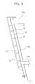
- FIG. 3 is a cross-sectional view showing one side of a combustion vessel of FIG. 2 .
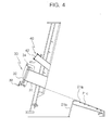
- FIG. 4 is a cross-sectional view showing the other side of a combustion vessel of FIG. 2 .
- FIG. 5 is a cross-sectional view showing a fuel supply unit of FIG. 2 .
- a combustion apparatus includes a combustion vessel 10 that burns a fuel therein and generates combustion gases of high temperature generated by combustion, and collects heat from the high temperature combustion gases using a boiler.
- the combustion vessel 10 is formed in a cylindrical shape, and contains and burns a solid fuel therein(the solid fuel in the present invention indicates all solid-type fuels including RDF, RPF, wood pellet, coal, and so on).
- the combustion vessel 10 includes: a combustion chamber 11 that is surrounded by an inner wall of the combustion vessel 10 to thus burn a fuel; a cooling chamber 13 that cools the inner wall of the combustion chamber 11; and a lateral combustion air supply chamber 15 that is formed at the side surface of the combustion chamber 11 in order to supply air necessary for combustion supplied from the outside for the combustion chamber 11.
- the cooling chamber 13 plays a role of lowering temperature of the inner wall 12 that continues to contact the hot combustion gases of high temperature.
- the cooling chamber 13 is formed in a space formed between the inner wall 12 of the cylindrical combustion vessel 10 and an intermediate wall 14 that is formed to be spaced apart from an outer side of the inner wall 12 of the cylindrical combustion vessel 10 whose inner diameter is narrowed upwards.
- a cooling water inlet 14a and a cooling water outlet 14b through which cooling water flows in and out, respectively, are formed at lower and upper sides of the intermediate wall 14.
- the cooling water inlet 14a is formed in a tangential direction with respect to the intermediate wall 14 of the cylindrical combustion vessel 10.
- a spirally shaped cooling water guide plate 13a is provided at the inner side of the intermediate wall 14 in the cooling chamber 13 so that the cooling water introduced via the cooling water inlet 14a turns and rises up along the cooling water guide plate 13a and discharged through the cooling water outlet 14b that is formed at the upper side of the intermediate wall 14.
- the cooling water discharged through the cooling water outlet 14b is introduced into a boiler(not shown) via connection tube, so as to be used to collect heat from the hot combustion gases of high temperature that has been generated in the combustion chamber 11.
- the lateral combustion air supply chamber 15 is formed in a space formed between the intermediate wall 14 of the cylindrical combustion vessel 10 and an outer wall 16 that is formed to be spaced apart from an outer side of the intermediate wall 14.
- a combustion air supply inlet 16a through which air necessary for combustion is supplied from the outside is formed at an upper side of the outer wall 16.
- the lower portion 12a of the lateral combustion air supply chamber 15 is opened.
- the combustion air supply inlet 16a is formed in a tangential direction with respect to the cylindrical outer wall 16. Accordingly, the air supplied through the combustion air supply inlet 16a turns and falls down in the inside of the lateral combustion air supply chamber 15, and then is supplied into the combustion chamber 11 via an opened lower portion 12a of the lateral combustion air supply chamber 15.
- a nozzle-cleaning manhole 30 and an observation scope 40 are formed at the outside of the combustion vessel 10.
- the nozzle-cleaning manhole 30 and the observation scope 40 are for cleaning air feed nozzles 21 c when the air feed nozzles 21 c are blocked by solid fuel.
- the nozzle-cleaning manhole 30 includes a cylindrical body 31 that communicates with the combustion chamber 11 and is formed at the outside of the combustion vessel 10 to be directed to the extension line of the upper surface of the diameter enlargement portion 21 a of a fuel supply tube 21; a cover 32 that is pivotably engaged to an outer end of the cylindrical body 31; and a handle 33 that locks/unlocks the cover 32 to the cylindrical body 31.
- the cover 32 is pivotably connected in a pivot shaft 34 in a bracket of one end of the cylindrical body 31, and the handle 33 that is screw-engaged in the bracket of the other end of the cylindrical body 31 is rotated to lock or unlock the cover 32 to the cylindrical body 31.
- the observation scope 40 is formed at the upper side of the nozzle-cleaning manhole 30 outside of the combustion vessel 10, and includes a cylindrical body 41 that is directed to the diameter enlargement portion 21 a, and a window 42 that is installed at the outer end of the cylindrical body 41.
- the upper portion of the combustion vessel 10 is opened in order to exhaust the hot combustion gases of high temperature that are generated by burning a fuel, and the exhausted hot combustion gases are introduced into the boiler through a combustion gas discharge tube (not shown) in order to collect heat.
- the boiler collects heat from the hot combustion gases and thus obtains hot steam of high temperature.
- an ash ejection outlet 19 is formed at the lower edge of the combustion vessel 10 to thereby discharge ashes of the burnt solid fuels.
- a rotary type fire grate 17 (grate is plate for loading the solid fuel in the top surface thereof) is rotatably installed at the lower portion of the combustion chamber 11.
- the rotary type fire grate 17 is made in the form of a disc, and plays a role of burning solid fuels loaded in the top surface thereof.
- the rotary type fire grate 17 is sloped downwards from the center thereof to the outer side inflection point thereof and then is sloped upwards from the outer side inflection point to the outermost side thereof. Accordingly, both side cross-sections of the rotary type fire grate 17 are formed into a V-shaped form.
- a fuel supply unit 20 for supplying solid fuels for the rotary type fire grate 17 is formed at the center of the rotary type fire grate 17.
- a fuel inlet 24 is formed at one side of the lower portion of the fuel supply unit 20, and a fuel supply tube 21 is provided in the fuel supply unit 20 to thereby supply solid fuels into the combustion chamber 11 by a transfer screw 22.
- a lower combustion air supply tube 23 whose diameter is larger than that of the fuel supply tube 21 and that is formed in the form of a concentric circle is formed at the outer side of the fuel supply tube 21, in which the lower combustion air supply tube 23 supplies combustion air from the lower portion of the combustion chamber 11 into the inside of the combustion chamber 11 by an air supply unit 25 such as a ring blower.
- An upper end portion that is protrudingly formed from the fuel supply tube 21 into the combustion chamber 11 includes: a diameter enlargement portion 21 a whose diameter gradually becomes larger upwards; and a slope guide portion 21 b that is bent downwards from the end portion of the diameter enlargement portion 21 a and is formed slantly downwards.
- the diameter enlargement portion 21 a and the slope guide portion 21 b make the fuels be supplied to the fire grate 17 more stably.
- a number of air feed nozzles 21 c are formed at the diameter enlargement portion 21 a so that the combustion air supplied from the lower combustion air supply tube 23 is introduced into the combustion chamber 11.
- an upper end portion that is protrudingly formed from the lower combustion air supply tube 23 into the combustion chamber 11 includes an air feed diameter enlargement portion 23a whose diameter gradually grows larger upwards and that is positioned at the lower side of the diameter enlargement portion 21 a of the fuel supply tube 21, and an upper end of the air feed diameter enlargement portion 23a is closed by the slope guide portion 21 b of the fuel supply tube 21.
- the combustion air supplied through the lower combustion air supply tube 23 is guided by the air feed diameter enlargement portion 23a and then is supplied to the bottom of the fuels through a number of the air feed nozzles 21 c that are formed at the diameter enlargement portion 21 a of the fuel supply tube 21 that is formed at the upper side thereof.
- an air supply unit 25 such as a ring blower may be provided at the other side of the lower portion of the fuel supply tube 21, so that combustion air can be supplied through the fuel supply tube 21 in order to prevent the solid fuels that are burnt in the combustion chamber 11 from being reversed into the solid fuels that exist in the fuel supply tube 21.
- the solid fuels are supplied to the center of the upper surface of the rotary type fire grate 17 by the fuel supply tube 21, and the combustion air is directly supplied to the bottom of the solid fuels through the air feed nozzles 21 c that are formed at the diameter enlargement portion 21 a of the fuel supply tube 21.
- a transfer screw 22 that is formed in the fuel supply tube 21 and thus transfers the fuels into the combustion chamber 11 includes a screw shaft 22d and screw blades 22e that are formed on the screw shaft 22d.
- the transfer screw 22 rotates by a motor(not shown) and transfers the fuels.
- a horizontal fuel supply member 22a is provided at the upper end of the screw shaft 22d and is rotated together with the screw shaft 22d.
- the horizontal fuel supply member 22a is extended to the outside of the fuel supply tube 21, and is protrudingly formed in the combustion chamber 11.
- the horizontal fuel supply member 22a includes: an extension shaft 22f that is extended from the screw shaft 22d and is rotated with the screw shaft 22d, a radial fuel supply element 22b that is formed at the circumference of the extension shaft 22f, and a fuel height control bracket 22c that is installed at the upper end of the extension shaft 22f.
- the radial fuel supply element 22b that radially supplies the fuels that are supplied through the fuel supply tube 21 into the combustion chamber 1 1 is formed by a certain length in the length direction of the transfer screw 22.
- the radial fuel supply element 22b is protrudingly formed perpendicularly from the axial direction of the extension shaft 22f and thus is rotated together with a transfer screw 22, to thereby radially supply the fuels that are raised up through the fuel supply tube 21 into the combustion chamber 11.
- the solid fuels that are supplied from the fuel supply tube 21 are radially consistently supplied into the combustion chamber 11, to thereby prevent clinkers from blocking the air feed nozzles 21 c.
- the fuel height control bracket 22c that is protrudingly formed perpendicularly from the axial direction of the extension shaft 22f is installed at the end of the extension shaft 22f that is protrudingly formed in the combustion chamber 11.
- the fuel height control bracket 22c has a conical shape at the upper portion thereof, and has a structure that the diameter of the lower portion thereof is the larger than that of the extension shaft 22f so that the fuels do not move upwards continuously but are pushed outwards. Accordingly, height of the fuels that are loaded on the diameter enlargement portion 21 a and the upper portion of the fire grate 17 in the combustion chamber 11 can be properly controlled, to thereby ensure perfect combustion of fuels.
- a certain amount of solid fuels are supplied into a combustion chamber 1 1 from a fuel hopper (not shown) by the rotation of a transfer screw 22 that is installed in a fuel supply tube 21.
- a radial fuel supply element 22b of the horizontal fuel supply member 22a that is protruded into the combustion chamber 11 is rotated together with the screw shaft 22d to radially supply the fuels that are raised up through the fuel supply tube 21 into the combustion chamber 11.
- the fuel supply unit 20 makes fuels whose particles are small and light rise up and be burnt by combustion air that is supplied from the air feed nozzles 21 c, and makes fuels whose particles are relatively large and heavy radially consistently supplied into the combustion chamber 11 in the neighbourhood of the fuel supply tube 21 by the radial fuel supply element 22b, to thereby prevent clinkers from blocking the air feed nozzles 21 c.
- the present invention can solve conventional problems of incompletely burning fuels that are continuously piled up to the upper portion of the fuel supply tube since the fuels contact combustion air in a small area, and preventing the fuels that are not discharged to the outer side of the fuel supply tube from being produced into clinkers that prevent the fuels from being burnt.
- the solid fuels supplied into the combustion chamber 11 are preheated and ignited by a preheating burner (not shown) and an ignition burner (not shown), to then be burnt.
- the solid fuels supplied to the upper side of the rotary type fire grate 17 are burnt and moves to the edge of the rotary type fire grate 17 due to a continuous supply of fuels as time passes.
- the fuels whose portion is changed into liquid-phase fuels as the solid fuels are burnt, stay and are burnt in a V-shaped gully portion whose cross-section is the same as that of the rotary type fire grate 17.
- cooling water is introduced into a cooling chamber 13 through a cooling water inlet 14a of the cooling chamber 13 that is formed at the outer circumference of the inner wall 12 of the combustion chamber 11 and the introduced cooling water is rotated and raised up by a cooling water guide plate 13a to thereby cool the inner wall 12 to then be discharged through a cooling water outlet 14b.
- the cooling water discharged from the cooling chamber 13 is stored in a boiler feed water tank via a connection tube, and then is introduced into a boiler, to thereby collect heat from the hot combustion gases by a heat exchanging process.
- the combustion apparatus includes the cooling chamber 13 that is formed at the outer circumference of the inner wall 12 of the combustion chamber 11, to thereby prevent durability from being lowered due to an excessive temperature rise of the inner wall 12 of the combustion chamber 11.
- the cooling water is preheated through the heat exchanging process with respect to the inner wall 12 of the cooling chamber 13, and then is introduced into the boiler again, to thereby collect heat from the hot combustion gases that have been generated by the combustion apparatus according to the present invention, and to thus prevent durability from being lowered due to deform, deterioration or crack that may occur at the inner wall 12 of the combustion chamber 11 that is continuously exposed to the hot combustion gases, and simultaneously avoid an unnecessary loss of heat to accordingly enhance a thermal efficiency.
- combustion air necessary for burning solid fuels is fed to the combustion chamber 11 through the lateral combustion air supply chamber 15 and the lower combustion air supply tube 23 from the outside.
- the combustion air supplied through the air supply inlet 16a that is formed in a tangential direction with respect to the upper portion of the outer wall 16 of the cylindrical combustion vessel 10 turns and falls down in the lateral combustion air supply chamber 15, to then be supplied into the combustion chamber 11 through the opened lower portion 12a of the lateral combustion air supply chamber 15.
- the combustion air is supplied while turning, in the lateral combustion air supply chamber 15, that is, at the lateral surface of the combustion chamber 11.
- the combustion chamber 11 is small in comparison with a case where combustion air is supplied in a straight line direction with respect to the fuels, the combustion air is directly in contact with most of the fuels, to thereby lower a manufacturing cost and enhance a thermal efficiency.
- the combustion air that is supplied by the lower combustion air supply tube 23 that is formed at the outer side of the fuel supply tube 21 is supplied into the combustion chamber 11 through the air feed nozzles 21 c that are formed at the diameter enlargement portion 21 a of the fuel supply tube 21, and thus is supplied to the lower portion of the solid fuels loaded in the combustion chamber 11. Accordingly, the outer portion of the solid fuels loaded in the combustion chamber 11 as well as the lower and inner portions of the solid fuels is also smoothly burnt, to thereby enhance combustion efficiency.
- the hot combustion gases of high temperature that has been generated by burning the solid fuels in the combustion chamber 11 are introduced into the boiler through the opened upper portion of the combustion chamber 11, and the hot combustion gases that have been supplied to the boiler are used to generate hot water or steam for an industrial purpose by a heat exchanging process.
- the air feed nozzles 21 c that are formed at the diameter enlargement portion 21 a of the fuel supply tube 21 can be blocked by solid fuel or ashes that have been produced when the solid fuels have been burnt.
- combustion air cannot be supplied to the bottom of the solid fuels, it results in lowering the combustion efficiency.
- the handle 33 of the nozzle-cleaning manhole 30 is rotated to unlock the cover 32 from the cylindrical body 31, and the cylindrical body 31 is opened by the rotation of the cover 32.
- the present invention provides the effect that prevents the combustion efficiency from being lowered, by removing the blocking of the air feed nozzles 21 c formed at the diameter enlargement portion 21 a of the fuel supply tube 21.
- the swirl flow is generated and is swirled in the combustion chamber 11
- most of the fuel may be contacted with the combustion air even though the combustion chamber 1 1 and the fire grate are small; therefore, it is possible to reduce the manufacturing cost and to design for complete combustion because the combustion air is continuously supplied directly to the solid fuel, at the same time, it is possible to increase the temperature of the combustion gas generated by the combustion of the fuel and to improve the thermal efficiency.
- the combustion apparatus includes the cooling chamber 13 that is formed at the outer circumference of the inner wall 12 of the combustion chamber 11, to thereby overcome the problem of the conventional incinerator and prevent durability from being lowered due to an excessive temperature rise of the inner wall of the combustion chamber.
- combustion apparatus As described above, an example of using solid fuels has been described in a combustion apparatus according to a preferred embodiment of the present invention.
- the combustion apparatus according to the present invention is not limited to the example of using the solid fuels but can be applied to examples of using gas fuels or liquid fuels.
Landscapes
- Engineering & Computer Science (AREA)
- Chemical & Material Sciences (AREA)
- Combustion & Propulsion (AREA)
- Mechanical Engineering (AREA)
- General Engineering & Computer Science (AREA)
- Physics & Mathematics (AREA)
- Thermal Sciences (AREA)
- Solid-Fuel Combustion (AREA)
- Gas Burners (AREA)
Applications Claiming Priority (1)
| Application Number | Priority Date | Filing Date | Title |
|---|---|---|---|
| KR2020110006594U KR20130000688U (ko) | 2011-07-20 | 2011-07-20 | 연소효율이 향상되고 수리 및 청소가 용이한 연소장치 |
Publications (3)
| Publication Number | Publication Date |
|---|---|
| EP2549181A2 true EP2549181A2 (fr) | 2013-01-23 |
| EP2549181A3 EP2549181A3 (fr) | 2015-04-29 |
| EP2549181B1 EP2549181B1 (fr) | 2016-09-21 |
Family
ID=46419998
Family Applications (1)
| Application Number | Title | Priority Date | Filing Date |
|---|---|---|---|
| EP12174643.2A Active EP2549181B1 (fr) | 2011-07-20 | 2012-07-02 | Appareil de combustion avec efficacité améliorée |
Country Status (2)
| Country | Link |
|---|---|
| EP (1) | EP2549181B1 (fr) |
| KR (1) | KR20130000688U (fr) |
Cited By (3)
| Publication number | Priority date | Publication date | Assignee | Title |
|---|---|---|---|---|
| JP2015014376A (ja) * | 2013-07-03 | 2015-01-22 | 株式会社シンエイ | 燃焼装置 |
| CN104791769A (zh) * | 2015-04-24 | 2015-07-22 | 扬州斯大锅炉有限公司 | 一种燃烧烟气供应装置 |
| CN104930537A (zh) * | 2015-06-19 | 2015-09-23 | 裴韩佶 | 一种烟气再循环燃烧装置 |
Families Citing this family (1)
| Publication number | Priority date | Publication date | Assignee | Title |
|---|---|---|---|---|
| US10188091B2 (en) | 2017-06-01 | 2019-01-29 | alliance sports group, I.p. | Portable light and insect extermination device |
Family Cites Families (2)
| Publication number | Priority date | Publication date | Assignee | Title |
|---|---|---|---|---|
| KR100821124B1 (ko) * | 2007-11-16 | 2008-04-14 | 에너원 주식회사 | 열회수용 연소장치 |
| KR200445277Y1 (ko) * | 2008-09-03 | 2009-07-16 | 에너원 주식회사 | 열회수율 및 내구성이 향상된 연소장치 |
-
2011
- 2011-07-20 KR KR2020110006594U patent/KR20130000688U/ko not_active Ceased
-
2012
- 2012-07-02 EP EP12174643.2A patent/EP2549181B1/fr active Active
Non-Patent Citations (1)
| Title |
|---|
| None |
Cited By (5)
| Publication number | Priority date | Publication date | Assignee | Title |
|---|---|---|---|---|
| JP2015014376A (ja) * | 2013-07-03 | 2015-01-22 | 株式会社シンエイ | 燃焼装置 |
| CN104791769A (zh) * | 2015-04-24 | 2015-07-22 | 扬州斯大锅炉有限公司 | 一种燃烧烟气供应装置 |
| CN104930537A (zh) * | 2015-06-19 | 2015-09-23 | 裴韩佶 | 一种烟气再循环燃烧装置 |
| WO2016201740A1 (fr) * | 2015-06-19 | 2016-12-22 | 裴韩佶 | Appareil de combustion à recirculation de gaz de combustion |
| CN104930537B (zh) * | 2015-06-19 | 2017-06-20 | 裴韩佶 | 一种烟气再循环燃烧装置 |
Also Published As
| Publication number | Publication date |
|---|---|
| EP2549181B1 (fr) | 2016-09-21 |
| KR20130000688U (ko) | 2013-01-30 |
| EP2549181A3 (fr) | 2015-04-29 |
Similar Documents
| Publication | Publication Date | Title |
|---|---|---|
| US20120017849A1 (en) | Combustion apparatus with improved thermal efficiency | |
| KR100821124B1 (ko) | 열회수용 연소장치 | |
| AU2020342700B2 (en) | Biomass heating system, as well as its components | |
| KR200455315Y1 (ko) | 열회수율 및 내구성이 향상된 연소장치 | |
| KR101228345B1 (ko) | 연소효율이 향상되는 연소장치 | |
| KR200445277Y1 (ko) | 열회수율 및 내구성이 향상된 연소장치 | |
| KR101280857B1 (ko) | 연소효율이 향상되는 연소장치 | |
| EP2549181B1 (fr) | Appareil de combustion avec efficacité améliorée | |
| EP2753878B1 (fr) | Dispositif de combustion et procédé pour la combustion de combustible solide granulaire | |
| KR101209022B1 (ko) | 열회수율이 향상된 열회수시스템 및 이를 이용한 열병합 발전시스템 | |
| CN106224974A (zh) | 垃圾焚烧处理系统 | |
| CN102345850B (zh) | 具有改进的热回收率的热回收系统及利用该系统的热电联产系统 | |
| KR101080928B1 (ko) | 열효율이 향상된 연소장치 | |
| KR20130001470U (ko) | 내구성 및 연소효율이 향상되는 연소장치 | |
| KR200464404Y1 (ko) | 열회수율 및 내구성이 향상된 연소장치 | |
| KR101017700B1 (ko) | 열효율이 향상된 연소장치 | |
| KR101399977B1 (ko) | 클링커 제거장치를 구비한 연소장치 | |
| KR20210023095A (ko) | 원형스토커 열분해연소설비 | |
| KR200489378Y1 (ko) | 클링커제거장치를 구비한 연소기 | |
| KR20120117968A (ko) | 연소효율이 향상되는 연소장치 | |
| CN204829922U (zh) | 一种垃圾焚烧炉热利用装置 | |
| RU2798328C1 (ru) | Отопительная установка на биомассе, а также ее составные части | |
| JP3099224U (ja) | 木屑およびバイオマスペレット焚き全自動燃焼炉 | |
| JP2007147176A (ja) | 焼却装置 | |
| RU2607938C2 (ru) | Горелка с высокотемпературной топкой (гвтт) |
Legal Events
| Date | Code | Title | Description |
|---|---|---|---|
| PUAI | Public reference made under article 153(3) epc to a published international application that has entered the european phase |
Free format text: ORIGINAL CODE: 0009012 |
|
| 17P | Request for examination filed |
Effective date: 20120702 |
|
| AK | Designated contracting states |
Kind code of ref document: A2 Designated state(s): AL AT BE BG CH CY CZ DE DK EE ES FI FR GB GR HR HU IE IS IT LI LT LU LV MC MK MT NL NO PL PT RO RS SE SI SK SM TR |
|
| AX | Request for extension of the european patent |
Extension state: BA ME |
|
| PUAL | Search report despatched |
Free format text: ORIGINAL CODE: 0009013 |
|
| AK | Designated contracting states |
Kind code of ref document: A3 Designated state(s): AL AT BE BG CH CY CZ DE DK EE ES FI FR GB GR HR HU IE IS IT LI LT LU LV MC MK MT NL NO PL PT RO RS SE SI SK SM TR |
|
| AX | Request for extension of the european patent |
Extension state: BA ME |
|
| RIC1 | Information provided on ipc code assigned before grant |
Ipc: F23B 40/04 20060101ALI20150325BHEP Ipc: F23B 30/04 20060101AFI20150325BHEP Ipc: F23M 5/08 20060101ALI20150325BHEP |
|
| RBV | Designated contracting states (corrected) |
Designated state(s): AL AT BE BG CH CY CZ DE DK EE ES FI FR GB GR HR HU IE IS IT LI LT LU LV MC MK MT NL NO PL PT RO RS SE SI SK SM TR |
|
| GRAP | Despatch of communication of intention to grant a patent |
Free format text: ORIGINAL CODE: EPIDOSNIGR1 |
|
| INTG | Intention to grant announced |
Effective date: 20160418 |
|
| GRAS | Grant fee paid |
Free format text: ORIGINAL CODE: EPIDOSNIGR3 |
|
| GRAA | (expected) grant |
Free format text: ORIGINAL CODE: 0009210 |
|
| AK | Designated contracting states |
Kind code of ref document: B1 Designated state(s): AL AT BE BG CH CY CZ DE DK EE ES FI FR GB GR HR HU IE IS IT LI LT LU LV MC MK MT NL NO PL PT RO RS SE SI SK SM TR |
|
| REG | Reference to a national code |
Ref country code: GB Ref legal event code: FG4D |
|
| REG | Reference to a national code |
Ref country code: CH Ref legal event code: EP |
|
| REG | Reference to a national code |
Ref country code: AT Ref legal event code: REF Ref document number: 831357 Country of ref document: AT Kind code of ref document: T Effective date: 20161015 |
|
| REG | Reference to a national code |
Ref country code: IE Ref legal event code: FG4D |
|
| REG | Reference to a national code |
Ref country code: DE Ref legal event code: R096 Ref document number: 602012023239 Country of ref document: DE |
|
| REG | Reference to a national code |
Ref country code: CH Ref legal event code: NV Representative=s name: ISLER AND PEDRAZZINI AG, CH |
|
| REG | Reference to a national code |
Ref country code: LT Ref legal event code: MG4D Ref country code: NL Ref legal event code: MP Effective date: 20160921 |
|
| PG25 | Lapsed in a contracting state [announced via postgrant information from national office to epo] |
Ref country code: NO Free format text: LAPSE BECAUSE OF FAILURE TO SUBMIT A TRANSLATION OF THE DESCRIPTION OR TO PAY THE FEE WITHIN THE PRESCRIBED TIME-LIMIT Effective date: 20161221 Ref country code: FI Free format text: LAPSE BECAUSE OF FAILURE TO SUBMIT A TRANSLATION OF THE DESCRIPTION OR TO PAY THE FEE WITHIN THE PRESCRIBED TIME-LIMIT Effective date: 20160921 Ref country code: LT Free format text: LAPSE BECAUSE OF FAILURE TO SUBMIT A TRANSLATION OF THE DESCRIPTION OR TO PAY THE FEE WITHIN THE PRESCRIBED TIME-LIMIT Effective date: 20160921 Ref country code: RS Free format text: LAPSE BECAUSE OF FAILURE TO SUBMIT A TRANSLATION OF THE DESCRIPTION OR TO PAY THE FEE WITHIN THE PRESCRIBED TIME-LIMIT Effective date: 20160921 |
|
| REG | Reference to a national code |
Ref country code: AT Ref legal event code: MK05 Ref document number: 831357 Country of ref document: AT Kind code of ref document: T Effective date: 20160921 |
|
| PG25 | Lapsed in a contracting state [announced via postgrant information from national office to epo] |
Ref country code: GR Free format text: LAPSE BECAUSE OF FAILURE TO SUBMIT A TRANSLATION OF THE DESCRIPTION OR TO PAY THE FEE WITHIN THE PRESCRIBED TIME-LIMIT Effective date: 20161222 Ref country code: SE Free format text: LAPSE BECAUSE OF FAILURE TO SUBMIT A TRANSLATION OF THE DESCRIPTION OR TO PAY THE FEE WITHIN THE PRESCRIBED TIME-LIMIT Effective date: 20160921 Ref country code: NL Free format text: LAPSE BECAUSE OF FAILURE TO SUBMIT A TRANSLATION OF THE DESCRIPTION OR TO PAY THE FEE WITHIN THE PRESCRIBED TIME-LIMIT Effective date: 20160921 Ref country code: LV Free format text: LAPSE BECAUSE OF FAILURE TO SUBMIT A TRANSLATION OF THE DESCRIPTION OR TO PAY THE FEE WITHIN THE PRESCRIBED TIME-LIMIT Effective date: 20160921 |
|
| PG25 | Lapsed in a contracting state [announced via postgrant information from national office to epo] |
Ref country code: RO Free format text: LAPSE BECAUSE OF FAILURE TO SUBMIT A TRANSLATION OF THE DESCRIPTION OR TO PAY THE FEE WITHIN THE PRESCRIBED TIME-LIMIT Effective date: 20160921 Ref country code: EE Free format text: LAPSE BECAUSE OF FAILURE TO SUBMIT A TRANSLATION OF THE DESCRIPTION OR TO PAY THE FEE WITHIN THE PRESCRIBED TIME-LIMIT Effective date: 20160921 |
|
| REG | Reference to a national code |
Ref country code: FR Ref legal event code: PLFP Year of fee payment: 6 |
|
| PG25 | Lapsed in a contracting state [announced via postgrant information from national office to epo] |
Ref country code: CZ Free format text: LAPSE BECAUSE OF FAILURE TO SUBMIT A TRANSLATION OF THE DESCRIPTION OR TO PAY THE FEE WITHIN THE PRESCRIBED TIME-LIMIT Effective date: 20160921 Ref country code: IS Free format text: LAPSE BECAUSE OF FAILURE TO SUBMIT A TRANSLATION OF THE DESCRIPTION OR TO PAY THE FEE WITHIN THE PRESCRIBED TIME-LIMIT Effective date: 20170121 Ref country code: BE Free format text: LAPSE BECAUSE OF FAILURE TO SUBMIT A TRANSLATION OF THE DESCRIPTION OR TO PAY THE FEE WITHIN THE PRESCRIBED TIME-LIMIT Effective date: 20160921 Ref country code: AT Free format text: LAPSE BECAUSE OF FAILURE TO SUBMIT A TRANSLATION OF THE DESCRIPTION OR TO PAY THE FEE WITHIN THE PRESCRIBED TIME-LIMIT Effective date: 20160921 Ref country code: PL Free format text: LAPSE BECAUSE OF FAILURE TO SUBMIT A TRANSLATION OF THE DESCRIPTION OR TO PAY THE FEE WITHIN THE PRESCRIBED TIME-LIMIT Effective date: 20160921 Ref country code: BG Free format text: LAPSE BECAUSE OF FAILURE TO SUBMIT A TRANSLATION OF THE DESCRIPTION OR TO PAY THE FEE WITHIN THE PRESCRIBED TIME-LIMIT Effective date: 20161221 Ref country code: PT Free format text: LAPSE BECAUSE OF FAILURE TO SUBMIT A TRANSLATION OF THE DESCRIPTION OR TO PAY THE FEE WITHIN THE PRESCRIBED TIME-LIMIT Effective date: 20170123 Ref country code: SK Free format text: LAPSE BECAUSE OF FAILURE TO SUBMIT A TRANSLATION OF THE DESCRIPTION OR TO PAY THE FEE WITHIN THE PRESCRIBED TIME-LIMIT Effective date: 20160921 Ref country code: SM Free format text: LAPSE BECAUSE OF FAILURE TO SUBMIT A TRANSLATION OF THE DESCRIPTION OR TO PAY THE FEE WITHIN THE PRESCRIBED TIME-LIMIT Effective date: 20160921 Ref country code: ES Free format text: LAPSE BECAUSE OF FAILURE TO SUBMIT A TRANSLATION OF THE DESCRIPTION OR TO PAY THE FEE WITHIN THE PRESCRIBED TIME-LIMIT Effective date: 20160921 |
|
| REG | Reference to a national code |
Ref country code: DE Ref legal event code: R097 Ref document number: 602012023239 Country of ref document: DE |
|
| PG25 | Lapsed in a contracting state [announced via postgrant information from national office to epo] |
Ref country code: IT Free format text: LAPSE BECAUSE OF FAILURE TO SUBMIT A TRANSLATION OF THE DESCRIPTION OR TO PAY THE FEE WITHIN THE PRESCRIBED TIME-LIMIT Effective date: 20160921 |
|
| PLBE | No opposition filed within time limit |
Free format text: ORIGINAL CODE: 0009261 |
|
| STAA | Information on the status of an ep patent application or granted ep patent |
Free format text: STATUS: NO OPPOSITION FILED WITHIN TIME LIMIT |
|
| PG25 | Lapsed in a contracting state [announced via postgrant information from national office to epo] |
Ref country code: DK Free format text: LAPSE BECAUSE OF FAILURE TO SUBMIT A TRANSLATION OF THE DESCRIPTION OR TO PAY THE FEE WITHIN THE PRESCRIBED TIME-LIMIT Effective date: 20160921 |
|
| 26N | No opposition filed |
Effective date: 20170622 |
|
| PG25 | Lapsed in a contracting state [announced via postgrant information from national office to epo] |
Ref country code: SI Free format text: LAPSE BECAUSE OF FAILURE TO SUBMIT A TRANSLATION OF THE DESCRIPTION OR TO PAY THE FEE WITHIN THE PRESCRIBED TIME-LIMIT Effective date: 20160921 |
|
| REG | Reference to a national code |
Ref country code: IE Ref legal event code: MM4A |
|
| PG25 | Lapsed in a contracting state [announced via postgrant information from national office to epo] |
Ref country code: IE Free format text: LAPSE BECAUSE OF NON-PAYMENT OF DUE FEES Effective date: 20170702 |
|
| PG25 | Lapsed in a contracting state [announced via postgrant information from national office to epo] |
Ref country code: LU Free format text: LAPSE BECAUSE OF NON-PAYMENT OF DUE FEES Effective date: 20170702 |
|
| REG | Reference to a national code |
Ref country code: FR Ref legal event code: PLFP Year of fee payment: 7 |
|
| PG25 | Lapsed in a contracting state [announced via postgrant information from national office to epo] |
Ref country code: MT Free format text: LAPSE BECAUSE OF NON-PAYMENT OF DUE FEES Effective date: 20170702 |
|
| PG25 | Lapsed in a contracting state [announced via postgrant information from national office to epo] |
Ref country code: AL Free format text: LAPSE BECAUSE OF FAILURE TO SUBMIT A TRANSLATION OF THE DESCRIPTION OR TO PAY THE FEE WITHIN THE PRESCRIBED TIME-LIMIT Effective date: 20160921 |
|
| REG | Reference to a national code |
Ref country code: DE Ref legal event code: R082 Ref document number: 602012023239 Country of ref document: DE Representative=s name: PATENTANWAELTE VOLLMANN HEMMER LINDFELD PARTNE, DE Ref country code: DE Ref legal event code: R081 Ref document number: 602012023239 Country of ref document: DE Owner name: ENERONE INC., GUNSAN-SI, KR Free format text: FORMER OWNER: KIM, SANG KWON, SEOUL, KR |
|
| REG | Reference to a national code |
Ref country code: CH Ref legal event code: PUE Owner name: ENERONE INC., KR Free format text: FORMER OWNER: KIM, SANG KWON, KR |
|
| REG | Reference to a national code |
Ref country code: GB Ref legal event code: 732E Free format text: REGISTERED BETWEEN 20190523 AND 20190529 |
|
| PG25 | Lapsed in a contracting state [announced via postgrant information from national office to epo] |
Ref country code: HU Free format text: LAPSE BECAUSE OF FAILURE TO SUBMIT A TRANSLATION OF THE DESCRIPTION OR TO PAY THE FEE WITHIN THE PRESCRIBED TIME-LIMIT; INVALID AB INITIO Effective date: 20120702 Ref country code: MC Free format text: LAPSE BECAUSE OF FAILURE TO SUBMIT A TRANSLATION OF THE DESCRIPTION OR TO PAY THE FEE WITHIN THE PRESCRIBED TIME-LIMIT Effective date: 20160921 |
|
| PG25 | Lapsed in a contracting state [announced via postgrant information from national office to epo] |
Ref country code: CY Free format text: LAPSE BECAUSE OF NON-PAYMENT OF DUE FEES Effective date: 20160921 |
|
| PG25 | Lapsed in a contracting state [announced via postgrant information from national office to epo] |
Ref country code: MK Free format text: LAPSE BECAUSE OF FAILURE TO SUBMIT A TRANSLATION OF THE DESCRIPTION OR TO PAY THE FEE WITHIN THE PRESCRIBED TIME-LIMIT Effective date: 20160921 |
|
| PG25 | Lapsed in a contracting state [announced via postgrant information from national office to epo] |
Ref country code: TR Free format text: LAPSE BECAUSE OF FAILURE TO SUBMIT A TRANSLATION OF THE DESCRIPTION OR TO PAY THE FEE WITHIN THE PRESCRIBED TIME-LIMIT Effective date: 20160921 |
|
| PG25 | Lapsed in a contracting state [announced via postgrant information from national office to epo] |
Ref country code: HR Free format text: LAPSE BECAUSE OF FAILURE TO SUBMIT A TRANSLATION OF THE DESCRIPTION OR TO PAY THE FEE WITHIN THE PRESCRIBED TIME-LIMIT Effective date: 20160921 |
|
| PGFP | Annual fee paid to national office [announced via postgrant information from national office to epo] |
Ref country code: DE Payment date: 20250728 Year of fee payment: 14 |
|
| PGFP | Annual fee paid to national office [announced via postgrant information from national office to epo] |
Ref country code: GB Payment date: 20250722 Year of fee payment: 14 |
|
| PGFP | Annual fee paid to national office [announced via postgrant information from national office to epo] |
Ref country code: FR Payment date: 20250723 Year of fee payment: 14 |
|
| PGFP | Annual fee paid to national office [announced via postgrant information from national office to epo] |
Ref country code: CH Payment date: 20250801 Year of fee payment: 14 |