EP2549188A2 - Insert pour chambre à combustion de moteur à turbine à gaz - Google Patents
Insert pour chambre à combustion de moteur à turbine à gaz Download PDFInfo
- Publication number
- EP2549188A2 EP2549188A2 EP12176894A EP12176894A EP2549188A2 EP 2549188 A2 EP2549188 A2 EP 2549188A2 EP 12176894 A EP12176894 A EP 12176894A EP 12176894 A EP12176894 A EP 12176894A EP 2549188 A2 EP2549188 A2 EP 2549188A2
- Authority
- EP
- European Patent Office
- Prior art keywords
- insert
- heat shield
- combustor
- shield panel
- recited
- Prior art date
- Legal status (The legal status is an assumption and is not a legal conclusion. Google has not performed a legal analysis and makes no representation as to the accuracy of the status listed.)
- Granted
Links
Images



Classifications
-
- F—MECHANICAL ENGINEERING; LIGHTING; HEATING; WEAPONS; BLASTING
- F23—COMBUSTION APPARATUS; COMBUSTION PROCESSES
- F23R—GENERATING COMBUSTION PRODUCTS OF HIGH PRESSURE OR HIGH VELOCITY, e.g. GAS-TURBINE COMBUSTION CHAMBERS
- F23R3/00—Continuous combustion chambers using liquid or gaseous fuel
- F23R3/002—Wall structures
-
- F—MECHANICAL ENGINEERING; LIGHTING; HEATING; WEAPONS; BLASTING
- F23—COMBUSTION APPARATUS; COMBUSTION PROCESSES
- F23R—GENERATING COMBUSTION PRODUCTS OF HIGH PRESSURE OR HIGH VELOCITY, e.g. GAS-TURBINE COMBUSTION CHAMBERS
- F23R3/00—Continuous combustion chambers using liquid or gaseous fuel
- F23R3/007—Continuous combustion chambers using liquid or gaseous fuel constructed mainly of ceramic components
-
- F—MECHANICAL ENGINEERING; LIGHTING; HEATING; WEAPONS; BLASTING
- F23—COMBUSTION APPARATUS; COMBUSTION PROCESSES
- F23R—GENERATING COMBUSTION PRODUCTS OF HIGH PRESSURE OR HIGH VELOCITY, e.g. GAS-TURBINE COMBUSTION CHAMBERS
- F23R3/00—Continuous combustion chambers using liquid or gaseous fuel
- F23R3/02—Continuous combustion chambers using liquid or gaseous fuel characterised by the air-flow or gas-flow configuration
- F23R3/04—Air inlet arrangements
- F23R3/06—Arrangement of apertures along the flame tube
-
- F—MECHANICAL ENGINEERING; LIGHTING; HEATING; WEAPONS; BLASTING
- F23—COMBUSTION APPARATUS; COMBUSTION PROCESSES
- F23R—GENERATING COMBUSTION PRODUCTS OF HIGH PRESSURE OR HIGH VELOCITY, e.g. GAS-TURBINE COMBUSTION CHAMBERS
- F23R2900/00—Special features of, or arrangements for continuous combustion chambers; Combustion processes therefor
- F23R2900/03042—Film cooled combustion chamber walls or domes
-
- Y—GENERAL TAGGING OF NEW TECHNOLOGICAL DEVELOPMENTS; GENERAL TAGGING OF CROSS-SECTIONAL TECHNOLOGIES SPANNING OVER SEVERAL SECTIONS OF THE IPC; TECHNICAL SUBJECTS COVERED BY FORMER USPC CROSS-REFERENCE ART COLLECTIONS [XRACs] AND DIGESTS
- Y02—TECHNOLOGIES OR APPLICATIONS FOR MITIGATION OR ADAPTATION AGAINST CLIMATE CHANGE
- Y02T—CLIMATE CHANGE MITIGATION TECHNOLOGIES RELATED TO TRANSPORTATION
- Y02T50/00—Aeronautics or air transport
- Y02T50/60—Efficient propulsion technologies, e.g. for aircraft
Definitions
- the present disclosure relates to a gas turbine engine combustor, and more particularly to a heat shield liner panel arrangement.
- a gas turbine engine includes a compressor to compress air that mixes with fuel and is channeled to a combustor wherein the mixture is ignited within a combustion chamber to generate hot combustion core gases.
- At least some combustors include combustor liners to channel the combustion gases to a turbine which extracts energy from the combustion core gases to power the compressor, as well as produce useful work to propel an aircraft in flight or to power a load, such as an electrical generator.
- Hot spots are raised temperature areas where component properties may rapidly degrade and thereby affect the durability of the component. Hot spots are conventionally combated with more cooling air, however, this may have a potential negative effect on combustor emissions, pattern factor, and profile.
- a combustor of a gas turbine engine includes a heat shield panel mounted to a support shell and an insert adjacent to the support shell and the heat shield panel, the insert exposed to a combustion chamber.
- a combustor of a gas turbine engine includes an insert adjacent to a support shell between a first heat shield panel and a second heat shield panel, the insert exposed to a combustion chamber.
- a method of protecting a combustor according to an exemplary aspect of the present disclosure includes locating an insert at a combustor hot spot adjacent to a support shell and a heat shield panel.
- FIG. 1 schematically illustrates a gas turbine engine 20.
- the gas turbine engine 20 is disclosed herein as a two-spool turbofan that generally incorporates a fan section 22, a compressor section 24, a combustor section 26 and a turbine section 28.
- Alternative engines might include an augmentor section (not shown) among other systems or features.
- the fan section 22 drives air along a bypass flowpath while the compressor section 24 drives air along a core flowpath for compression and communication into the combustor section 26 then expansion through the turbine section 28.
- FIG. 1 schematically illustrates a gas turbine engine 20.
- the gas turbine engine 20 is disclosed herein as a two-spool turbofan that generally incorporates a fan section 22, a compressor section 24, a combustor section 26 and a turbine section 28.
- Alternative engines might include an augmentor section (not shown) among other systems or features.
- the fan section 22 drives air along a bypass flowpath while the compressor section 24 drives air along a core flowpath for compression and communication into the combustor section 26
- the engine 20 generally includes a low speed spool 30 and a high speed spool 32 mounted for rotation about an engine central longitudinal axis A relative to an engine static structure 36 via several bearing systems 38. It should be understood that various bearing systems 38 at various locations may alternatively or additionally be provided.
- the low speed spool 30 generally includes an inner shaft 40 that interconnects a fan 42, a low pressure compressor 44 and a low pressure turbine 46.
- the inner shaft 40 is connected to the fan 42 through a geared architecture 48 to drive the fan 42 at a lower speed than the low speed spool 30.
- the high speed spool 32 includes an outer shaft 50 that interconnects a high pressure compressor 52 and high pressure turbine 54.
- a combustor 56 is arranged between the high pressure compressor 52 and the high pressure turbine 54.
- the inner shaft 40 and the outer shaft 50 are concentric to one-another and rotate about the engine central longitudinal axis A that is collinear with their longitudinal axes.
- the core airflow is compressed by the low pressure compressor 44 then the high pressure compressor 52, mixed and burned with fuel in the combustor 56, then expanded over the high pressure turbine 54 and low pressure turbine 46.
- the turbines 54, 46 rotationally drive the respective low speed spool 30 and high speed spool 32 in response to the expansion.
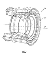
- the combustor 56 generally includes an outer shell 60 and an inner shell 62 within a combustor case 64.
- the outer shell 60 and the inner shell 62 line an annular combustion chamber 66 that extends toward and communicates with the turbine section 28.
- annular combustion chamber 66 that extends toward and communicates with the turbine section 28.
- an array of heat shield panels 68, 70 are respectively supported by the outer and inner shells 60, 62 around the combustion chamber 66.
- the array of heat shield panels 68 line the hot side of the outer shell 60, while the array of heat shield panels 70 line the hot side of the inner shell 62.
- the heat shield panels 68, 70 may be manufactured of, for example, a nickel based super alloy or ceramic material.
- Fastener assemblies F such as studs and nuts may be used to connect each of the heat shield panels 68, 70 to the respective inner and outer shells 60, 62 to provide a floatwall type array.
- the heat shield panels 68, 70 may be generally annular in shape and extend toward the turbine section 28. It should be understood that various numbers, types, and arrangements of heat shield panels may alternatively or additionally be provided.
- impingement cooling holes 72 penetrate through the inner and outer shells 60, 62 to communicate coolant, such as secondary cooling air, into the space between the inner and outer shells 60, 62 and the respective heat shield panels 68, 70.
- Film cooling holes 74 penetrate each of the heat shield panels 68, 70 to promote the formation of a film of cooling air.
- a multiple of dilution holes 76 (one shown) penetrate both the heat shield panels or floatwalls 68, 70 and the respective inner and outer support shells 60, 62, each along a common axis D to inject dilution air that facilitates combustion and the release of additional energy from the fuel.
- An insert 80 is located within or between any or each of the heat shield panels 68, 70 and at least partially sandwiched between heat shield panels 68, 70 and the respective shells 60, 62. It should be understood that the illustrated location of the insert 80 with respect to heat shield panels 68, 70 is merely one disclosed non-limiting embodiment and that other locations and heat shield panel arrangements may alternatively or additionally be provided.
- the insert 80 may be located at a combustor hot spot defined as a location where an incomplete mixing of fuel, i.e., a fuel rich region, may occur.
- the hot spot may be within a single heat shield panel 68, 70 or at an interface between a multiple of heat shield panels 68, 70.
- the insert 80 may be manufactured of a ceramic matrix composite material or high temperature metal alloy material that is more heat resistant than the heat shield panels 68, 70.
- the insert 80 may additionally include a thermal barrier coating layer 74 ( Figure 5 ) to minimize thermal conduction from shells 60, 62.
- This insert 80 may be approximately the size and shape of the potential hot spot and may replace a portion of the heat shield panel that may be otherwise inadequate to resist the elevated temperatures of the hot spot.
- the insert 80 includes a central area 82 that is generally flush or coplanar with a hot surface of the heat shield panels 68, 70 with flanges 84 which extend and are sandwiched between the respective heat shield panels 68, 70 and the respective support shell 60, 62.
- the central area 82 may be approximately 0.25 - 0.5 inches thick (6.4 - 12.7 mm).
- the step shape of the central area 82 and the flanges 84 retain the insert 80 as the flanges 84 are trapped between the respective heat shield panels 68, 70 and the shell 60, 62.
- the insert 80 may be positioned to operate as near to isothermal as possible so that hot spot stress is minimized
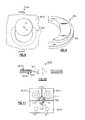
- insert 80A includes a retaining groove 86 in each of the flanges 84A that receives a respective lip 88 of the heat shield panels 68, 70.
- the retention interface of the groove 86 and lip 88 facilitates retention of the insert 80A throughout thermal excursions.
- insert 80B includes a generally open area 90 formed in the central area 82A, opposite a hot side thereof. That is, the open area 90 is under the hot side of the central area 82A to facilitate impingement cooling. Insert apertures 92 directed transverse to the impingement cooling holes 72 extend through flanges 84B.
- the generally open area 90 receives secondary cooling air from at least one impingement cooling hole 72 for communication through the insert apertures 90 then through the film cooling holes 74.
- the secondary cooling air may thereby be readily controlled with the size and arrangement of insert apertures 92 in the area adjacent to the adjacent heat shield panels 68, 70 which may heretofore have been subject to relatively high thermal excursions. Such an arrangement may be particularly advantageous adjacent to an edge of the heat shield panels 68, 70.
- an insert 80C is located adjacent to a dilution hole 76 offset from the dilution axis D defined thereby.
- the insert 80C is of a generally crescent shape ( Figure 9 ) with a step 102 in cross-section to fit at least partially define the dilution hole 76.
- the insert 80C is generally flush with the respective heat shield panel 68, 70 relative to the support shell 60, 62.
- a flange 84C defined by the step 102 extends between the respective heat shield panels 68, 70 and the support shell 60, 62 for retention therebetween (see Figure 10 ).
- the shape of the insert 80C essentially fills in a hot spot that typically may occur downstream of the dilution hole 76.
- an insert 80D, 80E may be of various shapes, such as, for example, rectangular, triangular, or other shapes, to fill in hot spot areas such as that may occur adjacent, for example, fuel nozzle injectors 114 ( Figure 2 ).
- the inserts 80D, 80D may additionally include tabs 116 that receive one or more fastener assemblies F for positive retention of the insert 80D, 80E and the heat shield panels 68, 70. It should be understood that various insert shapes may additionally or alternatively be provided to match the shape and location of a hot spot.
Landscapes
- Engineering & Computer Science (AREA)
- Chemical & Material Sciences (AREA)
- Combustion & Propulsion (AREA)
- Mechanical Engineering (AREA)
- General Engineering & Computer Science (AREA)
- Ceramic Engineering (AREA)
- Turbine Rotor Nozzle Sealing (AREA)
Applications Claiming Priority (1)
| Application Number | Priority Date | Filing Date | Title |
|---|---|---|---|
| US13/188,442 US9534783B2 (en) | 2011-07-21 | 2011-07-21 | Insert adjacent to a heat shield element for a gas turbine engine combustor |
Publications (3)
| Publication Number | Publication Date |
|---|---|
| EP2549188A2 true EP2549188A2 (fr) | 2013-01-23 |
| EP2549188A3 EP2549188A3 (fr) | 2015-05-13 |
| EP2549188B1 EP2549188B1 (fr) | 2016-11-16 |
Family
ID=46545276
Family Applications (1)
| Application Number | Title | Priority Date | Filing Date |
|---|---|---|---|
| EP12176894.9A Not-in-force EP2549188B1 (fr) | 2011-07-21 | 2012-07-18 | Insert pour chambre à combustion de moteur à turbine à gaz |
Country Status (2)
| Country | Link |
|---|---|
| US (1) | US9534783B2 (fr) |
| EP (1) | EP2549188B1 (fr) |
Cited By (9)
| Publication number | Priority date | Publication date | Assignee | Title |
|---|---|---|---|---|
| GB2510013A (en) * | 2012-10-15 | 2014-07-23 | Snecma | Heat shield for engine mounting arrangement |
| EP2930428A1 (fr) * | 2014-04-09 | 2015-10-14 | United Technologies Corporation | Ensemble paroi de chambre de combustion pour un moteur de turbine |
| EP3056813A1 (fr) * | 2015-02-12 | 2016-08-17 | Rolls-Royce Deutschland Ltd & Co KG | Joint pour un interstice marginal entre les bardeaux d'effusion d'une chambre de combustion de turbines a gaz |
| EP3099976A4 (fr) * | 2014-01-30 | 2017-03-01 | United Technologies Corporation | Flux de refroidissement pour un panneau principal dans une chambre de combustion de moteur à turbine à gaz |
| EP3306056A1 (fr) * | 2016-10-04 | 2018-04-11 | United Technologies Corporation | Bouclier thermique de bride |
| US9957816B2 (en) | 2014-05-29 | 2018-05-01 | General Electric Company | Angled impingement insert |
| US10422235B2 (en) | 2014-05-29 | 2019-09-24 | General Electric Company | Angled impingement inserts with cooling features |
| EP2735796B1 (fr) * | 2012-11-23 | 2020-01-01 | Ansaldo Energia IP UK Limited | Paroi située sur la trajectoire des gaz chauds d'une turbine à gaz et procédé pour améliorer le comportement de fonctionnment d'une turbine à gaz |
| US10690055B2 (en) | 2014-05-29 | 2020-06-23 | General Electric Company | Engine components with impingement cooling features |
Families Citing this family (28)
| Publication number | Priority date | Publication date | Assignee | Title |
|---|---|---|---|---|
| WO2014123850A1 (fr) * | 2013-02-06 | 2014-08-14 | United Technologies Corporation | Composant de turbine à gaz avec trous de film de refroidissement orientés vers l'amont |
| EP2954261B1 (fr) | 2013-02-08 | 2020-03-04 | United Technologies Corporation | Chambre de combustion de turbine à gaz |
| WO2014149108A1 (fr) | 2013-03-15 | 2014-09-25 | Graves Charles B | Agencement d'enceinte et de chemisage à dalles pour une chambre de combustion |
| WO2015009384A1 (fr) * | 2013-07-16 | 2015-01-22 | United Technologies Corporation | Turbine à gaz pourvue d'un panneau en céramique |
| US10808928B2 (en) | 2013-09-12 | 2020-10-20 | Raytheon Technologies Corporation | Boss for combustor panel |
| EP3071884B1 (fr) | 2013-11-18 | 2019-09-04 | United Technologies Corporation | Panneaux de chambre de combustion inclinés pour chambre de combustion de turbine à gaz |
| WO2015105654A1 (fr) | 2014-01-08 | 2015-07-16 | United Technologies Corporation | Joint de serrage pour cadre de turbine intermédiaire de turboréacteur |
| US10260365B2 (en) * | 2014-01-28 | 2019-04-16 | United Technologies Corporation | Seal for jet engine mid-turbine frame |
| EP3099921B1 (fr) * | 2014-01-28 | 2019-01-16 | United Technologies Corporation | Structure d'impact destinée à un carter dans la partie médiane d'une turbine de moteur à réaction |
| US10935241B2 (en) * | 2014-05-09 | 2021-03-02 | Raytheon Technologies Corporation | Additively manufactured hotspot portion of a turbine engine component having heat resistant properties and method of manufacture |
| US9625152B2 (en) * | 2014-06-03 | 2017-04-18 | Pratt & Whitney Canada Corp. | Combustor heat shield for a gas turbine engine |
| EP3040617B1 (fr) | 2014-12-31 | 2017-12-06 | Rolls-Royce North American Technologies, Inc. | Système de rétention pour ensembles de moteur à turbine à gaz |
| US20160258623A1 (en) * | 2015-03-05 | 2016-09-08 | United Technologies Corporation | Combustor and heat shield configurations for a gas turbine engine |
| US10094564B2 (en) * | 2015-04-17 | 2018-10-09 | Pratt & Whitney Canada Corp. | Combustor dilution hole cooling system |
| US10648669B2 (en) * | 2015-08-21 | 2020-05-12 | Rolls-Royce Corporation | Case and liner arrangement for a combustor |
| GB201518345D0 (en) * | 2015-10-16 | 2015-12-02 | Rolls Royce | Combustor for a gas turbine engine |
| US10935236B2 (en) | 2016-11-10 | 2021-03-02 | Raytheon Technologies Corporation | Non-planar combustor liner panel for a gas turbine engine combustor |
| US10935235B2 (en) | 2016-11-10 | 2021-03-02 | Raytheon Technologies Corporation | Non-planar combustor liner panel for a gas turbine engine combustor |
| US10655853B2 (en) | 2016-11-10 | 2020-05-19 | United Technologies Corporation | Combustor liner panel with non-linear circumferential edge for a gas turbine engine combustor |
| US10830433B2 (en) | 2016-11-10 | 2020-11-10 | Raytheon Technologies Corporation | Axial non-linear interface for combustor liner panels in a gas turbine combustor |
| IT201600130851A1 (it) * | 2016-12-23 | 2018-06-23 | Ansaldo Energia Spa | Piastrella termoisolante per camere di combustione di turbine a gas |
| US11187105B2 (en) * | 2017-02-09 | 2021-11-30 | General Electric Company | Apparatus with thermal break |
| US11402097B2 (en) | 2018-01-03 | 2022-08-02 | General Electric Company | Combustor assembly for a turbine engine |
| US11092339B2 (en) * | 2018-01-12 | 2021-08-17 | Raytheon Technologies Corporation | Apparatus and method for mitigating particulate accumulation on a component of a gas turbine |
| US11371703B2 (en) * | 2018-01-12 | 2022-06-28 | Raytheon Technologies Corporation | Apparatus and method for mitigating particulate accumulation on a component of a gas turbine |
| US11988145B2 (en) * | 2018-01-12 | 2024-05-21 | Rtx Corporation | Apparatus and method for mitigating airflow separation around engine combustor |
| US11536454B2 (en) | 2019-05-09 | 2022-12-27 | Pratt & Whitney Canada Corp. | Combustor wall assembly for gas turbine engine |
| JP2024091023A (ja) | 2022-12-23 | 2024-07-04 | 川崎重工業株式会社 | ガスタービンの燃焼器 |
Family Cites Families (48)
| Publication number | Priority date | Publication date | Assignee | Title |
|---|---|---|---|---|
| US4422300A (en) * | 1981-12-14 | 1983-12-27 | United Technologies Corporation | Prestressed combustor liner for gas turbine engine |
| US4567730A (en) | 1983-10-03 | 1986-02-04 | General Electric Company | Shielded combustor |
| US4655044A (en) | 1983-12-21 | 1987-04-07 | United Technologies Corporation | Coated high temperature combustor liner |
| US5277936A (en) * | 1987-11-19 | 1994-01-11 | United Technologies Corporation | Oxide containing MCrAlY-type overlay coatings |
| US5221096A (en) * | 1990-10-19 | 1993-06-22 | Allied-Signal Inc. | Stator and multiple piece seal |
| US5144793A (en) * | 1990-12-24 | 1992-09-08 | United Technologies Corporation | Integrated connector/airtube for a turbomachine's combustion chamber walls |
| US5435139A (en) * | 1991-03-22 | 1995-07-25 | Rolls-Royce Plc | Removable combustor liner for gas turbine engine combustor |
| US5687572A (en) * | 1992-11-02 | 1997-11-18 | Alliedsignal Inc. | Thin wall combustor with backside impingement cooling |
| GB2298267B (en) | 1995-02-23 | 1999-01-13 | Rolls Royce Plc | An arrangement of heat resistant tiles for a gas turbine engine combustor |
| GB2335470B (en) * | 1998-03-18 | 2002-02-13 | Rolls Royce Plc | A seal |
| WO1999047874A1 (fr) * | 1998-03-19 | 1999-09-23 | Siemens Aktiengesellschaft | Segment de paroi pour une chambre de combustion, et chambre de combustion |
| US6702549B2 (en) * | 2000-03-02 | 2004-03-09 | Siemens Aktiengesellschaft | Turbine installation |
| EP1130218A1 (fr) * | 2000-03-02 | 2001-09-05 | Siemens Aktiengesellschaft | Turbine avec joint d'étanchéitée entre les plateformes des stateurs |
| GB2361303B (en) * | 2000-04-14 | 2004-10-20 | Rolls Royce Plc | Wall structure for a gas turbine engine combustor |
| US6397603B1 (en) | 2000-05-05 | 2002-06-04 | The United States Of America As Represented By The Secretary Of The Air Force | Conbustor having a ceramic matrix composite liner |
| US6431825B1 (en) * | 2000-07-28 | 2002-08-13 | Alstom (Switzerland) Ltd | Seal between static turbine parts |
| EP1284390A1 (fr) | 2001-06-27 | 2003-02-19 | Siemens Aktiengesellschaft | Ensemble bouclier thermique pour un composant acheminant un gaz chaud, notamment pour des pièces de structure de turbines à gaz |
| EP1288601B1 (fr) * | 2001-08-28 | 2006-10-25 | Siemens Aktiengesellschaft | Brique de protection thermique ainsi que son utilisation dans une chambre de combustion |
| GB2380236B (en) * | 2001-09-29 | 2005-01-19 | Rolls Royce Plc | A wall structure for a combustion chamber of a gas turbine engine |
| DE10155420A1 (de) * | 2001-11-12 | 2003-05-22 | Rolls Royce Deutschland | Hitzeschildanordnung mit Dichtungselement |
| US7093439B2 (en) * | 2002-05-16 | 2006-08-22 | United Technologies Corporation | Heat shield panels for use in a combustor for a gas turbine engine |
| EP1389714A1 (fr) * | 2002-08-16 | 2004-02-18 | Siemens Aktiengesellschaft | Chambre à combustion de turbine à gaz |
| EP1398569A1 (fr) * | 2002-09-13 | 2004-03-17 | Siemens Aktiengesellschaft | Turbine à gaz |
| US7146815B2 (en) * | 2003-07-31 | 2006-12-12 | United Technologies Corporation | Combustor |
| EP1507116A1 (fr) * | 2003-08-13 | 2005-02-16 | Siemens Aktiengesellschaft | Ensemble bouclier thermique pour un composant acheminant un gaz chaud, notamment pour une chambre de combustion de turbine à gaz |
| JP4322600B2 (ja) * | 2003-09-02 | 2009-09-02 | イーグル・エンジニアリング・エアロスペース株式会社 | シール装置 |
| US7152864B2 (en) * | 2003-10-02 | 2006-12-26 | Alstom Technology Ltd. | Seal assembly |
| EP1521018A1 (fr) * | 2003-10-02 | 2005-04-06 | ALSTOM Technology Ltd | Joint d'étanchéité haute températures |
| EP1561997A1 (fr) * | 2004-01-27 | 2005-08-10 | Siemens Aktiengesellschaft | Bouclier thermique |
| US7090459B2 (en) * | 2004-03-31 | 2006-08-15 | General Electric Company | Hybrid seal and system and method incorporating the same |
| US8695989B2 (en) * | 2004-04-30 | 2014-04-15 | Siemens Aktiengesellschaft | Hot gas seal |
| US7140185B2 (en) * | 2004-07-12 | 2006-11-28 | United Technologies Corporation | Heatshielded article |
| DE102004037356B4 (de) * | 2004-07-30 | 2017-11-23 | Ansaldo Energia Ip Uk Limited | Wandstruktur zur Begrenzung eines Heißgaspfads |
| US7217081B2 (en) * | 2004-10-15 | 2007-05-15 | Siemens Power Generation, Inc. | Cooling system for a seal for turbine vane shrouds |
| GB0425794D0 (en) * | 2004-11-24 | 2004-12-22 | Rolls Royce Plc | Acoustic damper |
| US7954325B2 (en) * | 2005-12-06 | 2011-06-07 | United Technologies Corporation | Gas turbine combustor |
| US7665307B2 (en) * | 2005-12-22 | 2010-02-23 | United Technologies Corporation | Dual wall combustor liner |
| GB2434184B (en) * | 2006-01-12 | 2007-12-12 | Rolls Royce Plc | A sealing arrangement |
| GB2434199B (en) | 2006-01-14 | 2011-01-05 | Alstom Technology Ltd | Combustor liner with heat shield |
| WO2008017551A2 (fr) * | 2006-08-07 | 2008-02-14 | Alstom Technology Ltd | Chambre de combustion d'une installation d'incinération |
| US7771159B2 (en) * | 2006-10-16 | 2010-08-10 | General Electric Company | High temperature seals and high temperature sealing systems |
| US20090085305A1 (en) * | 2007-09-28 | 2009-04-02 | General Electric Company | High temperature seal |
| US8056342B2 (en) * | 2008-06-12 | 2011-11-15 | United Technologies Corporation | Hole pattern for gas turbine combustor |
| US8161752B2 (en) * | 2008-11-20 | 2012-04-24 | Honeywell International Inc. | Combustors with inserts between dual wall liners |
| US8359866B2 (en) | 2010-02-04 | 2013-01-29 | United Technologies Corporation | Combustor liner segment seal member |
| US8434999B2 (en) * | 2010-03-25 | 2013-05-07 | General Electric Company | Bimetallic spline seal |
| US8490399B2 (en) * | 2011-02-15 | 2013-07-23 | Siemens Energy, Inc. | Thermally isolated wall assembly |
| US9353635B2 (en) * | 2011-08-16 | 2016-05-31 | General Electric Company | Seal end attachment |
-
2011
- 2011-07-21 US US13/188,442 patent/US9534783B2/en active Active
-
2012
- 2012-07-18 EP EP12176894.9A patent/EP2549188B1/fr not_active Not-in-force
Non-Patent Citations (1)
| Title |
|---|
| None |
Cited By (14)
| Publication number | Priority date | Publication date | Assignee | Title |
|---|---|---|---|---|
| US9359954B2 (en) | 2012-10-15 | 2016-06-07 | Snecma | In-line removable heat shield for a turbomachine suspension yoke |
| GB2510013A (en) * | 2012-10-15 | 2014-07-23 | Snecma | Heat shield for engine mounting arrangement |
| GB2510013B (en) * | 2012-10-15 | 2020-04-29 | Snecma | In-line removable heat shield for a turbomachine suspension yoke |
| EP2735796B1 (fr) * | 2012-11-23 | 2020-01-01 | Ansaldo Energia IP UK Limited | Paroi située sur la trajectoire des gaz chauds d'une turbine à gaz et procédé pour améliorer le comportement de fonctionnment d'une turbine à gaz |
| EP3099976A4 (fr) * | 2014-01-30 | 2017-03-01 | United Technologies Corporation | Flux de refroidissement pour un panneau principal dans une chambre de combustion de moteur à turbine à gaz |
| US10344979B2 (en) | 2014-01-30 | 2019-07-09 | United Technologies Corporation | Cooling flow for leading panel in a gas turbine engine combustor |
| EP2930428A1 (fr) * | 2014-04-09 | 2015-10-14 | United Technologies Corporation | Ensemble paroi de chambre de combustion pour un moteur de turbine |
| US10690055B2 (en) | 2014-05-29 | 2020-06-23 | General Electric Company | Engine components with impingement cooling features |
| US9957816B2 (en) | 2014-05-29 | 2018-05-01 | General Electric Company | Angled impingement insert |
| US10422235B2 (en) | 2014-05-29 | 2019-09-24 | General Electric Company | Angled impingement inserts with cooling features |
| EP3056813A1 (fr) * | 2015-02-12 | 2016-08-17 | Rolls-Royce Deutschland Ltd & Co KG | Joint pour un interstice marginal entre les bardeaux d'effusion d'une chambre de combustion de turbines a gaz |
| US10451279B2 (en) | 2015-02-12 | 2019-10-22 | Rolls-Royce Deutschland Ltd & Co Kg | Sealing of a radial gap between effusion tiles of a gas-turbine combustion chamber |
| US10519811B2 (en) | 2016-10-04 | 2019-12-31 | United Technologies Corporation | Flange heat shield |
| EP3306056A1 (fr) * | 2016-10-04 | 2018-04-11 | United Technologies Corporation | Bouclier thermique de bride |
Also Published As
| Publication number | Publication date |
|---|---|
| EP2549188B1 (fr) | 2016-11-16 |
| EP2549188A3 (fr) | 2015-05-13 |
| US9534783B2 (en) | 2017-01-03 |
| US20130019603A1 (en) | 2013-01-24 |
Similar Documents
| Publication | Publication Date | Title |
|---|---|---|
| EP2549188B1 (fr) | Insert pour chambre à combustion de moteur à turbine à gaz | |
| US11156359B2 (en) | Combustor liner panel end rail with diffused interface passage for a gas turbine engine combustor | |
| EP3379148B1 (fr) | Ensemble de revêtement avec joint pour moteur à turbine à gaz | |
| US10788210B2 (en) | Single-walled combustor for a gas turbine engine and method of manufacture | |
| EP2538137B1 (fr) | Chambre de Combustion avec panneau de chambre de combustion tolérant à la contrainte pour moteur à turbine à gaz | |
| EP3044444B1 (fr) | Chambre de combustion pour une turbine à gaz avec un panneau de chemisage hermétiquement scellé | |
| US6519850B2 (en) | Methods for reducing heat load in combustor panels | |
| US10739001B2 (en) | Combustor liner panel shell interface for a gas turbine engine combustor | |
| EP3321586B1 (fr) | Chambre de combustion de moteur à turbine à gaz avec un panneau de chambre de combustion revêtu et procédé de son manufacture | |
| US10281152B2 (en) | Thermal mechanical dimple array for a combustor wall assembly | |
| US10168052B2 (en) | Combustor bulkhead heat shield | |
| US10914470B2 (en) | Combustor panel with increased durability | |
| EP3643968B1 (fr) | Structure de section chaude à double paroi d'un moteur à turbine à gaz | |
| US20180128485A1 (en) | Stud arrangement for gas turbine engine combustor | |
| EP3315862B1 (fr) | Panneau de revêtement moulé de chambre de combustion comportant un bord a rayon pour chambre de combustion de turbine à gaz |
Legal Events
| Date | Code | Title | Description |
|---|---|---|---|
| PUAI | Public reference made under article 153(3) epc to a published international application that has entered the european phase |
Free format text: ORIGINAL CODE: 0009012 |
|
| AK | Designated contracting states |
Kind code of ref document: A2 Designated state(s): AL AT BE BG CH CY CZ DE DK EE ES FI FR GB GR HR HU IE IS IT LI LT LU LV MC MK MT NL NO PL PT RO RS SE SI SK SM TR |
|
| AX | Request for extension of the european patent |
Extension state: BA ME |
|
| PUAL | Search report despatched |
Free format text: ORIGINAL CODE: 0009013 |
|
| AK | Designated contracting states |
Kind code of ref document: A3 Designated state(s): AL AT BE BG CH CY CZ DE DK EE ES FI FR GB GR HR HU IE IS IT LI LT LU LV MC MK MT NL NO PL PT RO RS SE SI SK SM TR |
|
| AX | Request for extension of the european patent |
Extension state: BA ME |
|
| RIC1 | Information provided on ipc code assigned before grant |
Ipc: F23R 3/00 20060101AFI20150407BHEP |
|
| 17P | Request for examination filed |
Effective date: 20151113 |
|
| RBV | Designated contracting states (corrected) |
Designated state(s): AL AT BE BG CH CY CZ DE DK EE ES FI FR GB GR HR HU IE IS IT LI LT LU LV MC MK MT NL NO PL PT RO RS SE SI SK SM TR |
|
| GRAP | Despatch of communication of intention to grant a patent |
Free format text: ORIGINAL CODE: EPIDOSNIGR1 |
|
| INTG | Intention to grant announced |
Effective date: 20160623 |
|
| GRAS | Grant fee paid |
Free format text: ORIGINAL CODE: EPIDOSNIGR3 |
|
| GRAA | (expected) grant |
Free format text: ORIGINAL CODE: 0009210 |
|
| RAP1 | Party data changed (applicant data changed or rights of an application transferred) |
Owner name: UNITED TECHNOLOGIES CORPORATION |
|
| AK | Designated contracting states |
Kind code of ref document: B1 Designated state(s): AL AT BE BG CH CY CZ DE DK EE ES FI FR GB GR HR HU IE IS IT LI LT LU LV MC MK MT NL NO PL PT RO RS SE SI SK SM TR |
|
| REG | Reference to a national code |
Ref country code: GB Ref legal event code: FG4D |
|
| REG | Reference to a national code |
Ref country code: CH Ref legal event code: EP |
|
| REG | Reference to a national code |
Ref country code: IE Ref legal event code: FG4D |
|
| REG | Reference to a national code |
Ref country code: AT Ref legal event code: REF Ref document number: 846297 Country of ref document: AT Kind code of ref document: T Effective date: 20161215 |
|
| REG | Reference to a national code |
Ref country code: DE Ref legal event code: R096 Ref document number: 602012025350 Country of ref document: DE |
|
| PG25 | Lapsed in a contracting state [announced via postgrant information from national office to epo] |
Ref country code: LV Free format text: LAPSE BECAUSE OF FAILURE TO SUBMIT A TRANSLATION OF THE DESCRIPTION OR TO PAY THE FEE WITHIN THE PRESCRIBED TIME-LIMIT Effective date: 20161116 |
|
| REG | Reference to a national code |
Ref country code: NL Ref legal event code: MP Effective date: 20161116 |
|
| REG | Reference to a national code |
Ref country code: LT Ref legal event code: MG4D |
|
| REG | Reference to a national code |
Ref country code: AT Ref legal event code: MK05 Ref document number: 846297 Country of ref document: AT Kind code of ref document: T Effective date: 20161116 |
|
| PG25 | Lapsed in a contracting state [announced via postgrant information from national office to epo] |
Ref country code: SE Free format text: LAPSE BECAUSE OF FAILURE TO SUBMIT A TRANSLATION OF THE DESCRIPTION OR TO PAY THE FEE WITHIN THE PRESCRIBED TIME-LIMIT Effective date: 20161116 Ref country code: NO Free format text: LAPSE BECAUSE OF FAILURE TO SUBMIT A TRANSLATION OF THE DESCRIPTION OR TO PAY THE FEE WITHIN THE PRESCRIBED TIME-LIMIT Effective date: 20170216 Ref country code: GR Free format text: LAPSE BECAUSE OF FAILURE TO SUBMIT A TRANSLATION OF THE DESCRIPTION OR TO PAY THE FEE WITHIN THE PRESCRIBED TIME-LIMIT Effective date: 20170217 Ref country code: LT Free format text: LAPSE BECAUSE OF FAILURE TO SUBMIT A TRANSLATION OF THE DESCRIPTION OR TO PAY THE FEE WITHIN THE PRESCRIBED TIME-LIMIT Effective date: 20161116 Ref country code: NL Free format text: LAPSE BECAUSE OF FAILURE TO SUBMIT A TRANSLATION OF THE DESCRIPTION OR TO PAY THE FEE WITHIN THE PRESCRIBED TIME-LIMIT Effective date: 20161116 |
|
| PG25 | Lapsed in a contracting state [announced via postgrant information from national office to epo] |
Ref country code: PL Free format text: LAPSE BECAUSE OF FAILURE TO SUBMIT A TRANSLATION OF THE DESCRIPTION OR TO PAY THE FEE WITHIN THE PRESCRIBED TIME-LIMIT Effective date: 20161116 Ref country code: FI Free format text: LAPSE BECAUSE OF FAILURE TO SUBMIT A TRANSLATION OF THE DESCRIPTION OR TO PAY THE FEE WITHIN THE PRESCRIBED TIME-LIMIT Effective date: 20161116 Ref country code: AT Free format text: LAPSE BECAUSE OF FAILURE TO SUBMIT A TRANSLATION OF THE DESCRIPTION OR TO PAY THE FEE WITHIN THE PRESCRIBED TIME-LIMIT Effective date: 20161116 Ref country code: PT Free format text: LAPSE BECAUSE OF FAILURE TO SUBMIT A TRANSLATION OF THE DESCRIPTION OR TO PAY THE FEE WITHIN THE PRESCRIBED TIME-LIMIT Effective date: 20170316 Ref country code: HR Free format text: LAPSE BECAUSE OF FAILURE TO SUBMIT A TRANSLATION OF THE DESCRIPTION OR TO PAY THE FEE WITHIN THE PRESCRIBED TIME-LIMIT Effective date: 20161116 Ref country code: RS Free format text: LAPSE BECAUSE OF FAILURE TO SUBMIT A TRANSLATION OF THE DESCRIPTION OR TO PAY THE FEE WITHIN THE PRESCRIBED TIME-LIMIT Effective date: 20161116 Ref country code: ES Free format text: LAPSE BECAUSE OF FAILURE TO SUBMIT A TRANSLATION OF THE DESCRIPTION OR TO PAY THE FEE WITHIN THE PRESCRIBED TIME-LIMIT Effective date: 20161116 |
|
| REG | Reference to a national code |
Ref country code: DE Ref legal event code: R082 Ref document number: 602012025350 Country of ref document: DE Representative=s name: SCHMITT-NILSON SCHRAUD WAIBEL WOHLFROM PATENTA, DE |
|
| PG25 | Lapsed in a contracting state [announced via postgrant information from national office to epo] |
Ref country code: SK Free format text: LAPSE BECAUSE OF FAILURE TO SUBMIT A TRANSLATION OF THE DESCRIPTION OR TO PAY THE FEE WITHIN THE PRESCRIBED TIME-LIMIT Effective date: 20161116 Ref country code: DK Free format text: LAPSE BECAUSE OF FAILURE TO SUBMIT A TRANSLATION OF THE DESCRIPTION OR TO PAY THE FEE WITHIN THE PRESCRIBED TIME-LIMIT Effective date: 20161116 Ref country code: RO Free format text: LAPSE BECAUSE OF FAILURE TO SUBMIT A TRANSLATION OF THE DESCRIPTION OR TO PAY THE FEE WITHIN THE PRESCRIBED TIME-LIMIT Effective date: 20161116 Ref country code: CZ Free format text: LAPSE BECAUSE OF FAILURE TO SUBMIT A TRANSLATION OF THE DESCRIPTION OR TO PAY THE FEE WITHIN THE PRESCRIBED TIME-LIMIT Effective date: 20161116 Ref country code: EE Free format text: LAPSE BECAUSE OF FAILURE TO SUBMIT A TRANSLATION OF THE DESCRIPTION OR TO PAY THE FEE WITHIN THE PRESCRIBED TIME-LIMIT Effective date: 20161116 |
|
| REG | Reference to a national code |
Ref country code: DE Ref legal event code: R097 Ref document number: 602012025350 Country of ref document: DE |
|
| PG25 | Lapsed in a contracting state [announced via postgrant information from national office to epo] |
Ref country code: BG Free format text: LAPSE BECAUSE OF FAILURE TO SUBMIT A TRANSLATION OF THE DESCRIPTION OR TO PAY THE FEE WITHIN THE PRESCRIBED TIME-LIMIT Effective date: 20170216 Ref country code: SM Free format text: LAPSE BECAUSE OF FAILURE TO SUBMIT A TRANSLATION OF THE DESCRIPTION OR TO PAY THE FEE WITHIN THE PRESCRIBED TIME-LIMIT Effective date: 20161116 Ref country code: IT Free format text: LAPSE BECAUSE OF FAILURE TO SUBMIT A TRANSLATION OF THE DESCRIPTION OR TO PAY THE FEE WITHIN THE PRESCRIBED TIME-LIMIT Effective date: 20161116 Ref country code: BE Free format text: LAPSE BECAUSE OF FAILURE TO SUBMIT A TRANSLATION OF THE DESCRIPTION OR TO PAY THE FEE WITHIN THE PRESCRIBED TIME-LIMIT Effective date: 20161116 |
|
| PLBE | No opposition filed within time limit |
Free format text: ORIGINAL CODE: 0009261 |
|
| STAA | Information on the status of an ep patent application or granted ep patent |
Free format text: STATUS: NO OPPOSITION FILED WITHIN TIME LIMIT |
|
| 26N | No opposition filed |
Effective date: 20170817 |
|
| PG25 | Lapsed in a contracting state [announced via postgrant information from national office to epo] |
Ref country code: SI Free format text: LAPSE BECAUSE OF FAILURE TO SUBMIT A TRANSLATION OF THE DESCRIPTION OR TO PAY THE FEE WITHIN THE PRESCRIBED TIME-LIMIT Effective date: 20161116 |
|
| REG | Reference to a national code |
Ref country code: CH Ref legal event code: PL |
|
| REG | Reference to a national code |
Ref country code: IE Ref legal event code: MM4A |
|
| REG | Reference to a national code |
Ref country code: FR Ref legal event code: ST Effective date: 20180330 |
|
| PG25 | Lapsed in a contracting state [announced via postgrant information from national office to epo] |
Ref country code: CH Free format text: LAPSE BECAUSE OF NON-PAYMENT OF DUE FEES Effective date: 20170731 Ref country code: IE Free format text: LAPSE BECAUSE OF NON-PAYMENT OF DUE FEES Effective date: 20170718 Ref country code: LI Free format text: LAPSE BECAUSE OF NON-PAYMENT OF DUE FEES Effective date: 20170731 |
|
| PG25 | Lapsed in a contracting state [announced via postgrant information from national office to epo] |
Ref country code: FR Free format text: LAPSE BECAUSE OF NON-PAYMENT OF DUE FEES Effective date: 20170731 |
|
| PG25 | Lapsed in a contracting state [announced via postgrant information from national office to epo] |
Ref country code: LU Free format text: LAPSE BECAUSE OF NON-PAYMENT OF DUE FEES Effective date: 20170718 |
|
| PG25 | Lapsed in a contracting state [announced via postgrant information from national office to epo] |
Ref country code: MT Free format text: LAPSE BECAUSE OF NON-PAYMENT OF DUE FEES Effective date: 20170718 |
|
| PG25 | Lapsed in a contracting state [announced via postgrant information from national office to epo] |
Ref country code: HU Free format text: LAPSE BECAUSE OF FAILURE TO SUBMIT A TRANSLATION OF THE DESCRIPTION OR TO PAY THE FEE WITHIN THE PRESCRIBED TIME-LIMIT; INVALID AB INITIO Effective date: 20120718 Ref country code: MC Free format text: LAPSE BECAUSE OF FAILURE TO SUBMIT A TRANSLATION OF THE DESCRIPTION OR TO PAY THE FEE WITHIN THE PRESCRIBED TIME-LIMIT Effective date: 20161116 |
|
| PG25 | Lapsed in a contracting state [announced via postgrant information from national office to epo] |
Ref country code: CY Free format text: LAPSE BECAUSE OF NON-PAYMENT OF DUE FEES Effective date: 20161116 |
|
| PG25 | Lapsed in a contracting state [announced via postgrant information from national office to epo] |
Ref country code: MK Free format text: LAPSE BECAUSE OF FAILURE TO SUBMIT A TRANSLATION OF THE DESCRIPTION OR TO PAY THE FEE WITHIN THE PRESCRIBED TIME-LIMIT Effective date: 20161116 |
|
| PG25 | Lapsed in a contracting state [announced via postgrant information from national office to epo] |
Ref country code: TR Free format text: LAPSE BECAUSE OF FAILURE TO SUBMIT A TRANSLATION OF THE DESCRIPTION OR TO PAY THE FEE WITHIN THE PRESCRIBED TIME-LIMIT Effective date: 20161116 |
|
| PG25 | Lapsed in a contracting state [announced via postgrant information from national office to epo] |
Ref country code: AL Free format text: LAPSE BECAUSE OF FAILURE TO SUBMIT A TRANSLATION OF THE DESCRIPTION OR TO PAY THE FEE WITHIN THE PRESCRIBED TIME-LIMIT Effective date: 20161116 Ref country code: IS Free format text: LAPSE BECAUSE OF FAILURE TO SUBMIT A TRANSLATION OF THE DESCRIPTION OR TO PAY THE FEE WITHIN THE PRESCRIBED TIME-LIMIT Effective date: 20170316 |
|
| REG | Reference to a national code |
Ref country code: DE Ref legal event code: R081 Ref document number: 602012025350 Country of ref document: DE Owner name: RAYTHEON TECHNOLOGIES CORPORATION (N.D.GES.D.S, US Free format text: FORMER OWNER: UNITED TECHNOLOGIES CORP., FARMINGTON, CONN., US |
|
| P01 | Opt-out of the competence of the unified patent court (upc) registered |
Effective date: 20230520 |
|
| PGFP | Annual fee paid to national office [announced via postgrant information from national office to epo] |
Ref country code: GB Payment date: 20240620 Year of fee payment: 13 |
|
| PGFP | Annual fee paid to national office [announced via postgrant information from national office to epo] |
Ref country code: DE Payment date: 20240619 Year of fee payment: 13 |
|
| REG | Reference to a national code |
Ref country code: DE Ref legal event code: R119 Ref document number: 602012025350 Country of ref document: DE |
|
| GBPC | Gb: european patent ceased through non-payment of renewal fee |
Effective date: 20250718 |
|
| PG25 | Lapsed in a contracting state [announced via postgrant information from national office to epo] |
Ref country code: GB Free format text: LAPSE BECAUSE OF NON-PAYMENT OF DUE FEES Effective date: 20250718 |
|
| PG25 | Lapsed in a contracting state [announced via postgrant information from national office to epo] |
Ref country code: DE Free format text: LAPSE BECAUSE OF NON-PAYMENT OF DUE FEES Effective date: 20260203 |