EP2549219A1 - Échangeur de chaleur - Google Patents
Échangeur de chaleur Download PDFInfo
- Publication number
- EP2549219A1 EP2549219A1 EP12275107A EP12275107A EP2549219A1 EP 2549219 A1 EP2549219 A1 EP 2549219A1 EP 12275107 A EP12275107 A EP 12275107A EP 12275107 A EP12275107 A EP 12275107A EP 2549219 A1 EP2549219 A1 EP 2549219A1
- Authority
- EP
- European Patent Office
- Prior art keywords
- tube
- flow path
- medium
- accordance
- primary
- Prior art date
- Legal status (The legal status is an assumption and is not a legal conclusion. Google has not performed a legal analysis and makes no representation as to the accuracy of the status listed.)
- Withdrawn
Links
- 238000000034 method Methods 0.000 claims description 38
- 239000012530 fluid Substances 0.000 claims description 21
- 238000004891 communication Methods 0.000 claims description 5
- 230000008878 coupling Effects 0.000 claims description 5
- 238000010168 coupling process Methods 0.000 claims description 5
- 238000005859 coupling reaction Methods 0.000 claims description 5
- 238000004804 winding Methods 0.000 claims description 5
- 238000012546 transfer Methods 0.000 description 26
- 239000003570 air Substances 0.000 description 12
- 239000000463 material Substances 0.000 description 11
- 239000007789 gas Substances 0.000 description 7
- 239000003507 refrigerant Substances 0.000 description 7
- 238000005057 refrigeration Methods 0.000 description 7
- 238000013461 design Methods 0.000 description 6
- 238000012360 testing method Methods 0.000 description 6
- 229910052751 metal Inorganic materials 0.000 description 5
- 239000002184 metal Substances 0.000 description 5
- 239000004411 aluminium Substances 0.000 description 4
- 229910052782 aluminium Inorganic materials 0.000 description 4
- XAGFODPZIPBFFR-UHFFFAOYSA-N aluminium Chemical compound [Al] XAGFODPZIPBFFR-UHFFFAOYSA-N 0.000 description 4
- 238000001816 cooling Methods 0.000 description 4
- 230000008569 process Effects 0.000 description 4
- XLYOFNOQVPJJNP-UHFFFAOYSA-N water Substances O XLYOFNOQVPJJNP-UHFFFAOYSA-N 0.000 description 4
- 230000008901 benefit Effects 0.000 description 3
- 238000010276 construction Methods 0.000 description 3
- 229920001971 elastomer Polymers 0.000 description 3
- 238000001125 extrusion Methods 0.000 description 3
- 238000003780 insertion Methods 0.000 description 3
- 230000037431 insertion Effects 0.000 description 3
- 239000007788 liquid Substances 0.000 description 3
- 238000004378 air conditioning Methods 0.000 description 2
- WYTGDNHDOZPMIW-RCBQFDQVSA-N alstonine Natural products C1=CC2=C3C=CC=CC3=NC2=C2N1C[C@H]1[C@H](C)OC=C(C(=O)OC)[C@H]1C2 WYTGDNHDOZPMIW-RCBQFDQVSA-N 0.000 description 2
- 238000009833 condensation Methods 0.000 description 2
- 230000005494 condensation Effects 0.000 description 2
- 229910052802 copper Inorganic materials 0.000 description 2
- 239000010949 copper Substances 0.000 description 2
- 238000010586 diagram Methods 0.000 description 2
- 238000009434 installation Methods 0.000 description 2
- 238000004519 manufacturing process Methods 0.000 description 2
- RYGMFSIKBFXOCR-UHFFFAOYSA-N Copper Chemical compound [Cu] RYGMFSIKBFXOCR-UHFFFAOYSA-N 0.000 description 1
- 238000007792 addition Methods 0.000 description 1
- 239000000956 alloy Substances 0.000 description 1
- 229910045601 alloy Inorganic materials 0.000 description 1
- 239000012080 ambient air Substances 0.000 description 1
- 235000013361 beverage Nutrition 0.000 description 1
- 238000009529 body temperature measurement Methods 0.000 description 1
- 150000001879 copper Chemical class 0.000 description 1
- 238000005260 corrosion Methods 0.000 description 1
- 230000007797 corrosion Effects 0.000 description 1
- 230000003247 decreasing effect Effects 0.000 description 1
- 230000000694 effects Effects 0.000 description 1
- 239000000806 elastomer Substances 0.000 description 1
- 238000010438 heat treatment Methods 0.000 description 1
- 230000006872 improvement Effects 0.000 description 1
- 230000003993 interaction Effects 0.000 description 1
- 238000012986 modification Methods 0.000 description 1
- 230000004048 modification Effects 0.000 description 1
- 239000003921 oil Substances 0.000 description 1
- 239000004033 plastic Substances 0.000 description 1
- 229920003023 plastic Polymers 0.000 description 1
- 229920000642 polymer Polymers 0.000 description 1
- 239000000523 sample Substances 0.000 description 1
- 238000005476 soldering Methods 0.000 description 1
- -1 steam Substances 0.000 description 1
Images







Classifications
-
- F—MECHANICAL ENGINEERING; LIGHTING; HEATING; WEAPONS; BLASTING
- F28—HEAT EXCHANGE IN GENERAL
- F28F—DETAILS OF HEAT-EXCHANGE AND HEAT-TRANSFER APPARATUS, OF GENERAL APPLICATION
- F28F1/00—Tubular elements; Assemblies of tubular elements
- F28F1/10—Tubular elements and assemblies thereof with means for increasing heat-transfer area, e.g. with fins, with projections, with recesses
- F28F1/12—Tubular elements and assemblies thereof with means for increasing heat-transfer area, e.g. with fins, with projections, with recesses the means being only outside the tubular element
- F28F1/34—Tubular elements and assemblies thereof with means for increasing heat-transfer area, e.g. with fins, with projections, with recesses the means being only outside the tubular element and extending obliquely
- F28F1/36—Tubular elements and assemblies thereof with means for increasing heat-transfer area, e.g. with fins, with projections, with recesses the means being only outside the tubular element and extending obliquely the means being helically wound fins or wire spirals
-
- F—MECHANICAL ENGINEERING; LIGHTING; HEATING; WEAPONS; BLASTING
- F28—HEAT EXCHANGE IN GENERAL
- F28D—HEAT-EXCHANGE APPARATUS, NOT PROVIDED FOR IN ANOTHER SUBCLASS, IN WHICH THE HEAT-EXCHANGE MEDIA DO NOT COME INTO DIRECT CONTACT
- F28D1/00—Heat-exchange apparatus having stationary conduit assemblies for one heat-exchange medium only, the media being in contact with different sides of the conduit wall, in which the other heat-exchange medium is a large body of fluid, e.g. domestic or motor car radiators
- F28D1/02—Heat-exchange apparatus having stationary conduit assemblies for one heat-exchange medium only, the media being in contact with different sides of the conduit wall, in which the other heat-exchange medium is a large body of fluid, e.g. domestic or motor car radiators with heat-exchange conduits immersed in the body of fluid
- F28D1/04—Heat-exchange apparatus having stationary conduit assemblies for one heat-exchange medium only, the media being in contact with different sides of the conduit wall, in which the other heat-exchange medium is a large body of fluid, e.g. domestic or motor car radiators with heat-exchange conduits immersed in the body of fluid with tubular conduits
- F28D1/0408—Multi-circuit heat exchangers, e.g. integrating different heat exchange sections in the same unit or heat exchangers for more than two fluids
- F28D1/0461—Combination of different types of heat exchanger, e.g. radiator combined with tube-and-shell heat exchanger; Arrangement of conduits for heat exchange between at least two media and for heat exchange between at least one medium and the large body of fluid
-
- F—MECHANICAL ENGINEERING; LIGHTING; HEATING; WEAPONS; BLASTING
- F28—HEAT EXCHANGE IN GENERAL
- F28D—HEAT-EXCHANGE APPARATUS, NOT PROVIDED FOR IN ANOTHER SUBCLASS, IN WHICH THE HEAT-EXCHANGE MEDIA DO NOT COME INTO DIRECT CONTACT
- F28D1/00—Heat-exchange apparatus having stationary conduit assemblies for one heat-exchange medium only, the media being in contact with different sides of the conduit wall, in which the other heat-exchange medium is a large body of fluid, e.g. domestic or motor car radiators
- F28D1/02—Heat-exchange apparatus having stationary conduit assemblies for one heat-exchange medium only, the media being in contact with different sides of the conduit wall, in which the other heat-exchange medium is a large body of fluid, e.g. domestic or motor car radiators with heat-exchange conduits immersed in the body of fluid
- F28D1/04—Heat-exchange apparatus having stationary conduit assemblies for one heat-exchange medium only, the media being in contact with different sides of the conduit wall, in which the other heat-exchange medium is a large body of fluid, e.g. domestic or motor car radiators with heat-exchange conduits immersed in the body of fluid with tubular conduits
- F28D1/047—Heat-exchange apparatus having stationary conduit assemblies for one heat-exchange medium only, the media being in contact with different sides of the conduit wall, in which the other heat-exchange medium is a large body of fluid, e.g. domestic or motor car radiators with heat-exchange conduits immersed in the body of fluid with tubular conduits the conduits being bent, e.g. in a serpentine or zig-zag
- F28D1/0472—Heat-exchange apparatus having stationary conduit assemblies for one heat-exchange medium only, the media being in contact with different sides of the conduit wall, in which the other heat-exchange medium is a large body of fluid, e.g. domestic or motor car radiators with heat-exchange conduits immersed in the body of fluid with tubular conduits the conduits being bent, e.g. in a serpentine or zig-zag the conduits being helically or spirally coiled
-
- F—MECHANICAL ENGINEERING; LIGHTING; HEATING; WEAPONS; BLASTING
- F28—HEAT EXCHANGE IN GENERAL
- F28D—HEAT-EXCHANGE APPARATUS, NOT PROVIDED FOR IN ANOTHER SUBCLASS, IN WHICH THE HEAT-EXCHANGE MEDIA DO NOT COME INTO DIRECT CONTACT
- F28D7/00—Heat-exchange apparatus having stationary tubular conduit assemblies for both heat-exchange media, the media being in contact with different sides of a conduit wall
- F28D7/02—Heat-exchange apparatus having stationary tubular conduit assemblies for both heat-exchange media, the media being in contact with different sides of a conduit wall the conduits being helically coiled
- F28D7/024—Heat-exchange apparatus having stationary tubular conduit assemblies for both heat-exchange media, the media being in contact with different sides of a conduit wall the conduits being helically coiled the conduits of only one medium being helically coiled tubes, the coils having a cylindrical configuration
-
- F—MECHANICAL ENGINEERING; LIGHTING; HEATING; WEAPONS; BLASTING
- F28—HEAT EXCHANGE IN GENERAL
- F28D—HEAT-EXCHANGE APPARATUS, NOT PROVIDED FOR IN ANOTHER SUBCLASS, IN WHICH THE HEAT-EXCHANGE MEDIA DO NOT COME INTO DIRECT CONTACT
- F28D7/00—Heat-exchange apparatus having stationary tubular conduit assemblies for both heat-exchange media, the media being in contact with different sides of a conduit wall
- F28D7/10—Heat-exchange apparatus having stationary tubular conduit assemblies for both heat-exchange media, the media being in contact with different sides of a conduit wall the conduits being arranged one within the other, e.g. concentrically
- F28D7/106—Heat-exchange apparatus having stationary tubular conduit assemblies for both heat-exchange media, the media being in contact with different sides of a conduit wall the conduits being arranged one within the other, e.g. concentrically consisting of two coaxial conduits or modules of two coaxial conduits
-
- F—MECHANICAL ENGINEERING; LIGHTING; HEATING; WEAPONS; BLASTING
- F28—HEAT EXCHANGE IN GENERAL
- F28F—DETAILS OF HEAT-EXCHANGE AND HEAT-TRANSFER APPARATUS, OF GENERAL APPLICATION
- F28F1/00—Tubular elements; Assemblies of tubular elements
- F28F1/02—Tubular elements of cross-section which is non-circular
- F28F1/022—Tubular elements of cross-section which is non-circular with multiple channels
-
- F—MECHANICAL ENGINEERING; LIGHTING; HEATING; WEAPONS; BLASTING
- F28—HEAT EXCHANGE IN GENERAL
- F28F—DETAILS OF HEAT-EXCHANGE AND HEAT-TRANSFER APPARATUS, OF GENERAL APPLICATION
- F28F1/00—Tubular elements; Assemblies of tubular elements
- F28F1/10—Tubular elements and assemblies thereof with means for increasing heat-transfer area, e.g. with fins, with projections, with recesses
- F28F1/12—Tubular elements and assemblies thereof with means for increasing heat-transfer area, e.g. with fins, with projections, with recesses the means being only outside the tubular element
- F28F1/24—Tubular elements and assemblies thereof with means for increasing heat-transfer area, e.g. with fins, with projections, with recesses the means being only outside the tubular element and extending transversely
- F28F1/32—Tubular elements and assemblies thereof with means for increasing heat-transfer area, e.g. with fins, with projections, with recesses the means being only outside the tubular element and extending transversely the means having portions engaging further tubular elements
-
- F—MECHANICAL ENGINEERING; LIGHTING; HEATING; WEAPONS; BLASTING
- F28—HEAT EXCHANGE IN GENERAL
- F28F—DETAILS OF HEAT-EXCHANGE AND HEAT-TRANSFER APPARATUS, OF GENERAL APPLICATION
- F28F1/00—Tubular elements; Assemblies of tubular elements
- F28F1/10—Tubular elements and assemblies thereof with means for increasing heat-transfer area, e.g. with fins, with projections, with recesses
- F28F1/40—Tubular elements and assemblies thereof with means for increasing heat-transfer area, e.g. with fins, with projections, with recesses the means being only inside the tubular element
-
- F—MECHANICAL ENGINEERING; LIGHTING; HEATING; WEAPONS; BLASTING
- F28—HEAT EXCHANGE IN GENERAL
- F28F—DETAILS OF HEAT-EXCHANGE AND HEAT-TRANSFER APPARATUS, OF GENERAL APPLICATION
- F28F1/00—Tubular elements; Assemblies of tubular elements
- F28F1/10—Tubular elements and assemblies thereof with means for increasing heat-transfer area, e.g. with fins, with projections, with recesses
- F28F1/42—Tubular elements and assemblies thereof with means for increasing heat-transfer area, e.g. with fins, with projections, with recesses the means being both outside and inside the tubular element
-
- F—MECHANICAL ENGINEERING; LIGHTING; HEATING; WEAPONS; BLASTING
- F28—HEAT EXCHANGE IN GENERAL
- F28D—HEAT-EXCHANGE APPARATUS, NOT PROVIDED FOR IN ANOTHER SUBCLASS, IN WHICH THE HEAT-EXCHANGE MEDIA DO NOT COME INTO DIRECT CONTACT
- F28D21/00—Heat-exchange apparatus not covered by any of the groups F28D1/00 - F28D20/00
- F28D2021/0019—Other heat exchangers for particular applications; Heat exchange systems not otherwise provided for
- F28D2021/0068—Other heat exchangers for particular applications; Heat exchange systems not otherwise provided for for refrigerant cycles
- F28D2021/007—Condensers
-
- F—MECHANICAL ENGINEERING; LIGHTING; HEATING; WEAPONS; BLASTING
- F28—HEAT EXCHANGE IN GENERAL
- F28F—DETAILS OF HEAT-EXCHANGE AND HEAT-TRANSFER APPARATUS, OF GENERAL APPLICATION
- F28F2260/00—Heat exchangers or heat exchange elements having special size, e.g. microstructures
- F28F2260/02—Heat exchangers or heat exchange elements having special size, e.g. microstructures having microchannels
Definitions
- the present invention relates generally to heat exchangers methods for forming the same. More specifically, but by no means exclusively, the invention relates to tubing configurations for improving heat transfer characteristics of a heat exchanger.
- Heat exchangers can be found in many devices where cooling or heating of fluids, including liquids and gases, is required.
- the basic principle of any heat exchanger is to provide efficient transfer of heat from one heat exchanging material (e.g. gas, fluid, etc.) to another, without any direct contact between the two.
- Heat exchangers are commonly found, for example, in refrigeration units, power plants, air conditioning systems, among others.
- Fin and Tube exchanger commonly found, for example, in refrigeration condensers.
- Fin and Tube exchangers employ a plurality of inter-connected tubes positioned within, and thermally- coupled to, a metal structure which is exposed to a flow of air.
- the metal structure takes the form of a plurality of metal "fins" which run perpendicular to the inter-connected tubes and which serve to increase the effective surface area of the heat exchanger.
- Fluid circulating through the tubes gives off its heat by convection to a flow of air passing through the fins.
- the flow of air may be forced through the fins by way of a fan.
- the larger the heat exchanger the larger the fan required to move the air for suitably affecting suitable heat transfer.
- heat exchangers employing fluid carrying pipes such as those previously described, have a number of drawbacks.
- the interconnected pipes need to be many meters in length leading to the exchangers being relatively large in size when compared to the refrigeration unit (or an equivalent water cooling tower of the same heat load capacity). This in turn not only limits the range of sites that the device can be installed in, but also leads to appreciable manufacturing and operational costs.
- a heat exchanger comprising: a primary flow path arranged to contain a first heat exchanging medium; and a secondary flow path arranged to contain a secondary heat exchanging medium, wherein the primary flow path surrounds the secondary flow path for exchanging heat between the two mediums.
- the primary flow path is helical.
- the primary flow path is partitioned.
- the primary flow path is surrounded by one or more heat exchanging fins.
- the exchanger further comprises a length of tube and wherein the secondary medium is carried within a body of the tube and the first medium is carried within a circumferential outer wall of the body.
- the tube has a circular cross section.
- the exchanger further comprises an inlet manifold coupled to a first end of the tube and having a fluid path flow in fluid connection with the primary flow path of the tube for delivery of the first medium.
- the exchanger further comprises an outlet manifold coupled to a second end of the tube and having a fluid path flow in fluid connection with the primary flow path for expelling the primary medium.
- the exchanger further comprises a plurality of tubes and wherein the inlet and outlet manifold each comprise a manifold tube having openings defined along their length for receiving corresponding ends of the respective exchanger tubes.
- an inner surface of the circumferential wall for each tube extends through the manifold tube and meets with a second opening in the manifold tube for receiving/expelling the secondary medium.
- a method of constructing a heat exchanger comprising forming a primary path flow arranged to contain a first heat exchanging medium, so as to surround a secondary path flow arranged to carry a secondary heat exchanging medium.
- the primary flow path is a helical flow path.
- the method further comprises forming the helical flow path by winding or extruding a length of a primary tube having a generally elongate cross section such that the length extends along a helical path.
- the method further comprises winding/extruding the length of tube such that a closed outer circumferential wall is formed so as to define the secondary flow path.
- the method further comprises locating an inner tube arranged to carry the secondary flow path within the wound length of primary tube.
- the method further comprises coupling a first end of the primary tube to an opening in an inlet tube arranged to deliver the first medium such that the primary flow path is in fluid communication with the inside of the inlet tube.
- the method further comprises coupling a second end of the primary tube to an opening in an outlet tube arranged to expel the first medium such that the primary flow path is in fluid communication with the inside of the outlet tube.
- the method further comprises passing the secondary flow path through a second opening in the respective inlet/outlet tube for delivering/expelling the secondary medium.
- a heat exchanger comprising one or more tubes arranged to carry a flow of a first heat exchanging medium, the first medium arranged to exchange heat with a second heat exchanging medium in thermal contact with the one or more tubes; and a flow direction control insert located within each tube and operable to control flow of the first medium.
- the flow direction control inserts is operable to vary the effective path length of the conduit.
- conduits are in the form of tubes of cylindrical cross section, although it will be understood that other forms of tube or conduit are equally applicable and are not limited to being of cylindrical cross section (e.g. square conduits, hexagonal conduits and the like are envisaged).
- the flow direction control insert comprises an elongate body having an outer surface which controls the flow.
- the outer surface is operable to direct the flow within the tube to increase the effective length of the tube for the purposes of heat exchange.
- the elongate body extends the length of each tube.
- the elongate body is in the form of a helical screw.
- the outer circumference of the helical screw may, for example, sealingly contact an inner surface of the tube to create a helical flow channel.
- the pitch of the helical screw is varied to adjust the effective length of the tube.
- the diameter of the tube along with the diameter of the helical screw body may be varied to adjust the effective length.
- the two heat exchanging mediums may be selected from air, steam, water, refrigerant, oil, beverage, or any combination thereof.
- the heat exchanger is one of a condenser, evaporator, cooling tower, radiator, Shell & Tube and Tube in Tube heat exchanger configuration.
- the insert is formed from a plastic, polymer, elastomer, or rubber material.
- the insert may be formed from a corrosion resilient metal or alloy, or any other suitable material.
- each insert comprises one or more sections.
- the one or more sections may direct the flow in a different manner to other sections.
- the temperature difference through the first few passes i.e. tube lengths
- the subsequent passes may be substantially greater than for the subsequent passes, allowing rapid heat transfer and thus not requiring any form of insert to be implemented (although in an embodiment, an insert may well be provided depending only on the desired implementation).
- a helical insert as previously described may be incorporated within the tubing to account for the loss in heat transfer (i.e. this will effectively reduce the speed of the circulating fluid to allow more time for the circulating fluid to contact the inner wall of the tubing).
- the flow direction control insert may be implemented at a section of the tubing where the temperature difference is not much different from the second medium, which allows more time for heat transfer.
- the tube comprises an outer surface having one or more fins located thereon which are in thermal contact with the second heat exchanging medium.
- the one or more fins are helical outer fins which wrap around the outer surface of the body.
- a pitch of the helical insert corresponds with a pitch of the helical fins.
- a plurality of helical fins are located on the outer surface having progressively staged start locations.
- the tube and at least one of the helical outer fins and helical insert are extruded from a single blank.
- the tube and helical insert and/or fin are formed from a single aluminium extrusion. A heat exchanger formed from such a one piece extrusion may significantly reduce construction time and cost.
- a flow direction control insert arranged to be located inside a heat exchanger comprising a tube arranged to carry a flow of a first heat exchanging medium arranged to exchange heat with a second heat exchanging medium which is in thermal contact with the tubes, whereby the flow direction control insert is operable to control flow of the first medium within the tube to thereby vary the effective path length of the tube and in turn adjust the heat transfer characteristics of the heat exchanger.
- a method for varying a heat transfer characteristic of a heat exchanger comprising a tube arranged to carry a flow of a first heat exchanging medium arranged to exchange heat with a second heat exchanging medium which is in thermal contact with the tube, the method comprising the steps of: locating a flow direction control insert within the tube, the flow direction control insert having an outer surface which is arranged to control flow of the first medium within the tube to thereby vary the effective path length of the tube and in turn vary the heat transfer characteristic.
- a method of forming a heat exchanger comprising extruding a length of heat transmissive material through a die so as to form a tube having one or more helical fins which extend around an outer surface of the tube, the tube arranged to carry a flow of a first heat exchanging medium, the first medium arranged to exchange heat with a second heat exchanging medium in thermal contact with the one or more helical fins.
- the method further comprises extruding the length of heat transmissive material to form a flow direction control device within the tube, the flow direction control device having an outer surface which is arranged to control flow of the first medium within the tube to thereby vary the effective path length of the tube and in turn vary the heat transfer characteristic.
- a method of forming a heat exchanger comprising extruding a length of heat transmissive material through a die so as to form a tube having an inner surface in which is defined a flow direction control device, the device arranged to control the flow of a first heat exchanging medium arranged to be passed through the tube and which medium is arranged to exchange heat with a second heat exchanging medium in thermal contact with an outer surface of the tube .
- the flow direction control device comprises a helical screw as described in accordance with the first aspect.
- the heat transmissive material is aluminium.
- a method of improving a heat transfer characteristic of an existing heat exchanger comprising a tube arranged to carry a flow of a first heat exchanging medium arranged to exchange heat with a second heat exchanging medium which is in thermal contact with the tube, the method comprising the steps of: locating a flow direction control insert within the tube, the flow direction control insert having an outer surface which is arranged to control flow of the first medium within the tube to thereby increase the effective path length of the tube and in turn improve the heat transfer characteristics.
- the method could be used to adapt existing exchangers.
- the flow direction control insert comprises an elongate body and has the characteristics as previously described with reference to a first and/or second aspect.
- a tube for a heat exchanger the tube arranged to carry a flow of a first heat exchanging medium, the first medium arranged to exchange heat with a second heat exchanging medium in thermal contact with the tube, and a flow direction control device located within the tube and operable to control flow of the first medium.
- the flow direction control device is integrally formed with the tube.
- the device is provided as a separate removably coupled insert.
- a method for varying a heat transfer characteristic of a heat exchanger comprising a tube arranged to carry a flow of a first heat exchanging medium arranged to exchange heat with a second heat exchanging medium which is in thermal contact with the tube, the method comprising controlling a direction of the flow of the first heat exchanging medium within the tube so that it flows a greater distance than the tube length.
- an improved heat exchanger design including modified tube design, lower mass and overall dimensions, modified methods to assemble the exchanger (or retro-fit an existing heat exchanger) using flow direction control techniques that are operable to vary the effective length of the heat exchanger tubing.
- the advantages which should be apparent to those skilled in the art may include an increased heat transfer efficiency, lower manufacturing and running costs through reduced materials, reduced power consumption, simplified installation and the ability to cost effectively retrofit an existing exchanger for improving fluid transfer characteristics.
- embodiments of the present invention are described in the context of a heat exchanger for a refrigerator, and more particularly to the tube configuration of the refrigerator's condensing unit. It will be appreciated, however, that embodiments may be implemented for any form of heat exchanger which employs one or more tubes utilised to transfer heat from one medium to another. For example, embodiments could be implemented for small scale applications (such as the refrigeration application described herein) right through to large scale industrial applications including, for example, radiator panels for cooling towers. It should also be appreciated that many of the referenced figures are not to scale, and only serve to conceptually illustrate the various heat exchanger components and interactions between those components for achieving improved heat transfer and condensation draining characteristics when compared to conventional exchanger designs.
- the heat exchanger is in the form of a fin and tube-type exchanger for a refrigeration condensing unit.
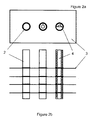
- the heat exchanger 1 comprises a plurality of tubes 2 which are arranged to carry a flow of a first heat exchanging medium in the form of a refrigerant (e.g. such as R134A-R410, R22, R404A refrigerant that are particularly suited for refrigeration applications).
- the tubes 2 extend through, and are in thermal contact with, a plurality of stacked fins 3 which are in perpendicular alignment to the tubes 2.
- the configuration of the tubes 2 and fins 3 act to transfer heat from the refrigerant circulating through the pipes to a second medium to thereby cool the refrigerant.
- the second medium is air which absorbs the heat from the refrigerant thereby allowing it to cool, condense and turn into a liquid before being recycled to an expansion device and an evaporator unit of the refrigerator.
- a flow direction control insert 4 which is arranged to be located within each tube (as shown in partial hidden detail in the right most tube 2c) and operable to control flow direction of the first medium through the tube to thereby vary the effective path length of the tube.
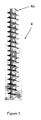
- the flow direction control inserts are in the form of helical screws 4 that effectively extend the length of each tube (and in turn improve the heat transfer characteristics as will be described in subsequent paragraphs).
- the screws are made of a deformable rubber and are sized such that outer circumference of each helical rib 4a is in direct contact with an inner surface of the tube to thereby form a flowpath (denoted in the drawings as a "gas channel") that serves to increase the effective length of the tube 2.
- a flowpath denoted in the drawings as a "gas channel”
- the ribs 4a of the helical screw 4 sealingly engage the tube's inner surface (i.e. an outer edge 5 of each rib 4a is arranged in an interference fit with an inner surface 6 of the tube), in other embodiments the ribs may not extend right the way thereto.
- the insert 4 may still serve to vary the effective path length, albeit not to the same extent as where they extend right the way.
- different helical screw configurations and dimensions will have an effect on the extent of the flow path variance.
- different capacity units will require different size chambers to allow correct flow.
- Different capacities may be achieved by means of increasing pipe and helical screw diameter and increasing/decreasing the inner diameter (shank) of the helical screw.
- the helical screw pitch will also adjust the effective length of the flow path; the smaller the pitch of the screw, the longer the effective flow path of the chamber.
- the helical screw may not have a shank but instead be in the form of a spring made from flat rather than a round section.
- a conventional fin and tube heat exchanger is manufactured from a plurality of fins with holes punched evenly, the quantity of which is commensurate with the heat load for the design of the condensing unit. Loose fitting tubes are then inserted through the punched holes and expanded so that the tube is a tight fit in the punched holes (step 502).
- a flow direction control insert in the form of a helical screw is inserted into one or more of the tubes, depending on the heat transfer characteristics required (in the illustrated embodiment it will be noted that all tubes have been used) . Insertion may be achieved by utilising an insert formed of a product that will deform on insertion and reform once in place (e.g. elastomeric type material).
- An alternative method may be to insert a thin walled metal helical screw with a bore through the centre that will allow a (bullet) to be drawn through the tube expanding the screw to the inner surface of the tube. According to such an embodiment the ends of the tube would need to be sealed prior to soldering the elbows on (described later). To retrofit an existing heat exchanger, the elbows on one end of the heat exchanger would need to be removed, the helical screw inserted and the elbows replaced.
- the ends of the tubes then have elbows soldered to one another to form a continuous serpentine arrangement. This is best illustrated in Figure 6 .
- a fan (not shown) may be added to force air over the fins.
- a two door drink fridge condensing unit was used for the trial.
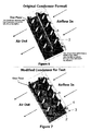
- the condenser tubing was split in two sections as can be seen from the Figure 7 schematic. Passes A to I (only some passes are shown in the schematic for illustrative purposes) were modified to accept the helical screw and used as the complete condensing unit, while passes J to U were kept standard (i.e. no flow direction control insert). Due to the halving of the capacity of the condenser, the trial was conducted in a low ambient temperature atmosphere. The results were then compared with the results using the passes J to U again in a low ambient temperature atmosphere. Whilst modifying the left hand part of the condenser some of the passes were damaged and could not be used.
- a conventional condenser unit from a Holden Astina (hereafter “the Astina condenser”) was set up on a test bench alongside a condenser incorporating a plurality of tubes including helical flow direction control inserts (hereafter “the helical screw condenser” ) , in accordance with an embodiment of the invention.
- the Astina condenser had a block size of 580 mm long x 300 high (i.e. effective fin area) and included a total of 28 tubes having 8 microchannels defined therein.
- the micro- channels measured 1.7 mm wide x 1.5 mm high.
- the helical screw condenser on the other hand measured only 490 mm long x 310 mm high.
- 10 tubes formed of 3/4" copper pipe were included in the screw condenser body.
- Each of the tubes incorporated helical screws of 17.6 mm O/D (outside diameter) 14.9 pitch (i.e. which in this case is the distance in millimeters between the leading edge of each turn of the helical thread), 1 mm blade thickness and centre stem diameter of 2.5 mm.
- a schematic of the tubing configuration of the helical screw condenser is shown in Figure 9 , where the screw body is designated by the reference numeral 10, the thread is designated by the reference numeral 12 and the fins are designated by reference numeral 14.
- the volume of gas through the helical screw condenser body 10 was measured as twice that of the volume through the Astina condenser. From the demonstration it was calculated that a pass of 13.9 mm in the micro channel condenser equated to approximately 57 mm in the new condenser, which increases the effective path length of the helical screw condenser by a factor of 4. Thus, for the same physical size of heat exchanger, the length of the new condenser would be 4 times longer at twice the volume (thereby, by calculation, making the new condenser 8 times bigger in capacity for the same physical size).
- the helical insert and outer tubing may be formed as one piece (i.e. integrally formed).
- the heat exchanger may be formed by extruding a length of heat transmissive material, such as aluminium, through a die so as to form a tube having an inner surface in which the flow direction control insert is formed.
- the outer fin(s) may be extruded with the tubing to minimise construction costs.
- the heat exchanger tubes may each comprise a primary flow path 15 arranged to carry the flow of the first heat exchanging medium and which surrounds a secondary flow path 16 which carries a second heat exchanging medium.
- a configuration advantageously allows heat from the first heat exchanging medium to not only be exchanged with air (or another suitable medium) passing over the outer wall 18 of the primary flow path 15, but in addition to exchange heat with a medium flowing through the enveloped secondary flow path 16.
- air or another suitable medium
- at least one of the primary and secondary flow paths may be helical for increasing their effective path length. Another advantage arising from the aforementioned tubular construction is that condensation is unable to pool on the primary flow path surface.
- a single heat exchanger tube 17 formed of a suitable heat transmissive material comprises an outer circumferential wall 18 which is surrounded by one or more heat exchanging fins 14 in the same manner as previously described with reference to Figure 9 .
- the secondary heat exchanging medium is carried within a separate inner tube 16a located within the tube body, while the first medium is carried within a flow path defined in the outer wall 18.
- the primary flow path 15 is partitioned by way of internal webs 20 so as to create a plurality of separate helical flow paths which extend along the length of the tube 17. This may serve to increase the heat transfer capabilities, as well as increase the structural strength of the exchanger tube.
- the primary flow path(s) need not necessarily be helical and could instead, for example, deviate in a serpentine or other suitable non-linear path.
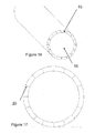
- the path(s) may be straight and non-deviating along the length of the tube as is shown in Figures 16 and 17 .
- the exchanger tube 17 (including its partitioned circumferential wall 18) may be formed by an extrusion process (i.e. in a linear fashion).
- the tube 17 may be formed by coiling/winding a straight length of tubing 19 of generally elongate cross section, such that the length extends along a helical path.
- Such a technique may advantageously allow manufacturers to utilise readily available straight flow tube lengths which are found in conventional heat exchanger designs (e.g. such as micro-channel tube lengths used in micro-channel heat exchangers) for forming the primary flow paths.
- Internal webs 20 formed within and extending along the length 19 may advantageously serve to direct the flow in a helical path along the tube (once coiled), for increasing the heat transfer characteristics.
- the tube length 19 is coiled or otherwise formed to create a closed outer circumferential wall which defines a sealed inner flow path for carrying the secondary flow (i.e. such that a separate inner tube is obviated).
- Figure 20 shows an alternative micro-channel design which could be formed into an exchanger tube as afore-described, whereby the fins 14 are integrally extruded with the channel.
- the exchanger tubes 17 are connected to an inlet and outlet manifold for receiving/expelling the respective heat exchanging mediums.
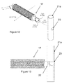
- Figure 12 shows an exploded view of the exchanger tube of Figure 11 , with an inlet manifold 21a in the form of a copper pipe.
- the outer wall 18 is paired away, exposing a length of the inner tube 16a which carries the secondary medium.
- the first end 19a is then inserted into an aperture 22 defined in a wall of the inlet manifold 21 such that the primary flow path is in fluid communication with the inlet manifold for delivering the first heat exchanging medium (in this case refrigerant gas).
- the first heat exchanging medium in this case refrigerant gas
- a portion of the inner tube 16a extends through a slightly smaller opposing aperture 23 in the inlet manifold wall, for receiving the secondary medium (in this case air, which may either be ambient air or alternatively air forced through the secondary flow path using a fan or the like).
- a second end 19b of the tube 17 is coupled to an outlet manifold 21b (which may, for example, be under vacuum) having the same form as the inlet manifold 21a in an identical manner.
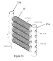
- An assembled view of a heat exchanger according to an embodiment is shown in Figure 14 .
- Figure 16 shows a sectional view of the manifold coupling through line A-A of Figure 15 .
- the number of flow paths defined in each tube of the exchanger may vary.
- the number of flow paths may reduce for each pass so as to account for changes in the state of the primary heat exchanging medium (e.g. liquid to gas or vice versa).
- the heat exchanging medium passing through the primary and secondary flow paths may be any suitable medium and should not be seen as being restricted to those described above.
- the secondary flow path carrying air it could instead carry water such that the primary heat exchanging medium is exchanging heat with two different mediums (i.e. air through the fins and water through the secondary flow path).
Landscapes
- Engineering & Computer Science (AREA)
- Physics & Mathematics (AREA)
- Thermal Sciences (AREA)
- Mechanical Engineering (AREA)
- General Engineering & Computer Science (AREA)
- Geometry (AREA)
- Heat-Exchange Devices With Radiators And Conduit Assemblies (AREA)
Applications Claiming Priority (1)
| Application Number | Priority Date | Filing Date | Title |
|---|---|---|---|
| AU2011902904A AU2011902904A0 (en) | 2011-07-19 | Heat Exchanger |
Publications (1)
| Publication Number | Publication Date |
|---|---|
| EP2549219A1 true EP2549219A1 (fr) | 2013-01-23 |
Family
ID=45812337
Family Applications (1)
| Application Number | Title | Priority Date | Filing Date |
|---|---|---|---|
| EP12275107A Withdrawn EP2549219A1 (fr) | 2011-07-19 | 2012-07-17 | Échangeur de chaleur |
Country Status (3)
| Country | Link |
|---|---|
| EP (1) | EP2549219A1 (fr) |
| AU (2) | AU2012200524B2 (fr) |
| NZ (1) | NZ598010A (fr) |
Cited By (4)
| Publication number | Priority date | Publication date | Assignee | Title |
|---|---|---|---|---|
| DE102014207660A1 (de) * | 2014-04-23 | 2015-10-29 | Mahle International Gmbh | Innerer Wärmeübertrager |
| WO2016012664A1 (fr) * | 2014-07-25 | 2016-01-28 | Hutchinson | Echangeur thermique tel qu'un echangeur interne pour circuit de climatisation de vehicule automobile et circuit l'incorporant |
| CN108286845A (zh) * | 2018-03-04 | 2018-07-17 | 青岛三友制冰设备有限公司 | 制冰用单板蒸发器及其运作方法 |
| CN109595970A (zh) * | 2018-12-28 | 2019-04-09 | 滨州中科催化技术有限公司 | 螺旋折流板及换热器 |
Families Citing this family (1)
| Publication number | Priority date | Publication date | Assignee | Title |
|---|---|---|---|---|
| AU2012200524B2 (en) * | 2009-07-06 | 2014-01-16 | Frederick Mark Webb | Heat Exchanger |
Citations (6)
| Publication number | Priority date | Publication date | Assignee | Title |
|---|---|---|---|---|
| US3151672A (en) * | 1961-10-30 | 1964-10-06 | Westinghouse Air Brake Co | Water cooled air cooler |
| US3197975A (en) * | 1962-08-24 | 1965-08-03 | Dunham Bush Inc | Refrigeration system and heat exchangers |
| JP2003139478A (ja) * | 2001-11-01 | 2003-05-14 | Ee R C:Kk | 熱交換器 |
| US20050236145A1 (en) * | 2004-04-27 | 2005-10-27 | Honda Motor Co., Ltd. | Heat exchanger |
| WO2011003140A1 (fr) * | 2009-07-06 | 2011-01-13 | Frederick Mark Webb | Échangeur thermique |
| US20120160465A1 (en) * | 2009-07-06 | 2012-06-28 | Webb Frederick Mark | Heat exchanger |
Family Cites Families (3)
| Publication number | Priority date | Publication date | Assignee | Title |
|---|---|---|---|---|
| FR1169790A (fr) * | 1957-03-18 | 1959-01-06 | Tubes d'échangeur de chaleur | |
| US4326582A (en) * | 1979-09-24 | 1982-04-27 | Rockwell International Corporation | Single element tube row heat exchanger |
| AU2012200524B2 (en) * | 2009-07-06 | 2014-01-16 | Frederick Mark Webb | Heat Exchanger |
-
2012
- 2012-01-31 AU AU2012200524A patent/AU2012200524B2/en active Active
- 2012-02-03 NZ NZ598010A patent/NZ598010A/xx unknown
- 2012-07-17 EP EP12275107A patent/EP2549219A1/fr not_active Withdrawn
-
2017
- 2017-07-18 AU AU2017206160A patent/AU2017206160B2/en active Active
Patent Citations (6)
| Publication number | Priority date | Publication date | Assignee | Title |
|---|---|---|---|---|
| US3151672A (en) * | 1961-10-30 | 1964-10-06 | Westinghouse Air Brake Co | Water cooled air cooler |
| US3197975A (en) * | 1962-08-24 | 1965-08-03 | Dunham Bush Inc | Refrigeration system and heat exchangers |
| JP2003139478A (ja) * | 2001-11-01 | 2003-05-14 | Ee R C:Kk | 熱交換器 |
| US20050236145A1 (en) * | 2004-04-27 | 2005-10-27 | Honda Motor Co., Ltd. | Heat exchanger |
| WO2011003140A1 (fr) * | 2009-07-06 | 2011-01-13 | Frederick Mark Webb | Échangeur thermique |
| US20120160465A1 (en) * | 2009-07-06 | 2012-06-28 | Webb Frederick Mark | Heat exchanger |
Cited By (6)
| Publication number | Priority date | Publication date | Assignee | Title |
|---|---|---|---|---|
| DE102014207660A1 (de) * | 2014-04-23 | 2015-10-29 | Mahle International Gmbh | Innerer Wärmeübertrager |
| WO2016012664A1 (fr) * | 2014-07-25 | 2016-01-28 | Hutchinson | Echangeur thermique tel qu'un echangeur interne pour circuit de climatisation de vehicule automobile et circuit l'incorporant |
| CN106574824A (zh) * | 2014-07-25 | 2017-04-19 | 哈金森公司 | 诸如内部交换器的用于机动车空调系统的热交换器和包括该热交换器的系统 |
| CN106574824B (zh) * | 2014-07-25 | 2019-05-17 | 哈金森公司 | 诸如内部交换器的用于机动车空调系统的热交换器和包括该热交换器的系统 |
| CN108286845A (zh) * | 2018-03-04 | 2018-07-17 | 青岛三友制冰设备有限公司 | 制冰用单板蒸发器及其运作方法 |
| CN109595970A (zh) * | 2018-12-28 | 2019-04-09 | 滨州中科催化技术有限公司 | 螺旋折流板及换热器 |
Also Published As
| Publication number | Publication date |
|---|---|
| AU2012200524A1 (en) | 2012-02-23 |
| AU2017206160B2 (en) | 2021-05-20 |
| AU2012200524B2 (en) | 2014-01-16 |
| NZ598010A (en) | 2013-08-30 |
| AU2017206160A1 (en) | 2019-02-07 |
Similar Documents
| Publication | Publication Date | Title |
|---|---|---|
| US10132570B2 (en) | Heat exchanger with multiple flow tubes for fluid circulation | |
| AU2017206160B2 (en) | Heat Exchanger | |
| KR101536552B1 (ko) | 열교환기용 파이프의 난류 발생 장치 | |
| CN108955327B (zh) | 用于冷却电子设备外壳的热交换器 | |
| US20110030932A1 (en) | Multichannel heat exchanger fins | |
| US20040188076A1 (en) | Heat exchanger | |
| CN218065155U (zh) | 换热器和换热系统 | |
| WO2011003140A1 (fr) | Échangeur thermique | |
| CN102692101A (zh) | 换热器及空调设备 | |
| US20060108107A1 (en) | Wound layered tube heat exchanger | |
| EP1971815B1 (fr) | Echangeur thermique a tube multicouche enroule en spirale | |
| US9733024B2 (en) | Tubing element with fins for a heat exchanger | |
| US20130098586A9 (en) | Wound Layered Tube Heat Exchanger | |
| KR20150030201A (ko) | 핀·앤드·튜브형 열 교환기용 전열관 및 그것을 사용한 핀·앤드·튜브형 열 교환기 | |
| JP2002228387A (ja) | 熱交換器 | |
| EP3126767B1 (fr) | Serpentins spiralés | |
| EP2941610B1 (fr) | Élément de tubage pour supports d'échangeur de chaleur | |
| CN116972454A (zh) | 一种换热系统 | |
| CN204880868U (zh) | 一种换热器及具有该换热器的空调系统 | |
| KR200314025Y1 (ko) | 핀튜브형 열교환기 및 이를 이용한 에어컨 및 냉동기 | |
| US20240280327A1 (en) | Heat exchanger | |
| CN106152613A (zh) | 一种换热器及具有该换热器的空调系统 | |
| KR200408236Y1 (ko) | 김치저장고용 응축기 | |
| KR100574869B1 (ko) | 액-기체 열 교환기 | |
| WO2014083553A1 (fr) | Élément de tubulure pour moyens formant échangeur de chaleur |
Legal Events
| Date | Code | Title | Description |
|---|---|---|---|
| PUAI | Public reference made under article 153(3) epc to a published international application that has entered the european phase |
Free format text: ORIGINAL CODE: 0009012 |
|
| AK | Designated contracting states |
Kind code of ref document: A1 Designated state(s): AL AT BE BG CH CY CZ DE DK EE ES FI FR GB GR HR HU IE IS IT LI LT LU LV MC MK MT NL NO PL PT RO RS SE SI SK SM TR |
|
| AX | Request for extension of the european patent |
Extension state: BA ME |
|
| 17P | Request for examination filed |
Effective date: 20130719 |
|
| RBV | Designated contracting states (corrected) |
Designated state(s): AL AT BE BG CH CY CZ DE DK EE ES FI FR GB GR HR HU IE IS IT LI LT LU LV MC MK MT NL NO PL PT RO RS SE SI SK SM TR |
|
| 17Q | First examination report despatched |
Effective date: 20140321 |
|
| STAA | Information on the status of an ep patent application or granted ep patent |
Free format text: STATUS: THE APPLICATION IS DEEMED TO BE WITHDRAWN |
|
| 18D | Application deemed to be withdrawn |
Effective date: 20150806 |