EP2549253B1 - Corps de mesure, capteur de mesure de force et agencement de mesure destinés à la mesure de forces - Google Patents
Corps de mesure, capteur de mesure de force et agencement de mesure destinés à la mesure de forces Download PDFInfo
- Publication number
- EP2549253B1 EP2549253B1 EP12158446.0A EP12158446A EP2549253B1 EP 2549253 B1 EP2549253 B1 EP 2549253B1 EP 12158446 A EP12158446 A EP 12158446A EP 2549253 B1 EP2549253 B1 EP 2549253B1
- Authority
- EP
- European Patent Office
- Prior art keywords
- measuring
- web
- force
- individual sensors
- longitudinal axis
- Prior art date
- Legal status (The legal status is an assumption and is not a legal conclusion. Google has not performed a legal analysis and makes no representation as to the accuracy of the status listed.)
- Active
Links
- 239000002655 kraft paper Substances 0.000 description 20
- 238000005259 measurement Methods 0.000 description 14
- 238000011156 evaluation Methods 0.000 description 4
- 230000005484 gravity Effects 0.000 description 4
- 238000000034 method Methods 0.000 description 3
- 230000002349 favourable effect Effects 0.000 description 2
- 238000003754 machining Methods 0.000 description 2
- 238000003801 milling Methods 0.000 description 2
- 238000012986 modification Methods 0.000 description 2
- 230000004048 modification Effects 0.000 description 2
- 239000007787 solid Substances 0.000 description 2
- 239000000758 substrate Substances 0.000 description 2
- 238000010276 construction Methods 0.000 description 1
- 230000001419 dependent effect Effects 0.000 description 1
- 238000011161 development Methods 0.000 description 1
- 230000018109 developmental process Effects 0.000 description 1
- 239000000835 fiber Substances 0.000 description 1
- 238000009434 installation Methods 0.000 description 1
- 238000004519 manufacturing process Methods 0.000 description 1
- 239000000463 material Substances 0.000 description 1
- 239000002184 metal Substances 0.000 description 1
- NJPPVKZQTLUDBO-UHFFFAOYSA-N novaluron Chemical group C1=C(Cl)C(OC(F)(F)C(OC(F)(F)F)F)=CC=C1NC(=O)NC(=O)C1=C(F)C=CC=C1F NJPPVKZQTLUDBO-UHFFFAOYSA-N 0.000 description 1
- 230000003287 optical effect Effects 0.000 description 1
Images




Classifications
-
- G—PHYSICS
- G01—MEASURING; TESTING
- G01L—MEASURING FORCE, STRESS, TORQUE, WORK, MECHANICAL POWER, MECHANICAL EFFICIENCY, OR FLUID PRESSURE
- G01L1/00—Measuring force or stress, in general
- G01L1/20—Measuring force or stress, in general by measuring variations in ohmic resistance of solid materials or of electrically-conductive fluids; by making use of electrokinetic cells, i.e. liquid-containing cells wherein an electrical potential is produced or varied upon the application of stress
- G01L1/22—Measuring force or stress, in general by measuring variations in ohmic resistance of solid materials or of electrically-conductive fluids; by making use of electrokinetic cells, i.e. liquid-containing cells wherein an electrical potential is produced or varied upon the application of stress using resistance strain gauges
- G01L1/2206—Special supports with preselected places to mount the resistance strain gauges; Mounting of supports
- G01L1/2243—Special supports with preselected places to mount the resistance strain gauges; Mounting of supports the supports being parallelogram-shaped
-
- G—PHYSICS
- G01—MEASURING; TESTING
- G01L—MEASURING FORCE, STRESS, TORQUE, WORK, MECHANICAL POWER, MECHANICAL EFFICIENCY, OR FLUID PRESSURE
- G01L5/00—Apparatus for, or methods of, measuring force, work, mechanical power, or torque, specially adapted for specific purposes
- G01L5/16—Apparatus for, or methods of, measuring force, work, mechanical power, or torque, specially adapted for specific purposes for measuring several components of force
- G01L5/161—Apparatus for, or methods of, measuring force, work, mechanical power, or torque, specially adapted for specific purposes for measuring several components of force using variations in ohmic resistance
- G01L5/1627—Apparatus for, or methods of, measuring force, work, mechanical power, or torque, specially adapted for specific purposes for measuring several components of force using variations in ohmic resistance of strain gauges
Definitions
- the invention relates to a measuring body for measuring forces, comprising two spaced-apart base parts, each having at least one mounting surface for introducing the forces to be measured, four identical, spaced, aligned along a longitudinal axis and arranged in a square webs, which with the two base parts are connected to spaced in the longitudinal axis connecting surfaces, as well as force sensors on each of said webs. Furthermore, the invention relates to a force measuring sensor and a measuring arrangement for measuring forces, in particular in connection with the aforementioned measuring body.
- measuring bodies The measurement of forces by means of the deformation of measuring bodies is known in principle.
- the CN 2156494 Y to a measuring body which in a section comprises four spaced, aligned along a longitudinal axis webs, where force sensors are mounted. With these forces can be determined normal to the said longitudinal axis.
- the from CN 2156494 Y Known measuring body in a further section two additional webs with force sensors. Further examples of measuring body are approximately from the DE 37 01 372 A1 and the US 3,696,317 A known.
- a disadvantage of the in the CN 2156494 Y disclosed measuring body is that it is constructed relatively complicated and volume is relatively large.
- a measuring body which has four webs between two base surfaces, wherein the webs are welded to the base surfaces. Strain gauges are distributed on the bars individually.
- the object of the invention is to provide an improved measuring body, an improved force measuring sensor and an improved measuring arrangement.
- a three-dimensional force measurement should be made possible with a simplified construction.
- the object of the invention is achieved with a measuring body of the type mentioned, with features according to claim 1.
- the necessary measuring body is relatively simple and requires only small volume.
- force measuring sensor is understood to mean that it is a sensor, via which ultimately the force can be determined. In most cases it is not the force that is measured directly, but rather an elongation.
- a "force measuring sensor” in the context of the invention forms a group of individual sensors for measuring a force or strain in only one direction.
- arranged in a square means that the center of gravity of the web cross sections lie in the middle of the side edges of a square, the cross sections of two adjacent webs are rotated by 90 ° relative to one another and the total cross section of the webs is symmetrical about the main axes of said square ,
- the "longitudinal axis of the webs" passes through the center of gravity of the said square and is aligned normal to this.
- the “measuring plane” is the plane in which the force measuring sensors mounted on a web are arranged.
- a favorable variant of a measuring body results when the force measuring sensors are identical at each of the webs. In this way, symmetrical conditions arise in the signals received from the force sensors, whereby the evaluation of the same is simplified.
- the individual sensors are designed as strain gauges. In this way, the measuring body, the force measuring sensor or the measuring arrangement can be easily put into practice, as is used on readily available and reliable measuring sensors.
- the base parts of the measuring body are identical, in particular with mutually parallel mounting surfaces.
- the measuring body can be used in two different layers with otherwise the same function. Errors when installing a measuring body in a component to be measured can thus be avoided.
- the webs are designed as prisms oriented parallel to the longitudinal axis and have a rectangular cross-section.
- the webs can be easily made. It is particularly advantageous if the measuring body is designed to be point-symmetrical. Because of the high degree of symmetry, the force measurement or the evaluation of the measurement signals using such a measuring body is particularly simple.
- the measuring body is integrally formed. In this way, substantially constant material properties in the measuring body and thus high measuring accuracy can be ensured.
- the width of a web is less than the distance between its two adjacent webs. This ensures that the bars can move freely. Furthermore, as an access for a milling tool can be made available when the measuring body is milled, for example, from the solid.
- Fig. 1 shows a first example of a measuring body 1a for measuring forces, comprising two spaced apart base parts 2a, 2b, each with at least one mounting surface for introducing the forces to be measured and four identical, spaced, aligned along a longitudinal axis z and arranged in a square webs A..D, which connect the two base parts 2a, 2b at spaced apart in the longitudinal axis connecting surfaces. On each of said webs A..D force measuring sensors 3A..3D are arranged.
- the measuring body 1a does not otherwise include any other force sensors.
- the base parts 2a, 2b are identical and have mutually parallel mounting surfaces, in which a plurality of mounting holes is provided.
- the webs A..D of the measuring body 1a are formed in this example as parallel to the longitudinal axis z aligned prisms, which have rectangular cross-section.
- the measuring body 1a may be integrally formed and milled, for example, made of solid metal.
- Fig. 2 shows another example of a measuring body 1b, which is very similar to the measuring body 1a. In contrast, but in the interior of the measuring body 1b to see podestetti parts that are remnants of a not completely milled interior.
- the machining process for the production of the measuring body 1b is significantly shortened by this procedure and the service life of the machining tool is extended.
- the width b of a web A..D of the measuring body 1b is less than the distance a of its two adjacent webs A..D.
- Fig. 3 finally shows a third example of a measuring body 1c in plan and elevation, which is also constructed similar to the measuring body 1a and 1b.
- the measuring body 1c but no prismatic webs, but in the middle tapered webs A '.. D', but also in each sectional plane have a rectangular cross-section.
- the webs A '.. D' are arranged "in square". This means that the center of gravity S of the web cross sections in the middle of the side edges of a square Q (in the Fig. 3 shown dotted) lie.
- the cross sections of two adjacent webs A '.. D' are rotated by 90 ° from each other, and the total cross section of the webs A '.. D' is symmetrical about the major axes of said square Q.
- the longitudinal axis z of the measuring body 1c and the webs A '.. D' passes through the center of gravity of said square Q and is normal to this aligned.
- the webs A..D of the measuring body 1a, 1b are arranged "square".
- the measuring body 1a..1c also have another special property. These are namely point-symmetrical about a point P formed.
- a voltage source in one diagonal and a voltmeter in the other diagonal is connected to the measuring bridge.
- the evaluation of the signal obtained from the measuring bridge can be done in a conventional manner and is therefore not explained in detail.
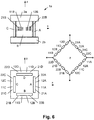
- FIGS. 6 to 8 the arrangement of the single sensors 11, 12, 21, 22, 31..34 was used, as they are in the Fig. 5 is shown. But this is not necessary.
- an arrangement according to Fig. 4 be used.
- the measuring bridge after Fig. 6 are then instead of the sensors 31 and 33, only the sensor 31 and instead of the sensors 32 and 34, only the sensor 32 to use.
- the procedure is analogous if several sensors are provided instead of a single sensor. If, for example, the sensor 11 is formed by a plurality of individual sensors, a series circuit of the individual sensors is to be inserted in the respective measuring bridges, etc.
- the illustrated examples are advantageous embodiments of the invention, modifications of the disclosed principle are possible.
- the basic parts 2a, 2b and their mounting surfaces can be adapted to the respective installation situation without changing the measuring principle. So you do not have to be identical.
- the measurement levels are not necessarily at the position shown or in the position shown. It would also be conceivable, for example, that the measurement plane is located on the inside of the webs A..D, A '.. D' or on their side surfaces.
- the individual sensors 3a, 3b, 3A..3D, 11, 12, 21, 22, 31..34 are designed as strain gauges. It would also be conceivable, for example, to use piezo sensors, magnetic or optical sensors, etc. The latter include, for example, fiber Bragg gratings.
- the measuring body 1a..1c is point symmetrical about a point P, although this is advantageous for reasons of symmetry.
Landscapes
- Physics & Mathematics (AREA)
- General Physics & Mathematics (AREA)
- Force Measurement Appropriate To Specific Purposes (AREA)
Claims (10)
- Corps de mesure (1a .. 1c) pour la mesure de forces, comprenant- deux pièces de base (2a, 2b) espacées l'une de l'autre, avec chacune au moins une face de montage pour l'introduction des forces à mesurer,- quatre ailes identiques (A .. D, A' .. D'), espacées l'une de l'autre, orientées le long d'un axe longitudinal (z) et agencées en un carré (Q), qui sont assemblées aux deux pièces de base (2a, 2b) par des faces d'assemblage espacées selon l'axe longitudinal,caractérisé en ce que le corps de mesure (1a .. 1c) est réalisé en une seule pièce, dans lequel les ailes (A .. D) sont réalisées en forme de prismes orientés parallèlement à l'axe longitudinal (z), dans lequel les prismes/ailes (A .. D) ont une section transversale rectangulaire, et dans lequel le corps de mesure (1a .. 1c) comprend des capteurs de mesure de force (3a, 3b, 3A .. 3D) sur chacune desdites ailes (A .. D, A' .. D'), dans lequel les capteurs de mesure de force (3a, 3b, 3A .. 3D) sont formés sur chacune desdites ailes (A ..D, A' .. D') respectivement par un groupe de capteurs individuels (11, 12, 21, 22, 31 .. 34), dans lequel les capteurs individuels (11, 12, 21, 22, 31 .. 34) mesurent respectivement une force dans une direction et en ce que le corps de mesure (1a .. 1c) ne comprend que de tels capteurs de mesure de force (3a, 3b, 3A .. 3D).
- Corps de mesure (1a .. 1c) selon la revendication 1, caractérisé en ce que les capteurs de mesure de force (3a, 3b, 3A .. 3D) sont identiques sur chacune des ailes (A .. D, A' .. D').
- Corps de mesure (1a .. 1c) selon la revendication 2, caractérisé en ce que chaque aile (A .. D, A' .. D') présente un plan de mesure, qui est orienté parallèlement à l'axe longitudinal (z) des ailes (A .. D, A' .. D'), et en ce qu'il est prévu dans chaque plan de mesure un agencement identique et symétrique de capteurs individuels (11, 12, 21, 22, 31 .. 34), comprenant respectivement- chaque fois deux premiers capteurs individuels (11, 12) pour la mesure d'une force dans ledit axe longitudinal (z),- chaque fois deux deuxièmes capteurs individuels (21, 22) pour la mesure d'une force normalement audit axe longitudinal (z),- chaque fois au moins un troisième capteur individuel (31, 33) pour la mesure d'une force sous un angle de +45° par rapport audit axe longitudinal (z), et- chaque fois au moins un quatrième capteur individuel (32, 34) pour la mesure d'une force sous un angle de -45° par rapport audit axe longitudinal (z).
- Corps de mesure (1a .. 1c) selon la revendication 3, caractérisé par- chaque fois deux troisièmes capteurs individuels (31, 33) pour la mesure d'une force sous un angle de +45° par rapport audit axe longitudinal (z), et- chaque fois deux quatrièmes capteurs individuels (32, 34) pour la mesure d'une force sous un angle de -45 ° par rapport audit axe longitudinal (z).
- Corps de mesure (1a .. 1c) selon l'une quelconque des revendications 1 à 4, caractérisé en ce que les capteurs individuels (11, 12, 21, 22, 31 .. 34) sont réalisés en forme de jauges extensométriques.
- Corps de mesure (1a .. 1c) selon l'une quelconque des revendications précédentes, caractérisé en ce que les pièces de base (2a, 2b) sont identiques.
- Corps de mesure (1a .. 1c) selon l'une quelconque des revendications précédentes, caractérisé en ce qu'il est formé avec la symétrie ponctuelle autour d'un point (P).
- Corps de mesure (1a .. 1c) selon la revendication 1, caractérisé en ce que la largeur (b) d'une aile (A .. D, A' .. D') est plus petite que la distance (a) de ses deux ailes voisines (A .. D, A' .. D').
- Agencement de mesure avec un corps de mesure (1a .. 1c) selon l'une quelconque des revendications 3 à 8, caractérisé en ce que sont disposés dans les quatre branches d'un pont de mesure de Wheatstone pour la mesure d'une force selon l'axe longitudinal (z) avec le sens de la direction constant:- dans une première branche les premiers capteurs individuels (11A, 12A) d'une première aile (A) et les premiers capteurs individuels (11C, 12C) d'une troisième aile opposée (C),- dans une deuxième branche les deuxièmes capteurs individuels (21B, 22B) d'une deuxième aile (B) voisine de la première aile (A) et les deuxièmes capteurs individuels (21D, 22D) d'une quatrième aile (D) opposée à la deuxième aile (B),- dans une troisième branche les premiers capteurs individuels (11B, 12B) de la deuxième aile (B) et les premiers capteurs individuels (11D, 12D) de la quatrième aile (D), et- dans une quatrième branche les deuxièmes capteurs individuels (21A, 22A) de la première aile (A) et les deuxièmes capteurs individuels (21C, 22C) de la troisième aile (C).
- Agencement de mesure avec un corps de mesure (1a .. 1c) selon l'une quelconque des revendications 3 à 8, caractérisé en ce que sont disposés dans les quatre branches d'un pont de mesure de Wheatstone pour la mesure d'une force normalement au plan de mesure d'une première aile (A) avec un sens de la direction constant:- dans une première branche les troisièmes capteurs individuels (31B, 33B) d'une deuxième aile (B) voisine de la première aile (A),- dans une deuxième branche les quatrièmes capteurs individuels (32B, 34B) de la deuxième aile (B),- dans une troisième branche les quatrièmes capteurs individuels (32D, 34D) d'une quatrième aile (D) opposée à la deuxième aile (B), et- dans une quatrième branche les troisièmes capteurs individuels (31D, 33D) de la quatrième aile (D).
Priority Applications (3)
| Application Number | Priority Date | Filing Date | Title |
|---|---|---|---|
| EP17174538.3A EP3239676A1 (fr) | 2011-07-19 | 2012-03-07 | Capteur dynamométrique |
| CN201210236671.9A CN102889953B (zh) | 2011-07-19 | 2012-07-09 | 用于测力的测量元件、测力传感器及测量组件 |
| US13/552,674 US9127997B2 (en) | 2011-07-19 | 2012-07-19 | Measuring element, force-measuring sensor, and measuring assembly for measuring forces |
Applications Claiming Priority (1)
| Application Number | Priority Date | Filing Date | Title |
|---|---|---|---|
| US201161509185P | 2011-07-19 | 2011-07-19 |
Related Child Applications (2)
| Application Number | Title | Priority Date | Filing Date |
|---|---|---|---|
| EP17174538.3A Division EP3239676A1 (fr) | 2011-07-19 | 2012-03-07 | Capteur dynamométrique |
| EP17174538.3A Division-Into EP3239676A1 (fr) | 2011-07-19 | 2012-03-07 | Capteur dynamométrique |
Publications (2)
| Publication Number | Publication Date |
|---|---|
| EP2549253A1 EP2549253A1 (fr) | 2013-01-23 |
| EP2549253B1 true EP2549253B1 (fr) | 2017-08-09 |
Family
ID=45841276
Family Applications (2)
| Application Number | Title | Priority Date | Filing Date |
|---|---|---|---|
| EP12158446.0A Active EP2549253B1 (fr) | 2011-07-19 | 2012-03-07 | Corps de mesure, capteur de mesure de force et agencement de mesure destinés à la mesure de forces |
| EP17174538.3A Withdrawn EP3239676A1 (fr) | 2011-07-19 | 2012-03-07 | Capteur dynamométrique |
Family Applications After (1)
| Application Number | Title | Priority Date | Filing Date |
|---|---|---|---|
| EP17174538.3A Withdrawn EP3239676A1 (fr) | 2011-07-19 | 2012-03-07 | Capteur dynamométrique |
Country Status (3)
| Country | Link |
|---|---|
| US (1) | US9127997B2 (fr) |
| EP (2) | EP2549253B1 (fr) |
| CN (1) | CN102889953B (fr) |
Families Citing this family (24)
| Publication number | Priority date | Publication date | Assignee | Title |
|---|---|---|---|---|
| CN102589765B (zh) * | 2012-03-19 | 2014-07-23 | 南宁宇立汽车安全技术研发有限公司 | 多维力传感器 |
| US8943902B2 (en) * | 2012-10-05 | 2015-02-03 | Harris Corporation | Force and torque sensors |
| CN103115716A (zh) * | 2013-01-25 | 2013-05-22 | 南京理工大学 | 六分量试验台推力墩装置 |
| DE102013202647A1 (de) * | 2013-02-19 | 2014-08-21 | Airbus Operations Gmbh | Vorrichtung und Verfahren zur Messung von Schnittkräften |
| CN103616121B (zh) * | 2013-10-25 | 2016-04-13 | 浙江工业大学 | 三维风压测试仪 |
| KR101542977B1 (ko) * | 2013-12-27 | 2015-08-12 | 현대자동차 주식회사 | 스위칭 타입 육축 힘 토크 센서 및 이를 이용한 육축 힘 토크 측정장치 |
| WO2015145313A1 (fr) * | 2014-03-28 | 2015-10-01 | Consiglio Nazionale Delle Ricerche | Transducteur de forces radiales, en particulier pour des arbres rotatifs |
| JP6684828B2 (ja) * | 2015-05-08 | 2020-04-22 | エムティーエス システムズ コーポレイション | 多軸ロードセル本体 |
| DE102015108030B3 (de) * | 2015-05-21 | 2016-08-04 | Werner Stehr Tribologie | Drehmomentmessvorrichtung zur Messung von Reibkräften |
| FR3037396B1 (fr) | 2015-06-12 | 2017-06-23 | Lyon Ecole Centrale | Dispositif de mesure d'efforts a precision elevee |
| DE102015215099B3 (de) * | 2015-08-07 | 2016-12-08 | Dr. Doll Holding Gmbh | Kraft-Moment-Sensor sowie Dehnmessstreifen-System und Platinenanordnung für einen derartigen Kraft-Moment-Sensor |
| GB2558871B (en) * | 2016-10-28 | 2021-01-06 | Datum Electronics Ltd | Strain gauge |
| TWI628423B (zh) * | 2017-02-09 | 2018-07-01 | 國立中山大學 | 測力裝置 |
| FR3064356B1 (fr) * | 2017-03-27 | 2019-06-07 | Centre Technique Des Industries Mecaniques Et Du Decolletage | Disposititf de mesure d'efforts de fraisage |
| EP3460437B1 (fr) * | 2017-09-25 | 2021-10-27 | ETA SA Manufacture Horlogère Suisse | Dispositif d'etalonnage dynamique de couple et/ou force |
| CN108132119B (zh) * | 2017-12-29 | 2025-02-07 | 盘天(厦门)智能交通有限公司 | 一种传感器 |
| CN108020369B (zh) * | 2017-12-29 | 2024-07-26 | 盘天(厦门)智能交通有限公司 | 一种称台及称台铺装结构 |
| CN108955969B (zh) * | 2018-08-31 | 2021-03-02 | 纳恩博(北京)科技有限公司 | 电阻应变片、感应组件、力传感器和滑板 |
| US12491057B2 (en) * | 2019-10-23 | 2025-12-09 | Solventum Intellectual Properties Company | Force sensor system |
| JP7618916B2 (ja) * | 2020-12-24 | 2025-01-22 | ミネベアミツミ株式会社 | 起歪体、力覚センサ装置 |
| CN112833770B (zh) * | 2021-02-26 | 2022-12-13 | 中航电测仪器股份有限公司 | 一种复式全桥应变计 |
| CN113514185A (zh) * | 2021-04-27 | 2021-10-19 | 中国重汽集团济南动力有限公司 | 一种发动机悬置三轴力传感器及其适配装置 |
| CA3208895A1 (fr) * | 2022-08-19 | 2024-02-19 | Orpyx Medical Technologies Inc. | Capteurs et systemes de capteurs pour mesurer une force de cisaillement et un couple vertical |
| DE102024128291B3 (de) | 2024-09-30 | 2025-10-30 | Sew-Eurodrive Gmbh & Co. Kg | System |
Citations (1)
| Publication number | Priority date | Publication date | Assignee | Title |
|---|---|---|---|---|
| DE19525231A1 (de) * | 1995-07-11 | 1997-01-23 | Hottinger Messtechnik Baldwin | Drehmomentsensor |
Family Cites Families (16)
| Publication number | Priority date | Publication date | Assignee | Title |
|---|---|---|---|---|
| US3618376A (en) * | 1969-12-19 | 1971-11-09 | Chrysler Corp | Multiaxial load cell |
| US3696317A (en) | 1970-08-19 | 1972-10-03 | Waukesha Bearings Corp | Low capacity, low profile load cell |
| US4065962A (en) * | 1974-10-29 | 1978-01-03 | Gse, Inc. | Load cell |
| US4094192A (en) * | 1976-09-20 | 1978-06-13 | The Charles Stark Draper Laboratory, Inc. | Method and apparatus for six degree of freedom force sensing |
| DE3701372A1 (de) | 1987-01-19 | 1988-07-28 | Bayerische Motoren Werke Ag | Flaechenfoermiger kraftaufnehmer |
| FR2623284B1 (fr) * | 1987-11-13 | 1990-08-10 | Logabex | Capteur d'efforts spatiaux |
| US4911024A (en) * | 1989-02-10 | 1990-03-27 | Barry Wright Corporation | Force sensing |
| DE8909048U1 (de) * | 1989-07-26 | 1989-10-05 | Dornier Gmbh, 7990 Friedrichshafen | Kraftmeßsensor |
| CN2156494Y (zh) | 1993-05-22 | 1994-02-16 | 中国广西对外经济文化交流中心 | 三维力传感器 |
| JP3131642B2 (ja) * | 1994-09-14 | 2001-02-05 | 日本電子工業株式会社 | 応力複合化センサ及びこれを用いた構造体の応力測定装置 |
| SE521848C2 (sv) * | 2002-04-02 | 2003-12-09 | Metso Paper Inc | Förfarande och anordning för mätning av kraftpåkänningar hos raffinörer |
| CN100478662C (zh) * | 2005-12-16 | 2009-04-15 | 中国科学院合肥物质科学研究院 | 三维指力传感器及其信息获取方法 |
| JP4697004B2 (ja) * | 2006-03-29 | 2011-06-08 | 株式会社日立製作所 | 力学量測定装置 |
| US20090007696A1 (en) * | 2007-07-05 | 2009-01-08 | Nitta Corporation | Strain gauge type sensor |
| US7726199B2 (en) * | 2008-04-08 | 2010-06-01 | Wisconsin Alumni Research Foundation | Dielectrostrictive sensor for measuring deformation |
| CN101419102B (zh) * | 2008-11-25 | 2010-09-15 | 中国科学院合肥物质科学研究院 | 超薄六维力传感器及其测量三维力和三维力矩信息的方法 |
-
2012
- 2012-03-07 EP EP12158446.0A patent/EP2549253B1/fr active Active
- 2012-03-07 EP EP17174538.3A patent/EP3239676A1/fr not_active Withdrawn
- 2012-07-09 CN CN201210236671.9A patent/CN102889953B/zh active Active
- 2012-07-19 US US13/552,674 patent/US9127997B2/en active Active
Patent Citations (1)
| Publication number | Priority date | Publication date | Assignee | Title |
|---|---|---|---|---|
| DE19525231A1 (de) * | 1995-07-11 | 1997-01-23 | Hottinger Messtechnik Baldwin | Drehmomentsensor |
Also Published As
| Publication number | Publication date |
|---|---|
| EP3239676A1 (fr) | 2017-11-01 |
| CN102889953B (zh) | 2015-10-28 |
| CN102889953A (zh) | 2013-01-23 |
| US9127997B2 (en) | 2015-09-08 |
| EP2549253A1 (fr) | 2013-01-23 |
| US20130061689A1 (en) | 2013-03-14 |
Similar Documents
| Publication | Publication Date | Title |
|---|---|---|
| EP2549253B1 (fr) | Corps de mesure, capteur de mesure de force et agencement de mesure destinés à la mesure de forces | |
| DE60126032T2 (de) | Inspektionseichblock und dessen produktion | |
| DE102016114193B4 (de) | Kraftmesseinrichtung zur mehrachsigen Erfassung einwirkender Kräfte und Momente | |
| DE102010047234B4 (de) | Wägemodul zur Messung von Radaufstandskräften | |
| DE102008041327A1 (de) | Dreiachsiger Beschleunigungssensor | |
| WO2015010684A1 (fr) | Capteur de force en forme de barre avec comportement de déformation amélioré | |
| DE68908144T2 (de) | Ausdehnungsmesssonde zur Messung der Belastung für ein Bohrelement. | |
| WO2015010683A1 (fr) | Dispositif d'absorption de force en forme de bâton à égalisation simplifiée | |
| DE102011007350B4 (de) | Sensor zur taktilen Messung von Kräften und Momenten | |
| DE102009000255B4 (de) | Messachse | |
| DE102004033925B4 (de) | Drehmoment-Messaufnehmer | |
| DE102010012701B4 (de) | Mikrokraftsensor | |
| DE2758997C2 (de) | Meßglied zum Messen des Raddruckes des Rades eines Schienenfahrzeuges | |
| DE102018001880A1 (de) | Sensorvorrichtung zur Messung von Relativbewegungen von zwei Bereichen einer Oberfläche | |
| DE3701372C2 (fr) | ||
| DE102011057169A1 (de) | Mikroelektromechanisches System | |
| DE102005033527B4 (de) | Vorrichtung zur Erfassung von Kräften und/oder Momenten | |
| EP3650825B1 (fr) | Mesure de la force operationnelle d'une composante mecanique | |
| DE102010029074B4 (de) | Anbindungsstruktur für Mikroschwingeneinrichtungen | |
| DE102007018422A1 (de) | Parallelogrammlenkerstruktur, insbesondere monolothische Parallelogrammlenkerstruktur für einen Wägeaufnehmer | |
| DE102007052201B3 (de) | Anordnung zur Überwachung der Funktion und des Zustands von Tragwerklagern an Bauwerken | |
| DE3513935C2 (de) | Meßfeder | |
| DE3100949C2 (de) | Vorrichtung zum Wägen von Transportfahrzeugen während der Fahrt | |
| EP2766704B1 (fr) | Capteur de couple et de force | |
| WO2008148772A1 (fr) | Élément et système de construction de dispositifs permettant de serrer des pièces |
Legal Events
| Date | Code | Title | Description |
|---|---|---|---|
| PUAI | Public reference made under article 153(3) epc to a published international application that has entered the european phase |
Free format text: ORIGINAL CODE: 0009012 |
|
| AK | Designated contracting states |
Kind code of ref document: A1 Designated state(s): AL AT BE BG CH CY CZ DE DK EE ES FI FR GB GR HR HU IE IS IT LI LT LU LV MC MK MT NL NO PL PT RO RS SE SI SK SM TR |
|
| AX | Request for extension of the european patent |
Extension state: BA ME |
|
| 17P | Request for examination filed |
Effective date: 20130723 |
|
| RBV | Designated contracting states (corrected) |
Designated state(s): AL AT BE BG CH CY CZ DE DK EE ES FI FR GB GR HR HU IE IS IT LI LT LU LV MC MK MT NL NO PL PT RO RS SE SI SK SM TR |
|
| 17Q | First examination report despatched |
Effective date: 20130926 |
|
| GRAP | Despatch of communication of intention to grant a patent |
Free format text: ORIGINAL CODE: EPIDOSNIGR1 |
|
| INTG | Intention to grant announced |
Effective date: 20170420 |
|
| GRAS | Grant fee paid |
Free format text: ORIGINAL CODE: EPIDOSNIGR3 |
|
| GRAA | (expected) grant |
Free format text: ORIGINAL CODE: 0009210 |
|
| AK | Designated contracting states |
Kind code of ref document: B1 Designated state(s): AL AT BE BG CH CY CZ DE DK EE ES FI FR GB GR HR HU IE IS IT LI LT LU LV MC MK MT NL NO PL PT RO RS SE SI SK SM TR |
|
| REG | Reference to a national code |
Ref country code: GB Ref legal event code: FG4D Free format text: NOT ENGLISH |
|
| REG | Reference to a national code |
Ref country code: CH Ref legal event code: EP Ref country code: AT Ref legal event code: REF Ref document number: 917359 Country of ref document: AT Kind code of ref document: T Effective date: 20170815 |
|
| REG | Reference to a national code |
Ref country code: IE Ref legal event code: FG4D Free format text: LANGUAGE OF EP DOCUMENT: GERMAN |
|
| REG | Reference to a national code |
Ref country code: DE Ref legal event code: R096 Ref document number: 502012010950 Country of ref document: DE |
|
| REG | Reference to a national code |
Ref country code: NL Ref legal event code: MP Effective date: 20170809 |
|
| REG | Reference to a national code |
Ref country code: LT Ref legal event code: MG4D |
|
| PG25 | Lapsed in a contracting state [announced via postgrant information from national office to epo] |
Ref country code: NO Free format text: LAPSE BECAUSE OF FAILURE TO SUBMIT A TRANSLATION OF THE DESCRIPTION OR TO PAY THE FEE WITHIN THE PRESCRIBED TIME-LIMIT Effective date: 20171109 Ref country code: HR Free format text: LAPSE BECAUSE OF FAILURE TO SUBMIT A TRANSLATION OF THE DESCRIPTION OR TO PAY THE FEE WITHIN THE PRESCRIBED TIME-LIMIT Effective date: 20170809 Ref country code: SE Free format text: LAPSE BECAUSE OF FAILURE TO SUBMIT A TRANSLATION OF THE DESCRIPTION OR TO PAY THE FEE WITHIN THE PRESCRIBED TIME-LIMIT Effective date: 20170809 Ref country code: LT Free format text: LAPSE BECAUSE OF FAILURE TO SUBMIT A TRANSLATION OF THE DESCRIPTION OR TO PAY THE FEE WITHIN THE PRESCRIBED TIME-LIMIT Effective date: 20170809 Ref country code: NL Free format text: LAPSE BECAUSE OF FAILURE TO SUBMIT A TRANSLATION OF THE DESCRIPTION OR TO PAY THE FEE WITHIN THE PRESCRIBED TIME-LIMIT Effective date: 20170809 Ref country code: FI Free format text: LAPSE BECAUSE OF FAILURE TO SUBMIT A TRANSLATION OF THE DESCRIPTION OR TO PAY THE FEE WITHIN THE PRESCRIBED TIME-LIMIT Effective date: 20170809 |
|
| PG25 | Lapsed in a contracting state [announced via postgrant information from national office to epo] |
Ref country code: PL Free format text: LAPSE BECAUSE OF FAILURE TO SUBMIT A TRANSLATION OF THE DESCRIPTION OR TO PAY THE FEE WITHIN THE PRESCRIBED TIME-LIMIT Effective date: 20170809 Ref country code: ES Free format text: LAPSE BECAUSE OF FAILURE TO SUBMIT A TRANSLATION OF THE DESCRIPTION OR TO PAY THE FEE WITHIN THE PRESCRIBED TIME-LIMIT Effective date: 20170809 Ref country code: BG Free format text: LAPSE BECAUSE OF FAILURE TO SUBMIT A TRANSLATION OF THE DESCRIPTION OR TO PAY THE FEE WITHIN THE PRESCRIBED TIME-LIMIT Effective date: 20171109 Ref country code: IS Free format text: LAPSE BECAUSE OF FAILURE TO SUBMIT A TRANSLATION OF THE DESCRIPTION OR TO PAY THE FEE WITHIN THE PRESCRIBED TIME-LIMIT Effective date: 20171209 Ref country code: LV Free format text: LAPSE BECAUSE OF FAILURE TO SUBMIT A TRANSLATION OF THE DESCRIPTION OR TO PAY THE FEE WITHIN THE PRESCRIBED TIME-LIMIT Effective date: 20170809 Ref country code: RS Free format text: LAPSE BECAUSE OF FAILURE TO SUBMIT A TRANSLATION OF THE DESCRIPTION OR TO PAY THE FEE WITHIN THE PRESCRIBED TIME-LIMIT Effective date: 20170809 Ref country code: GR Free format text: LAPSE BECAUSE OF FAILURE TO SUBMIT A TRANSLATION OF THE DESCRIPTION OR TO PAY THE FEE WITHIN THE PRESCRIBED TIME-LIMIT Effective date: 20171110 |
|
| REG | Reference to a national code |
Ref country code: FR Ref legal event code: PLFP Year of fee payment: 7 |
|
| PG25 | Lapsed in a contracting state [announced via postgrant information from national office to epo] |
Ref country code: RO Free format text: LAPSE BECAUSE OF FAILURE TO SUBMIT A TRANSLATION OF THE DESCRIPTION OR TO PAY THE FEE WITHIN THE PRESCRIBED TIME-LIMIT Effective date: 20170809 Ref country code: DK Free format text: LAPSE BECAUSE OF FAILURE TO SUBMIT A TRANSLATION OF THE DESCRIPTION OR TO PAY THE FEE WITHIN THE PRESCRIBED TIME-LIMIT Effective date: 20170809 Ref country code: CZ Free format text: LAPSE BECAUSE OF FAILURE TO SUBMIT A TRANSLATION OF THE DESCRIPTION OR TO PAY THE FEE WITHIN THE PRESCRIBED TIME-LIMIT Effective date: 20170809 |
|
| REG | Reference to a national code |
Ref country code: DE Ref legal event code: R097 Ref document number: 502012010950 Country of ref document: DE |
|
| PG25 | Lapsed in a contracting state [announced via postgrant information from national office to epo] |
Ref country code: SK Free format text: LAPSE BECAUSE OF FAILURE TO SUBMIT A TRANSLATION OF THE DESCRIPTION OR TO PAY THE FEE WITHIN THE PRESCRIBED TIME-LIMIT Effective date: 20170809 Ref country code: IT Free format text: LAPSE BECAUSE OF FAILURE TO SUBMIT A TRANSLATION OF THE DESCRIPTION OR TO PAY THE FEE WITHIN THE PRESCRIBED TIME-LIMIT Effective date: 20170809 Ref country code: EE Free format text: LAPSE BECAUSE OF FAILURE TO SUBMIT A TRANSLATION OF THE DESCRIPTION OR TO PAY THE FEE WITHIN THE PRESCRIBED TIME-LIMIT Effective date: 20170809 Ref country code: SM Free format text: LAPSE BECAUSE OF FAILURE TO SUBMIT A TRANSLATION OF THE DESCRIPTION OR TO PAY THE FEE WITHIN THE PRESCRIBED TIME-LIMIT Effective date: 20170809 |
|
| PLBE | No opposition filed within time limit |
Free format text: ORIGINAL CODE: 0009261 |
|
| STAA | Information on the status of an ep patent application or granted ep patent |
Free format text: STATUS: NO OPPOSITION FILED WITHIN TIME LIMIT |
|
| 26N | No opposition filed |
Effective date: 20180511 |
|
| PG25 | Lapsed in a contracting state [announced via postgrant information from national office to epo] |
Ref country code: SI Free format text: LAPSE BECAUSE OF FAILURE TO SUBMIT A TRANSLATION OF THE DESCRIPTION OR TO PAY THE FEE WITHIN THE PRESCRIBED TIME-LIMIT Effective date: 20170809 |
|
| PG25 | Lapsed in a contracting state [announced via postgrant information from national office to epo] |
Ref country code: MT Free format text: LAPSE BECAUSE OF FAILURE TO SUBMIT A TRANSLATION OF THE DESCRIPTION OR TO PAY THE FEE WITHIN THE PRESCRIBED TIME-LIMIT Effective date: 20170809 |
|
| REG | Reference to a national code |
Ref country code: CH Ref legal event code: PL |
|
| PG25 | Lapsed in a contracting state [announced via postgrant information from national office to epo] |
Ref country code: MC Free format text: LAPSE BECAUSE OF FAILURE TO SUBMIT A TRANSLATION OF THE DESCRIPTION OR TO PAY THE FEE WITHIN THE PRESCRIBED TIME-LIMIT Effective date: 20170809 |
|
| REG | Reference to a national code |
Ref country code: BE Ref legal event code: MM Effective date: 20180331 |
|
| REG | Reference to a national code |
Ref country code: IE Ref legal event code: MM4A |
|
| PG25 | Lapsed in a contracting state [announced via postgrant information from national office to epo] |
Ref country code: LU Free format text: LAPSE BECAUSE OF NON-PAYMENT OF DUE FEES Effective date: 20180307 |
|
| PG25 | Lapsed in a contracting state [announced via postgrant information from national office to epo] |
Ref country code: IE Free format text: LAPSE BECAUSE OF NON-PAYMENT OF DUE FEES Effective date: 20180307 |
|
| PG25 | Lapsed in a contracting state [announced via postgrant information from national office to epo] |
Ref country code: CH Free format text: LAPSE BECAUSE OF NON-PAYMENT OF DUE FEES Effective date: 20180331 Ref country code: BE Free format text: LAPSE BECAUSE OF NON-PAYMENT OF DUE FEES Effective date: 20180331 Ref country code: LI Free format text: LAPSE BECAUSE OF NON-PAYMENT OF DUE FEES Effective date: 20180331 |
|
| REG | Reference to a national code |
Ref country code: AT Ref legal event code: MM01 Ref document number: 917359 Country of ref document: AT Kind code of ref document: T Effective date: 20180307 |
|
| PG25 | Lapsed in a contracting state [announced via postgrant information from national office to epo] |
Ref country code: AT Free format text: LAPSE BECAUSE OF NON-PAYMENT OF DUE FEES Effective date: 20180307 |
|
| PG25 | Lapsed in a contracting state [announced via postgrant information from national office to epo] |
Ref country code: TR Free format text: LAPSE BECAUSE OF FAILURE TO SUBMIT A TRANSLATION OF THE DESCRIPTION OR TO PAY THE FEE WITHIN THE PRESCRIBED TIME-LIMIT Effective date: 20170809 |
|
| PGFP | Annual fee paid to national office [announced via postgrant information from national office to epo] |
Ref country code: GB Payment date: 20200323 Year of fee payment: 9 |
|
| PG25 | Lapsed in a contracting state [announced via postgrant information from national office to epo] |
Ref country code: HU Free format text: LAPSE BECAUSE OF FAILURE TO SUBMIT A TRANSLATION OF THE DESCRIPTION OR TO PAY THE FEE WITHIN THE PRESCRIBED TIME-LIMIT; INVALID AB INITIO Effective date: 20120307 Ref country code: PT Free format text: LAPSE BECAUSE OF FAILURE TO SUBMIT A TRANSLATION OF THE DESCRIPTION OR TO PAY THE FEE WITHIN THE PRESCRIBED TIME-LIMIT Effective date: 20170809 |
|
| PG25 | Lapsed in a contracting state [announced via postgrant information from national office to epo] |
Ref country code: CY Free format text: LAPSE BECAUSE OF FAILURE TO SUBMIT A TRANSLATION OF THE DESCRIPTION OR TO PAY THE FEE WITHIN THE PRESCRIBED TIME-LIMIT Effective date: 20170809 Ref country code: MK Free format text: LAPSE BECAUSE OF NON-PAYMENT OF DUE FEES Effective date: 20170809 |
|
| PGFP | Annual fee paid to national office [announced via postgrant information from national office to epo] |
Ref country code: FR Payment date: 20200320 Year of fee payment: 9 |
|
| PG25 | Lapsed in a contracting state [announced via postgrant information from national office to epo] |
Ref country code: AL Free format text: LAPSE BECAUSE OF FAILURE TO SUBMIT A TRANSLATION OF THE DESCRIPTION OR TO PAY THE FEE WITHIN THE PRESCRIBED TIME-LIMIT Effective date: 20170809 |
|
| GBPC | Gb: european patent ceased through non-payment of renewal fee |
Effective date: 20210307 |
|
| PG25 | Lapsed in a contracting state [announced via postgrant information from national office to epo] |
Ref country code: FR Free format text: LAPSE BECAUSE OF NON-PAYMENT OF DUE FEES Effective date: 20210331 Ref country code: GB Free format text: LAPSE BECAUSE OF NON-PAYMENT OF DUE FEES Effective date: 20210307 |
|
| REG | Reference to a national code |
Ref country code: DE Ref legal event code: R081 Ref document number: 502012010950 Country of ref document: DE Owner name: MAGNA STEYR FAHRZEUGTECHNIK GMBH & CO KG, AT Free format text: FORMER OWNER: MAGNA STEYR FAHRZEUGTECHNIK AG & CO. KG, GRAZ, AT |
|
| PGFP | Annual fee paid to national office [announced via postgrant information from national office to epo] |
Ref country code: DE Payment date: 20250319 Year of fee payment: 14 |
|
| REG | Reference to a national code |
Ref country code: DE Ref legal event code: R082 Ref document number: 502012010950 Country of ref document: DE Representative=s name: EULER, MATTHIAS, DR., DE |