EP2549620A2 - Dispositif de fonctionnement d'unités de fonction décentralisées et agencées dans une installation industrielle - Google Patents
Dispositif de fonctionnement d'unités de fonction décentralisées et agencées dans une installation industrielle Download PDFInfo
- Publication number
- EP2549620A2 EP2549620A2 EP11189530A EP11189530A EP2549620A2 EP 2549620 A2 EP2549620 A2 EP 2549620A2 EP 11189530 A EP11189530 A EP 11189530A EP 11189530 A EP11189530 A EP 11189530A EP 2549620 A2 EP2549620 A2 EP 2549620A2
- Authority
- EP
- European Patent Office
- Prior art keywords
- transport network
- functional units
- network
- decentralized functional
- energy
- Prior art date
- Legal status (The legal status is an assumption and is not a legal conclusion. Google has not performed a legal analysis and makes no representation as to the accuracy of the status listed.)
- Withdrawn
Links
Images


Classifications
-
- H—ELECTRICITY
- H02—GENERATION; CONVERSION OR DISTRIBUTION OF ELECTRIC POWER
- H02J—ELECTRIC POWER NETWORKS; CIRCUIT ARRANGEMENTS OR SYSTEMS FOR SUPPLYING OR DISTRIBUTING ELECTRIC POWER; SYSTEMS FOR STORING ELECTRIC ENERGY
- H02J3/00—Circuit arrangements for AC mains or AC distribution networks
- H02J3/28—Arrangements for balancing of the load in networks by storage of energy
- H02J3/32—Arrangements for balancing of the load in networks by storage of energy using batteries or super capacitors with converting means
-
- B—PERFORMING OPERATIONS; TRANSPORTING
- B61—RAILWAYS
- B61L—GUIDING RAILWAY TRAFFIC; ENSURING THE SAFETY OF RAILWAY TRAFFIC
- B61L19/00—Arrangements for interlocking between points and signals by means of a single interlocking device, e.g. central control
- B61L19/06—Interlocking devices having electrical operation
-
- B—PERFORMING OPERATIONS; TRANSPORTING
- B61—RAILWAYS
- B61L—GUIDING RAILWAY TRAFFIC; ENSURING THE SAFETY OF RAILWAY TRAFFIC
- B61L27/00—Central railway traffic control systems; Trackside control; Communication systems specially adapted therefor
- B61L27/04—Automatic systems, e.g. controlled by train; Change-over to manual control
-
- B—PERFORMING OPERATIONS; TRANSPORTING
- B61—RAILWAYS
- B61L—GUIDING RAILWAY TRAFFIC; ENSURING THE SAFETY OF RAILWAY TRAFFIC
- B61L27/00—Central railway traffic control systems; Trackside control; Communication systems specially adapted therefor
- B61L27/70—Details of trackside communication
-
- H—ELECTRICITY
- H02—GENERATION; CONVERSION OR DISTRIBUTION OF ELECTRIC POWER
- H02J—ELECTRIC POWER NETWORKS; CIRCUIT ARRANGEMENTS OR SYSTEMS FOR SUPPLYING OR DISTRIBUTING ELECTRIC POWER; SYSTEMS FOR STORING ELECTRIC ENERGY
- H02J13/00—Circuit arrangements for providing remote monitoring or remote control of equipment in a power distribution network
- H02J13/13—Circuit arrangements for providing remote monitoring or remote control of equipment in a power distribution network characterised by the transmission of data to equipment in the power network
- H02J13/1311—Circuit arrangements for providing remote monitoring or remote control of equipment in a power distribution network characterised by the transmission of data to equipment in the power network using the power network as support for the transmission
-
- Y—GENERAL TAGGING OF NEW TECHNOLOGICAL DEVELOPMENTS; GENERAL TAGGING OF CROSS-SECTIONAL TECHNOLOGIES SPANNING OVER SEVERAL SECTIONS OF THE IPC; TECHNICAL SUBJECTS COVERED BY FORMER USPC CROSS-REFERENCE ART COLLECTIONS [XRACs] AND DIGESTS
- Y02—TECHNOLOGIES OR APPLICATIONS FOR MITIGATION OR ADAPTATION AGAINST CLIMATE CHANGE
- Y02B—CLIMATE CHANGE MITIGATION TECHNOLOGIES RELATED TO BUILDINGS, e.g. HOUSING, HOUSE APPLIANCES OR RELATED END-USER APPLICATIONS
- Y02B90/00—Enabling technologies or technologies with a potential or indirect contribution to GHG emissions mitigation
- Y02B90/20—Smart grids as enabling technology in buildings sector
-
- Y—GENERAL TAGGING OF NEW TECHNOLOGICAL DEVELOPMENTS; GENERAL TAGGING OF CROSS-SECTIONAL TECHNOLOGIES SPANNING OVER SEVERAL SECTIONS OF THE IPC; TECHNICAL SUBJECTS COVERED BY FORMER USPC CROSS-REFERENCE ART COLLECTIONS [XRACs] AND DIGESTS
- Y04—INFORMATION OR COMMUNICATION TECHNOLOGIES HAVING AN IMPACT ON OTHER TECHNOLOGY AREAS
- Y04S—SYSTEMS INTEGRATING TECHNOLOGIES RELATED TO POWER NETWORK OPERATION, COMMUNICATION OR INFORMATION TECHNOLOGIES FOR IMPROVING THE ELECTRICAL POWER GENERATION, TRANSMISSION, DISTRIBUTION, MANAGEMENT OR USAGE, i.e. SMART GRIDS
- Y04S20/00—Management or operation of end-user stationary applications or the last stages of power distribution; Controlling, monitoring or operating thereof
- Y04S20/12—Energy storage units, uninterruptible power supply [UPS] systems or standby or emergency generators, e.g. in the last power distribution stages
-
- Y—GENERAL TAGGING OF NEW TECHNOLOGICAL DEVELOPMENTS; GENERAL TAGGING OF CROSS-SECTIONAL TECHNOLOGIES SPANNING OVER SEVERAL SECTIONS OF THE IPC; TECHNICAL SUBJECTS COVERED BY FORMER USPC CROSS-REFERENCE ART COLLECTIONS [XRACs] AND DIGESTS
- Y04—INFORMATION OR COMMUNICATION TECHNOLOGIES HAVING AN IMPACT ON OTHER TECHNOLOGY AREAS
- Y04S—SYSTEMS INTEGRATING TECHNOLOGIES RELATED TO POWER NETWORK OPERATION, COMMUNICATION OR INFORMATION TECHNOLOGIES FOR IMPROVING THE ELECTRICAL POWER GENERATION, TRANSMISSION, DISTRIBUTION, MANAGEMENT OR USAGE, i.e. SMART GRIDS
- Y04S40/00—Systems for electrical power generation, transmission, distribution or end-user application management characterised by the use of communication or information technologies, or communication or information technology specific aspects supporting them
- Y04S40/12—Systems for electrical power generation, transmission, distribution or end-user application management characterised by the use of communication or information technologies, or communication or information technology specific aspects supporting them characterised by data transport means between the monitoring, controlling or managing units and monitored, controlled or operated electrical equipment
- Y04S40/121—Systems for electrical power generation, transmission, distribution or end-user application management characterised by the use of communication or information technologies, or communication or information technology specific aspects supporting them characterised by data transport means between the monitoring, controlling or managing units and monitored, controlled or operated electrical equipment using the power network as support for the transmission
Definitions
- the present invention relates to an apparatus and method for operating decentralized functional units located in an industrial facility.
- Such remote functional units are used in particular in rail networks, such as the railways, where they are used to control and monitor vehicle influencing and / or vehicle monitoring units, and to record and report back process data.
- As Switzerlandbeeinlende units that give instructions to the driver or even make direct intervention in the vehicle control or directly set a safe track for example, signals, points, balises, line conductors, track magnets and the like, as well as sensors for detecting process variables of the moving train, such as power consumption, speed and the like.
- train and track section monitoring units can also be called balises and line conductors, but also axle counters and track circuits.
- the present invention relates to all industrial plants in which functional units are distributed over long distances and yet must be centrally controlled.
- the central controller can be perceived by a stationary control center, but also by a non-stationary virtual control center.
- Transmission parameter, the cable coverings (RLC), at 10 km in practice is the upper limit.
- this upper limit can only be at a maximum of 6.5 km.
- DTN data transport network
- Illustrative application examples for such data networks are branch lines or routes with ETCS level 2 or long tunnels, for which still today an arrangement of interlocking computers within tunnels due to the limits of the travel distances with conventional interlocking cables required.
- the harsh operating conditions prevailing there require the interlocking computers to be encapsulated in caverns or containers and to be air-conditioned. The maintenance is correspondingly expensive in these cases.
- the whole problem is therefore that due to the limited Stelldistanzen signal box and outdoor equipment parts can not be arbitrarily far apart.
- the novel data networks have a disadvantage in that basically each centralized and decentralized functional unit has to be coupled in a suitable manner via an access point and, for reasons of availability, in a redundant manner to such a data network.
- a comparatively high outlay for the coupling to the data network is currently required at a single network node for a connection of a functional unit, while at the same time only a comparatively low data transfer rate in relation to the network capacity.
- today's fiber optic networks allow, for example, transmission rates from GigaBit up to TeraBit transfer performance, these transmission rates are only used very marginally in these security applications.
- a digital transport network can be used for the coupling of the decentralized functional units, which is robust in any way against a simple error event, yet a very clever use of very widely used in railway engineering Cu cables, for example, previously existing interlocking cables allowed and finally only a comparatively small number of network access points needed.
- Such a device is used in a particularly advantageous manner for a rail network for rail transport. Consequently, it is then expedient in a further advantageous embodiment, by means of the decentralized functional units traffic monitoring and traffic control functional units, such as in particular signals, switches, axle counter, track circuits, point and line train control elements to couple to the data transport network.
- traffic monitoring and traffic control functional units such as in particular signals, switches, axle counter, track circuits, point and line train control elements to couple to the data transport network.
- controller EC or decentralized functional unit DFE
- the energy transport network is now completely decoupled from a signal box and can now be designed in terms of cabling and transmission capacity to a certain predeterminable base load thanks to the proposed energy storage, with peak loads of electrical power consumption, for example, when changing the position of a switch, close and Opening a railroad crossing, which smoothen intelligent energy storage.
- the energy stores are referred to as intelligent, because they vote for the power consumption and / or the power output with the parent control system and / or at least one of the remaining energy storage to the effect that the charging and / or discharging can be done in a controlled, controlled manner.
- a superordinate intelligent energy management system across the entire plant supports the demand-based allocation of energy among the individual consumers.
- intelligent energy management takes account of the availability required for a particular installation depending on the category of the line as well as the current volume of traffic in the railway operations.
- energy storage the latest storage technologies, such as SuperCaps (eg short-term energy storage decentralized) or flywheel storage with composite materials can be used as a system component.
- SuperCaps eg short-term energy storage decentralized
- Another innovation is also the Eigenintelligenz of the individual energy storage in the overall system.
- the redundancy of the energy supply is increased and it can thus secured the availability of the interlocking system, or even be increased compared to today's architecture.
- the use of intelligent energy storage systems offers very extensive possibilities for the flexible design of the interlocking infrastructure or energy networks in general. For example, smart grids could be made relatively easy on the basis of the intelligent memories described here, without the essential parts of an existing power distribution network having to be completely changed over.
- traffic-monitoring and traffic-controlling functional units in particular signals, points, axle counters, track circuits, point and line-shaped train control elements, are coupled to the data transport network by means of the decentralized functional units.
- the decentralized functional unit thus also provides the energy required for the operation of a signal, a switch, an axle counter, a track circuit or a point and / or line train-influencing element.
- the intelligent energy storage devices comprise control and communication means which allow the intelligent energy storage devices to coordinate charging and / or discharging processes by means of corresponding data communication with one another.
- the data communication can be carried out via the energy transport network (keyword: Powerline Communication);
- the intelligent energy storage devices can connect to the data transport network like a decentralized functional unit by means of a respective existing communication unit, and the data communication of the intelligent energy storage devices takes place via the data transport network.
- the energy stores can be made intelligent in that power consumption and delivery is made in a controlled manner within the energy transport network.
- a power consumption is controlled by an energy store so that this power is only executed when no beyond the base load in the energy transport network power consumption occurs by a decentralized functional unit.
- the recording is controlled, for example, so that during the energy-intensive circulation of a switch or closing and opening a railroad crossing actually no power to charge an energy storage can be removed from the energy transport network.
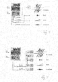
- FIG. 1 3 shows a schematic view of the construction of a device E for controlling and / or monitoring decentralized functional units DFE1A to DFEnA arranged along a railway network (not shown here), DFE1B to DFEnB, etc. (hereafter referred to as Element Controller EC).
- the decentralized functional units are hereinafter referred to as DFE.
- Such decentralized functional units DFE are used to control and monitor train-influencing and / or train monitoring units.
- signals, switches, balises, line conductors, track magnets and the like may be mentioned.
- Train monitoring units can also include balises and line conductors, as well as axle counters and track circuits.
- a signal S is controlled and monitored by the decentralized functional unit DFE1C.
- the decentralized function unit DFE 1C controls the display of the signal terms and performs respectively assisted in monitoring functions, such as the monitoring of the lamp current in the signal.
- Each distributed functional unit DFE or the controlled / monitored unit has a unique address throughout the network, for example an IP address or a MAC address.
- the device E further comprises a data transport network TN with a number of network access points 2 to 16. At a portion of these network access points 6 to 16 communication units 18 to 28 are connected.
- the data transport network TN is designed here as a highly available network. Such highly available structures can arise on the one hand by a redundant design of the network itself and / or on the other hand by a clever re-organization of the network in the event of failure of a connector.
- the device E comprises a higher-level control system 30, which in addition to other components not further listed here a control center LT, a Stelltechnikrechner STW, an axle counting computer AZ and a service / diagnostic unit SD includes, which are connected via the network access points 2 and 4 by means of Ethernet connections to the data transport network TN.
- the decentralized functional units DFE must be coupled to the transport network TN via one of the communication groups 18 to 28 and the corresponding network node 6 to 16 and can thus receive or exchange data telegrams via this.
- the decentralized functional units DFE are combined to subgroups A, B, C, D and E, each with its own subnetwork NA, NB, NC, ND and NE.
- the subgroup A is formed, for example, from the decentralized functional units DFE1A, DFE2A, DFE3A to DFEnA.
- the subgroups A to E are always connected at their two ends with one of the communication groups 18 to 28 and a network access points 6 to 16.
- Each decentralized functional unit DFE is also a switching computer SU, which may alternatively be integrated directly into the decentralized functional unit DFE upstream, which provides the connection to the subnetwork for the decentralized functional units DFE, so that each decentralized functional unit DFE in case of failure of a communication group of one second redundant communication group 18 to 28 can be addressed.
- Each subnetwork (NA to NE) is thus made up of a number of point-to-point connections of logically adjacent distributed functional units (DFE).
- DFE distributed functional units
- a point-to-point connection is formed as an autonomous transmission path within the subnetwork, for example as an ISDN transmission path or as an xDSL transmission path or fiber optic transmission path.
- a single subnetwork can be constructed, so to speak, of individual transmission cells, which in turn always only control the transmission from point to point have to. In other words, for example, from simple, rather short-range transmission techniques, a much longer and more complex subnetwork can be put together.
- a suitable switching module (SU) may for this purpose be designed such that it provides a number of point-to-point transmission techniques and, depending on the circuitry, self-organizingly provides the point-to-point transmission technique determined by the circuitry.
- the subgroups A to E are each connected to a first connection type or a second connection type to the two communication groups 18 to 28.
- first type of connection as shown for subgroups A, C and E, for example, the associated subnetwork NA, NC and NE are terminated in two geographically close communication groups 18 and 20 or 22 and 24 or 26 and 28, respectively FIG. 1 should be shown by the immediate vicinity of the communication group pairs 18, 20 and 22, 24 and 26, 28.
- second type of connection as shown for subgroups B and D, the respective subnetwork NB or ND is terminated with the communication groups 20, 22 or 24, 26 that are located further apart from each other.
- each subgroup B and D is still connected to another communication group in case of failure of one of the two associated communication groups.
- the network access points 6, 8 and 10, 12 and 14, 16 are respectively arranged at stations of the railway network, then provide the subgroups A, C and E rather in the station area arranged decentralized functional units DFE.
- the subgroups B and D represent more such decentralized functional units DFE, which are arranged in the area between two stations on a free route.
- the copper cables, which are too large can be used to save energy, which is explained using the example of subgroup B.
- the decentralized functional units DFE1B, DFE2B and DFE3B were driven from the station at the network access point 8.
- the remaining decentralized network access points DFEnB were controlled from the station at the network access point 10.
- the establishment of a connection sufficed only between the decentralized functional units DFE3B and DFEnB in order to interconnect the subgroup B in the subnetwork NB.
- the telegram types have assigned fixed timeslots.
- the assignment can be fixed during operation and can be configured offline, for example in the ratio of at least 1 to 10.
- FIG. 2 now shows the situation according to FIG. 1 in a simplified representation.
- the element controllers EC are connected to the data transport network TN for data purposes and are supplied directly with electrical energy from a central signal box zST or from decentralized stations DS1 to DSn via a universal voltage supply UPS.
- This embodiment thus still depends on the flaw that certain adjustment distances can not be realized with this supply solution. An example of this is the distance of about 6.5 km, to the Signal lamps can still be reliably monitored by the flowing lamp current.
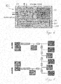
- FIG. 3 now shows a schematic representation of the according to FIG. 1 only data-technically valid situation with the inventive energy supply concept. All element controllers are now on the same power transport network ETN. The supply of electrical energy is now no longer exclusively from the central interlocking, but also via external power supplies UPS ', but otherwise no longer have any relation to the data processing of the element controller EC.
- intelligent energy stores IES1 to IES4 are now connected to the electrotransport network ETN and the data transport network TN, so that these intelligent energy stores IES1 to IES4 can communicate with the central signal box zST via the data transport network TN and thus a power consumption and / or output can be controlled by an implemented in the logic of the central signal box zST energy manager IEM.
- the intelligent energy storage IES1 to IES4 have next to a charging device with inverter LE and the actual energy storage ES via a local logic module LM, a regulation of an energy flow REF and a communication module COM (see. FIG. 6 ).
- FIG. 4 schematically shows the connection of field elements, such as railroad crossing, signal, switch and Achstappedddling, according to the prior art.
- the STW interlocking computer leaves up to 40 cable cores for power supply and data communication.
- a signal accordingly has 2 to 32 cable cores, one crossover via four cable cores and one axis crosspoint via up to 4 cable cores.
- FIG. 5 From the new STW interlocking computer for the same field elements, only four cable cores for the electrical energy and up to four cable cores for the communication are used.
- the interlocking computer as in FIG. 1 represented connected via a network access point 2 to the data transport network TN.
- the FIG. 7 shows by way of example the result of a simulation calculation for a scalable in terms of field elements and the energy storage situation in the track area.
- Scalable cable models and scalable energy levelers are also used.
- energy storage and mechanical flywheel storage and super capacitors can be used.
- the FIG. 7 Therefore, also shows the benefits of the present concept of decentralized distributed energy storage in the energy transport network, so that the design of the energy transport network can use the contribution of the energy storage to the effect that the wires of the network must be designed only for a predeterminable basic performance.
Landscapes
- Engineering & Computer Science (AREA)
- Mechanical Engineering (AREA)
- Power Engineering (AREA)
- Train Traffic Observation, Control, And Security (AREA)
- Supply And Distribution Of Alternating Current (AREA)
- Selective Calling Equipment (AREA)
Priority Applications (4)
| Application Number | Priority Date | Filing Date | Title |
|---|---|---|---|
| EP11189530.6A EP2549620A3 (fr) | 2011-07-22 | 2011-11-17 | Dispositif de fonctionnement d'unités de fonction décentralisées et agencées dans une installation industrielle |
| PCT/EP2012/062007 WO2013013908A2 (fr) | 2011-07-22 | 2012-06-21 | Dispositif permettant de faire fonctionner des unités fonctionnelles décentralisées disposées dans une installation industrielle |
| EP12733010.8A EP2735082B1 (fr) | 2011-07-22 | 2012-06-21 | Dispositif permettant de faire fonctionner des unités fonctionnelles décentralisées disposées dans une infrastructure ferroviaire |
| US14/234,307 US9156484B2 (en) | 2011-07-22 | 2012-06-21 | Device for operating decentralized functional units arranged in an industrial installation |
Applications Claiming Priority (2)
| Application Number | Priority Date | Filing Date | Title |
|---|---|---|---|
| EP11174992 | 2011-07-22 | ||
| EP11189530.6A EP2549620A3 (fr) | 2011-07-22 | 2011-11-17 | Dispositif de fonctionnement d'unités de fonction décentralisées et agencées dans une installation industrielle |
Publications (2)
| Publication Number | Publication Date |
|---|---|
| EP2549620A2 true EP2549620A2 (fr) | 2013-01-23 |
| EP2549620A3 EP2549620A3 (fr) | 2013-04-24 |
Family
ID=45315493
Family Applications (2)
| Application Number | Title | Priority Date | Filing Date |
|---|---|---|---|
| EP11189530.6A Withdrawn EP2549620A3 (fr) | 2011-07-22 | 2011-11-17 | Dispositif de fonctionnement d'unités de fonction décentralisées et agencées dans une installation industrielle |
| EP12733010.8A Active EP2735082B1 (fr) | 2011-07-22 | 2012-06-21 | Dispositif permettant de faire fonctionner des unités fonctionnelles décentralisées disposées dans une infrastructure ferroviaire |
Family Applications After (1)
| Application Number | Title | Priority Date | Filing Date |
|---|---|---|---|
| EP12733010.8A Active EP2735082B1 (fr) | 2011-07-22 | 2012-06-21 | Dispositif permettant de faire fonctionner des unités fonctionnelles décentralisées disposées dans une infrastructure ferroviaire |
Country Status (3)
| Country | Link |
|---|---|
| US (1) | US9156484B2 (fr) |
| EP (2) | EP2549620A3 (fr) |
| WO (1) | WO2013013908A2 (fr) |
Cited By (8)
| Publication number | Priority date | Publication date | Assignee | Title |
|---|---|---|---|---|
| WO2015000757A1 (fr) * | 2013-07-02 | 2015-01-08 | Siemens Schweiz Ag | Équipement et procédé pour faire fonctionner des unités fonctionnelles décentralisées |
| EP3109125A1 (fr) * | 2015-06-25 | 2016-12-28 | Siemens Schweiz AG | Système et procédé d'alimentation d'unités de fonctionnement décentralisées en énergie électrique |
| EP3109128A1 (fr) * | 2015-06-25 | 2016-12-28 | Siemens Schweiz AG | Système et procédé d'élimination de court-circuit dans un bus d'alimentation |
| NL2018835A (nl) * | 2016-05-05 | 2017-11-10 | Volkerrail Nederland Bv | Relaishuis of relaiskasthuis met EtherCat systeem. |
| WO2018059881A1 (fr) * | 2016-09-27 | 2018-04-05 | Siemens Aktiengesellschaft | Système et procédé pour faire fonctionner des éléments de champ montés de manière décentralisée dans une voie ferrée |
| AT16035U1 (de) * | 2016-05-18 | 2018-11-15 | Thales Deutschland Gmbh | Stromversorgungseinrichtung |
| EP3590786A1 (fr) * | 2018-07-05 | 2020-01-08 | Siemens Mobility AG | Procédé d'échange sécurisé et d'affichage sécurisé de données d'état des composants de sécurité |
| EP3822145A1 (fr) * | 2019-11-13 | 2021-05-19 | Siemens Mobility AG | Procédé et système d'exécution d'un chemin de roulement à aiguillage projeté |
Families Citing this family (12)
| Publication number | Priority date | Publication date | Assignee | Title |
|---|---|---|---|---|
| US11814088B2 (en) | 2013-09-03 | 2023-11-14 | Metrom Rail, Llc | Vehicle host interface module (vHIM) based braking solutions |
| CN107364434A (zh) | 2013-09-03 | 2017-11-21 | 梅特罗姆铁路公司 | 铁路车辆信号执行和分离控制 |
| FR3025480B1 (fr) * | 2014-09-04 | 2016-12-23 | Alstom Transp Tech | Infrastructure de radiocommunication pour un systeme de signalisation ferroviaire du type cbtc |
| EP3150461A1 (fr) | 2015-10-02 | 2017-04-05 | Siemens Schweiz AG | Système et procédé d'élimination automatique d'une tension induite excessive dans un bus de puissance |
| PT3247015T (pt) | 2016-05-18 | 2020-01-27 | Thales Man & Services Deutschland Gmbh | Dispositivo de abastecimento de corrente e processo para a operação de um dispositivo de abastecimento de corrente |
| EP3490870A1 (fr) * | 2016-09-19 | 2019-06-05 | Siemens Mobility GmbH | Système, unité de prédiction et procédé de prédiction d'une défaillance d'au moins une unité de surveillance et/ou de commande de trafic de transport |
| EP3305622A1 (fr) | 2016-10-06 | 2018-04-11 | Siemens Schweiz AG | Procédé de diagnostic de composants techniques répartis dans l'espace |
| EP3415399B1 (fr) | 2017-06-16 | 2019-10-23 | Siemens Mobility AG | Système d'alimentation à sureté intégrée d'un consommateur électrique à l'aide d'un bus d'énergie redondant |
| US11349589B2 (en) | 2017-08-04 | 2022-05-31 | Metrom Rail, Llc | Methods and systems for decentralized rail signaling and positive train control |
| CA3071985A1 (fr) * | 2017-08-04 | 2019-02-07 | Metrom Rail, Llc | Procedes et systemes pour commande decentralisee de train |
| EP4037126B1 (fr) | 2021-01-29 | 2026-01-21 | Siemens Mobility AG | Système de démarrage rapide commandé et de fonctionnement d'un bus à énergie redondant destiné à l'alimentation à sécurité intégrée d'un consommateur électrique |
| EP4160845B1 (fr) | 2021-09-29 | 2024-04-17 | Siemens Mobility AG | Système de démarrage contrôlé et de fonctionnement d'un bus d'énergie redondant |
Citations (1)
| Publication number | Priority date | Publication date | Assignee | Title |
|---|---|---|---|---|
| EP2301202A1 (fr) | 2007-05-24 | 2011-03-30 | Siemens Schweiz AG | Dispositif de commande et/ou de surveillance et de demande de données d'unités fonctionnelles décentralisées le long d'un réseau de communication |
Family Cites Families (9)
| Publication number | Priority date | Publication date | Assignee | Title |
|---|---|---|---|---|
| DE19733765A1 (de) * | 1997-08-05 | 1999-02-11 | Alsthom Cge Alcatel | Verfahren zur Kommunikation zwischen einem im Bereich einer Schienenstrecke angeordneten Feldelement und einer zentralen Überwachungseinheit sowie Kommunikationssystem und Sendeempfangseinheit hierfür |
| JP3352662B2 (ja) * | 2000-02-03 | 2002-12-03 | 関西電力株式会社 | 二次電池システムを用いた電力系統安定化装置および電力系統安定化方法 |
| JP4848132B2 (ja) * | 2005-03-31 | 2011-12-28 | 東日本旅客鉄道株式会社 | 信号制御システム、信号機器及びプログラム |
| US20100306097A1 (en) * | 2007-09-21 | 2010-12-02 | Siemens Aktiengesellschaft | Decentralized energy system and method for distributing energy in a decentralized energy system |
| FR2926141B1 (fr) * | 2008-01-03 | 2010-03-19 | Commissariat Energie Atomique | Procede pour l'amelioration de la precision de detection et de localisation de defauts par reflectometrie dans un reseau electrique cable |
| DE102008024489A1 (de) * | 2008-05-21 | 2009-12-10 | Siemens Aktiengesellschaft | Schiff mit einem Schiffssystem mit einer zentralen Steuerung |
| DE102008044902A1 (de) * | 2008-08-29 | 2010-03-04 | Siemens Aktiengesellschaft | Vorrichtung und Verfahren zur Erzeugung, Speicherung und Übertragung von elektrischer Energie |
| US8324859B2 (en) * | 2008-12-15 | 2012-12-04 | Comverge, Inc. | Method and system for co-operative charging of electric vehicles |
| DE102009057704A1 (de) * | 2009-12-04 | 2011-06-09 | Siemens Aktiengesellschaft | Stromversorgungseinrichtung für einen Weichenantrieb |
-
2011
- 2011-11-17 EP EP11189530.6A patent/EP2549620A3/fr not_active Withdrawn
-
2012
- 2012-06-21 US US14/234,307 patent/US9156484B2/en not_active Expired - Fee Related
- 2012-06-21 EP EP12733010.8A patent/EP2735082B1/fr active Active
- 2012-06-21 WO PCT/EP2012/062007 patent/WO2013013908A2/fr not_active Ceased
Patent Citations (1)
| Publication number | Priority date | Publication date | Assignee | Title |
|---|---|---|---|---|
| EP2301202A1 (fr) | 2007-05-24 | 2011-03-30 | Siemens Schweiz AG | Dispositif de commande et/ou de surveillance et de demande de données d'unités fonctionnelles décentralisées le long d'un réseau de communication |
Cited By (16)
| Publication number | Priority date | Publication date | Assignee | Title |
|---|---|---|---|---|
| AU2014286412B2 (en) * | 2013-07-02 | 2017-02-23 | Siemens Schweiz Ag | Device and method for operating functional units arranged in a decentralized manner |
| EP2821313A3 (fr) * | 2013-07-02 | 2015-05-06 | Siemens Schweiz AG | Dispositif et procédé de fonctionnement d'unités fonctionnelles disposées de façon décentralisée |
| CN105358403A (zh) * | 2013-07-02 | 2016-02-24 | 瑞士西门子有限公司 | 用于运行分散式设置的功能单元的装置和方法 |
| US10407086B2 (en) | 2013-07-02 | 2019-09-10 | Siemens Mobility Ag | Device and method for operating functional units arranged in a decentralized manner |
| WO2015000757A1 (fr) * | 2013-07-02 | 2015-01-08 | Siemens Schweiz Ag | Équipement et procédé pour faire fonctionner des unités fonctionnelles décentralisées |
| EP3109128A1 (fr) * | 2015-06-25 | 2016-12-28 | Siemens Schweiz AG | Système et procédé d'élimination de court-circuit dans un bus d'alimentation |
| WO2016206842A1 (fr) * | 2015-06-25 | 2016-12-29 | Siemens Schweiz Ag | Système et procédé d'alimentation électrique d'unités fonctionnelles décentralisées |
| WO2016206843A1 (fr) * | 2015-06-25 | 2016-12-29 | Siemens Schweiz Ag | Système et procédé de suppression automatique de courts-circuits dans un bus d'alimentaton |
| EP3109125A1 (fr) * | 2015-06-25 | 2016-12-28 | Siemens Schweiz AG | Système et procédé d'alimentation d'unités de fonctionnement décentralisées en énergie électrique |
| NL2018835A (nl) * | 2016-05-05 | 2017-11-10 | Volkerrail Nederland Bv | Relaishuis of relaiskasthuis met EtherCat systeem. |
| EP3257718A1 (fr) * | 2016-05-05 | 2017-12-20 | VolkerRail Nederland BV | Logement ou armoire de relais doté d'un système ethercat |
| AT16035U1 (de) * | 2016-05-18 | 2018-11-15 | Thales Deutschland Gmbh | Stromversorgungseinrichtung |
| WO2018059881A1 (fr) * | 2016-09-27 | 2018-04-05 | Siemens Aktiengesellschaft | Système et procédé pour faire fonctionner des éléments de champ montés de manière décentralisée dans une voie ferrée |
| EP3590786A1 (fr) * | 2018-07-05 | 2020-01-08 | Siemens Mobility AG | Procédé d'échange sécurisé et d'affichage sécurisé de données d'état des composants de sécurité |
| WO2020007532A1 (fr) * | 2018-07-05 | 2020-01-09 | Siemens Mobility Ag | Procédé d'échange sécurisé et d'affichage sécurisé de données d'état de composants de sécurité |
| EP3822145A1 (fr) * | 2019-11-13 | 2021-05-19 | Siemens Mobility AG | Procédé et système d'exécution d'un chemin de roulement à aiguillage projeté |
Also Published As
| Publication number | Publication date |
|---|---|
| EP2549620A3 (fr) | 2013-04-24 |
| EP2735082B1 (fr) | 2022-02-16 |
| EP2735082A2 (fr) | 2014-05-28 |
| US20140191089A1 (en) | 2014-07-10 |
| WO2013013908A3 (fr) | 2013-05-16 |
| US9156484B2 (en) | 2015-10-13 |
| WO2013013908A2 (fr) | 2013-01-31 |
Similar Documents
| Publication | Publication Date | Title |
|---|---|---|
| EP2735082B1 (fr) | Dispositif permettant de faire fonctionner des unités fonctionnelles décentralisées disposées dans une infrastructure ferroviaire | |
| EP2301202B1 (fr) | Dispositif de commande et/ou de surveillance et de demande de données à partir d'unités de fonction décentralisées agencées le long d'un réseau de trafic | |
| EP2821313A2 (fr) | Dispositif et procédé de fonctionnement d'unités fonctionnelles disposées de façon décentralisée | |
| EP2057056B1 (fr) | Procédé et dispositif destinés à un système adaptatif modulaire de commande et de contrôle d'installations de sécurisation de chemin de fer | |
| DE3323269A1 (de) | Einrichtung zum betrieb eines rechnergesteuerten stellwerkes | |
| EP1719688A1 (fr) | Système de transmission de données pour véhicules ferroviaires | |
| DE102007003196A1 (de) | Kommunikationssystem | |
| EP3415399B1 (fr) | Système d'alimentation à sureté intégrée d'un consommateur électrique à l'aide d'un bus d'énergie redondant | |
| EP3313709A1 (fr) | Système et procédé d'alimentation électrique d'unités fonctionnelles décentralisées | |
| WO2000076829A1 (fr) | Installation de securite pour passage a niveau | |
| EP3822145B1 (fr) | Procédé et système pour traiter une chaine d'appareils d'aiguillage | |
| EP2674346B1 (fr) | Procédé et système d'approvisionnement de puissance électrique pour des éléments de voie décentralisés d'un réseau de voies ferrées | |
| EP2613476B1 (fr) | Procédé de redondance pour un réseau de données spécialisé | |
| EP3383723A1 (fr) | Dispositif et procédé de commande et/ou de surveillance d'unités fonctionnelles intelligentes décentralisées agencées dans un réseau ferroviaire | |
| DE102016217774A1 (de) | Sicherungseinrichtung für einen Bahnübergang | |
| EP3305622A1 (fr) | Procédé de diagnostic de composants techniques répartis dans l'espace | |
| DE19847901C1 (de) | Datenübertragungssystem für die Ausbausteuerung eines Gewinnungsbetriebs im Untertagebergbau | |
| EP3739407A1 (fr) | Procédé d'ajustement d'une topologie de communication dans un système cyberphysique | |
| EP4458646A1 (fr) | Adaptateur de jeu de relais avec élément de réglage pour migration d'enclenchement | |
| DE102008003439B4 (de) | Verkehrssignalisierungsmodul, Verkehrssignalisierungssystem und Verfahren zum Betrieb eines Verkehrssignalisierungssystems | |
| WO1999022278A1 (fr) | Dispositif de transmission de donnees destine a la commande ou a la regulation d'un processus industriel | |
| EP1265147A2 (fr) | Configuration de bus pour un bus universel de signalisation et commande | |
| DE102011003364A1 (de) | Eisenbahnsicherungssystem | |
| DD223416A1 (de) | System eines automatischen streckenblocks mit zentraler informationsverarbeitung |
Legal Events
| Date | Code | Title | Description |
|---|---|---|---|
| PUAI | Public reference made under article 153(3) epc to a published international application that has entered the european phase |
Free format text: ORIGINAL CODE: 0009012 |
|
| AK | Designated contracting states |
Kind code of ref document: A2 Designated state(s): AL AT BE BG CH CY CZ DE DK EE ES FI FR GB GR HR HU IE IS IT LI LT LU LV MC MK MT NL NO PL PT RO RS SE SI SK SM TR |
|
| AX | Request for extension of the european patent |
Extension state: BA ME |
|
| PUAL | Search report despatched |
Free format text: ORIGINAL CODE: 0009013 |
|
| AK | Designated contracting states |
Kind code of ref document: A3 Designated state(s): AL AT BE BG CH CY CZ DE DK EE ES FI FR GB GR HR HU IE IS IT LI LT LU LV MC MK MT NL NO PL PT RO RS SE SI SK SM TR |
|
| AX | Request for extension of the european patent |
Extension state: BA ME |
|
| RIC1 | Information provided on ipc code assigned before grant |
Ipc: B61L 19/06 20060101ALI20130318BHEP Ipc: B61L 27/00 20060101ALI20130318BHEP Ipc: B61L 3/00 20060101AFI20130318BHEP |
|
| STAA | Information on the status of an ep patent application or granted ep patent |
Free format text: STATUS: THE APPLICATION IS DEEMED TO BE WITHDRAWN |
|
| 18D | Application deemed to be withdrawn |
Effective date: 20131025 |