EP2549632A2 - Linearschrittmotor - Google Patents
Linearschrittmotor Download PDFInfo
- Publication number
- EP2549632A2 EP2549632A2 EP12168919A EP12168919A EP2549632A2 EP 2549632 A2 EP2549632 A2 EP 2549632A2 EP 12168919 A EP12168919 A EP 12168919A EP 12168919 A EP12168919 A EP 12168919A EP 2549632 A2 EP2549632 A2 EP 2549632A2
- Authority
- EP
- European Patent Office
- Prior art keywords
- nut shaft
- step motor
- coupled
- linear step
- cover member
- Prior art date
- Legal status (The legal status is an assumption and is not a legal conclusion. Google has not performed a legal analysis and makes no representation as to the accuracy of the status listed.)
- Granted
Links
Images

Classifications
-
- H—ELECTRICITY
- H02—GENERATION; CONVERSION OR DISTRIBUTION OF ELECTRIC POWER
- H02K—DYNAMO-ELECTRIC MACHINES
- H02K37/00—Motors with rotor rotating step by step and without interrupter or commutator driven by the rotor, e.g. stepping motors
- H02K37/10—Motors with rotor rotating step by step and without interrupter or commutator driven by the rotor, e.g. stepping motors of permanent magnet type
- H02K37/12—Motors with rotor rotating step by step and without interrupter or commutator driven by the rotor, e.g. stepping motors of permanent magnet type with stationary armatures and rotating magnets
- H02K37/14—Motors with rotor rotating step by step and without interrupter or commutator driven by the rotor, e.g. stepping motors of permanent magnet type with stationary armatures and rotating magnets with magnets rotating within the armatures
-
- H—ELECTRICITY
- H02—GENERATION; CONVERSION OR DISTRIBUTION OF ELECTRIC POWER
- H02K—DYNAMO-ELECTRIC MACHINES
- H02K1/00—Details of the magnetic circuit
- H02K1/06—Details of the magnetic circuit characterised by the shape, form or construction
- H02K1/22—Rotating parts of the magnetic circuit
- H02K1/28—Means for mounting or fastening rotating magnetic parts on to, or to, the rotor structures
-
- H—ELECTRICITY
- H02—GENERATION; CONVERSION OR DISTRIBUTION OF ELECTRIC POWER
- H02K—DYNAMO-ELECTRIC MACHINES
- H02K41/00—Propulsion systems in which a rigid body is moved along a path due to dynamo-electric interaction between the body and a magnetic field travelling along the path
- H02K41/02—Linear motors; Sectional motors
-
- F—MECHANICAL ENGINEERING; LIGHTING; HEATING; WEAPONS; BLASTING
- F16—ENGINEERING ELEMENTS AND UNITS; GENERAL MEASURES FOR PRODUCING AND MAINTAINING EFFECTIVE FUNCTIONING OF MACHINES OR INSTALLATIONS; THERMAL INSULATION IN GENERAL
- F16C—SHAFTS; FLEXIBLE SHAFTS; ELEMENTS OR CRANKSHAFT MECHANISMS; ROTARY BODIES OTHER THAN GEARING ELEMENTS; BEARINGS
- F16C35/00—Rigid support of bearing units; Housings, e.g. caps, covers
- F16C35/04—Rigid support of bearing units; Housings, e.g. caps, covers in the case of ball or roller bearings
- F16C35/06—Mounting or dismounting of ball or roller bearings; Fixing them onto shaft or in housing
- F16C35/063—Fixing them on the shaft
-
- H—ELECTRICITY
- H02—GENERATION; CONVERSION OR DISTRIBUTION OF ELECTRIC POWER
- H02K—DYNAMO-ELECTRIC MACHINES
- H02K7/00—Arrangements for handling mechanical energy structurally associated with dynamo-electric machines, e.g. structural association with mechanical driving motors or auxiliary dynamo-electric machines
- H02K7/003—Couplings; Details of shafts
-
- H—ELECTRICITY
- H02—GENERATION; CONVERSION OR DISTRIBUTION OF ELECTRIC POWER
- H02K—DYNAMO-ELECTRIC MACHINES
- H02K7/00—Arrangements for handling mechanical energy structurally associated with dynamo-electric machines, e.g. structural association with mechanical driving motors or auxiliary dynamo-electric machines
- H02K7/06—Means for converting reciprocating motion into rotary motion or vice versa
-
- H—ELECTRICITY
- H02—GENERATION; CONVERSION OR DISTRIBUTION OF ELECTRIC POWER
- H02K—DYNAMO-ELECTRIC MACHINES
- H02K7/00—Arrangements for handling mechanical energy structurally associated with dynamo-electric machines, e.g. structural association with mechanical driving motors or auxiliary dynamo-electric machines
- H02K7/08—Structural association with bearings
- H02K7/085—Structural association with bearings radially supporting the rotary shaft at only one end of the rotor
-
- Y—GENERAL TAGGING OF NEW TECHNOLOGICAL DEVELOPMENTS; GENERAL TAGGING OF CROSS-SECTIONAL TECHNOLOGIES SPANNING OVER SEVERAL SECTIONS OF THE IPC; TECHNICAL SUBJECTS COVERED BY FORMER USPC CROSS-REFERENCE ART COLLECTIONS [XRACs] AND DIGESTS
- Y10—TECHNICAL SUBJECTS COVERED BY FORMER USPC
- Y10T—TECHNICAL SUBJECTS COVERED BY FORMER US CLASSIFICATION
- Y10T74/00—Machine element or mechanism
- Y10T74/18—Mechanical movements
- Y10T74/18568—Reciprocating or oscillating to or from alternating rotary
- Y10T74/18576—Reciprocating or oscillating to or from alternating rotary including screw and nut
- Y10T74/18584—Shaft shorter than nut
-
- Y—GENERAL TAGGING OF NEW TECHNOLOGICAL DEVELOPMENTS; GENERAL TAGGING OF CROSS-SECTIONAL TECHNOLOGIES SPANNING OVER SEVERAL SECTIONS OF THE IPC; TECHNICAL SUBJECTS COVERED BY FORMER USPC CROSS-REFERENCE ART COLLECTIONS [XRACs] AND DIGESTS
- Y10—TECHNICAL SUBJECTS COVERED BY FORMER USPC
- Y10T—TECHNICAL SUBJECTS COVERED BY FORMER US CLASSIFICATION
- Y10T74/00—Machine element or mechanism
- Y10T74/18—Mechanical movements
- Y10T74/18568—Reciprocating or oscillating to or from alternating rotary
- Y10T74/18576—Reciprocating or oscillating to or from alternating rotary including screw and nut
- Y10T74/186—Alternate power path operable on failure of primary
-
- Y—GENERAL TAGGING OF NEW TECHNOLOGICAL DEVELOPMENTS; GENERAL TAGGING OF CROSS-SECTIONAL TECHNOLOGIES SPANNING OVER SEVERAL SECTIONS OF THE IPC; TECHNICAL SUBJECTS COVERED BY FORMER USPC CROSS-REFERENCE ART COLLECTIONS [XRACs] AND DIGESTS
- Y10—TECHNICAL SUBJECTS COVERED BY FORMER USPC
- Y10T—TECHNICAL SUBJECTS COVERED BY FORMER US CLASSIFICATION
- Y10T74/00—Machine element or mechanism
- Y10T74/18—Mechanical movements
- Y10T74/18568—Reciprocating or oscillating to or from alternating rotary
- Y10T74/18576—Reciprocating or oscillating to or from alternating rotary including screw and nut
- Y10T74/18664—Shaft moves through rotary drive means
-
- Y—GENERAL TAGGING OF NEW TECHNOLOGICAL DEVELOPMENTS; GENERAL TAGGING OF CROSS-SECTIONAL TECHNOLOGIES SPANNING OVER SEVERAL SECTIONS OF THE IPC; TECHNICAL SUBJECTS COVERED BY FORMER USPC CROSS-REFERENCE ART COLLECTIONS [XRACs] AND DIGESTS
- Y10—TECHNICAL SUBJECTS COVERED BY FORMER USPC
- Y10T—TECHNICAL SUBJECTS COVERED BY FORMER US CLASSIFICATION
- Y10T74/00—Machine element or mechanism
- Y10T74/18—Mechanical movements
- Y10T74/18568—Reciprocating or oscillating to or from alternating rotary
- Y10T74/18576—Reciprocating or oscillating to or from alternating rotary including screw and nut
- Y10T74/18688—Limit stop
Definitions
- the present disclosure is directed to a linear step motor.
- a step motor or a stepping motor is a digital actuator rotating or linearly moving at a predetermined angle, where a motor rotating at a predetermined angle is called a step motor while a motor moving linearly at a predetermined angle is called a linear step motor.
- the linear step motor is advantageous in that a rotation angle can be precisely controlled due to the number of input pulses being in proportion to a rotation angle of motor.
- the linear step motor is largely used for Numerical Control machine or OA (Office Automation) devices such as industrial robots, printers and/or copiers.
- a linear step motor structurally includes a housing, a control part mounted outside of the housing, a stator part mounted inside the housing, a rotor module rotatably mounted inside the stator part by way of electromagnetic force, and a lead screw linearly mounted in association with a rotation motion of the rotor module.
- the rotor module includes a magnet rotatably mounted inside a tooth yoke forming the stator part at a predetermined gap, and a nut shaft rotatably mounted inside the magnet in association with the magnet and formed with female screw threads.
- the lead screw is formed at a periphery with male screw threads meshed with the female screw threads of the nut shaft to enable a linear movement (forward and backward movement) in response to rotation of the nut shaft.
- the rotor module needs a wave washer, a spacer and an E-ring about a bearing mounted at a cover member in order to fix the nut shaft on the cover member opening/closing an opening of the housing at the linear step motor.
- efficiency of assembly process may deteriorate, relevant parts may be lost in the assembly process and difficulty in parts management may arise due to maintenance of a large number of parts.
- Another problem is that parts may be omitted in the assembly process, such that improvement on assembly process of rotor module is badly required.
- the present disclosure has been made to solve the foregoing problems of the prior art and therefore an object of certain embodiments of the present invention is to provide a linear step motor configured to reduce the number of parts, to simplify an assembly process and to improve a structure of the linear step motor.
- a linear step motor comprising: a motor housing fixedly mounted at an inner surface of a ring-shaped stator and formed with an opening; a rotor rotatably mounted at a space centrally formed at the stator; a cover member coupled to a bearing to open/close the opening; a nut shaft centrally arranged at the rotor, coupled to an outside of the cover member by passing through a shaft hole centrally formed at an inner ring of the bearing, coupled at a periphery by a magnet and formed with a female screw gear-combined with a lead screw member formed at an inner surface with a male screw; and a fixing unit integrally formed with the nut shaft and fixed to the bearing coupled to the cover member.
- the fixing unit includes a plurality of hook members integrally formed at a distal end of the nut shaft, a stopper interposed between the distal end of the nut shaft and the hook member to prevent the nut shaft from being inserted into the cover member at an abnormal coupling position; and a guide surface formed at a surface opposite to the hook members.
- the hook member includes a hook body integrally formed with the nut shaft, a sliding inclination surface formed at a surface opposite to the cover member at a distal end of the hook body, and a hitching sill hooked at an inner ring of the bearing coupled to the cover member at a nut shaft fixing position of the cover member.
- a pair of hook members whose guide surfaces face each other, is protrusively formed at a distal end of the nut shaft.
- each of the hook members is arranged at a 90° interval at an upper circumference of nut shaft, such that a total of two pairs are protrusively formed at a distal end of the nut shaft.
- a distance from the stopper to the hitching sill corresponds to thickness of the bearing.
- the guide surface has an arc having a shape corresponding to an imaginary circle having as a diameter a distance from the guide surface formed at the facing hook member.
- the nut shaft is formed at some sections of inner surface with female screws.
- the nut shaft is integrally formed with the fixing unit by way of molding process.
- the motor housing includes a first housing formed with the stator and having an opening having a size corresponding to the stator, and a second housing coupled to an upper side of the first housing and having an upper opening having a size corresponding to a diameter of the rotor.
- the linear step motor according to the present disclosure has an advantageous effect in that an assembly process can be simplified and reduction in manufacturing cost can be expected because a nut shaft is directly coupled to a cover member free from coupling parts such as a wave washer, a spacer and an E-ring.
- Another advantage is that product defect caused by missing parts during assembly process can be prevented, because no separate parts are needed for the assembly process.
- FIGS. 1 -4 of the drawings like numerals being used for like and corresponding parts of the various drawings.
- Other features and advantages of the disclosed embodiments will be or will become apparent to one of ordinary skill in the art upon examination of the following figures and detailed description. It is intended that all such additional features and advantages be included within the scope of the disclosed embodiments, and protected by the accompanying drawings.
- the illustrated figures are only exemplary and not intended to assert or imply any limitation with regard to the environment, architecture, or process in which different embodiments may be implemented. Accordingly, the described aspect is intended to embrace all such alterations, modifications, and variations that fall within the scope and novel idea of the present invention.
- first a second constituent element
- first constituent element a first constituent element without departing from the scope and spirit of the present disclosure
- first constituent element may be denoted as a second constituent element.
- FIG.1 is a perspective view illustrating a linear step motor according an exemplary embodiment of the present disclosure
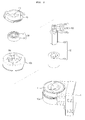
- FIG.2 is an exploded perspective view illustrating the linear step motor of FIG.1
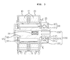
- FIG.3 is a cross-sectional view taken along line "A-A" of FIG.1 .
- a linear step motor includes a motor housing 10, a rotor 12, a cover member 20 and a bearing 30.
- the motor housing 10 includes first and second housings 10a, 10b.
- the first housing 10a as illustrated in FIG.1 , is provided in an upper-opened cylindrical shape, and is mounted therein with a stator 11.
- the stator 11 is provided in an approximately ring shape, and the rotor 12 is rotatably supported in a cylindrical space formed in a center of the stator 11.
- Two stators 11 are generally mounted, that is, one stator 11 is mounted at the first housing 10a side while the other stator 11 is mounted at the second housing 10b side.
- each of the two stators 11 has a same size and shape, and vertically (one in up and the other down) and symmetrically mounted, such that a diameter of a surface opposite to the first housing 10a of the second housing 10b corresponds to that of the first housing 10a.
- the second housing 10b is fixedly coupled to an upper side of the first housing 10a, where the first and second housings 10a, 10b are generally coupled and fixed by welding, for example. That is, a surface opposite to the first housing 10a of the second housing 10b is formed with a circular opening corresponding to that of the first housing 10a, and the other surface of the opening of the second housing 10b is formed with an upper opening having a diameter corresponding to that of the rotor 12.
- one lateral surface of the motor housing 10 formed by coupling of the first and second housings 10a, 10b is fixedly formed with a control module 1, where the control module 1 functions to intermittently supply a power to the stator 11 to control an operation of the step motor.
- the rotor 12 is rotatably mounted at a cylindrical space formed in a center of the stator 11, and includes a nut shaft 100 and a magnet 101.
- the nut shaft 100 as shown in FIGS. 2 and 3 , is provided in an approximately cylindrical shape, formed therein with a female screw 210 at some sections of the inner surface, and formed in a gear-combineable manner with a male screw of a lead screw (not shown).
- the nut shaft 100 is formed at a periphery with a plurality of lugs for preventing the magnet 101 from idly rotating at the nut shaft, and may be formed with a stopper in the plurality of lugs for restricting a fixed position of the magnet 101.
- the magnet 101 in a cylindrical shape is coupled to a periphery of the nut shaft 100.
- the magnet 101 is centrally formed with a through hole having a diameter corresponding to the periphery of the nut shaft 100, and the nut shaft 100 is insertedly and vertically coupled through the through hole.
- a lug accommodation groove complementarily formed with the lug be formed at an inner surface of the through hole of the magnet 100.
- the cover member 20 is fixedly coupled to an upper side of the second housing 10b, formed with a diameter corresponding to that of an outer ring 32 of the bearing 30, and centrally and protrusively formed with a bearing accommodation unit 21 insertedly coupled by the bearing 30 from a down side to an upper side.
- the bearing accommodation unit 21, as shown in FIG.2 is protrusively formed toward an upper side as much as a height corresponding to that of the bearing 30.
- the nut shaft 100 is coupled in a hooking manner to an inner ring 31 of the bearing 30 coupled to the cover member 20 using a fixing unit 200, where the fixing unit 200 includes a hook member 210, a stopper 220 and a guide surface 230.
- the hook member 210 is integrally formed at a distal end of the nut shaft 100, and includes a hook body 211, a sliding inclination surface 212 and a hitching sill 213.
- the hook body 211 is integrally formed with the nut shaft 100, and extended from a distal end of the nut shaft as much as a predetermined length.
- the sliding inclination surface 212 is formed at a surface opposite to the cover member 20 at a distal end of the hook body 211, and so formed as to cause generation of sliding relative to an insertion direction of the hook member 210.
- the hitching sill 213 is provided at an area where the sliding inclination surface 212 ends, and surface-contacts the inner ring 31of the bearing 30 coupled to the cover member 20 at a fixed position of the nut shaft 100 of the cover member 20, where the hook member 210 may be hooked to the inner ring 31 of the bearing 30.
- a pair of hook members 210 is preferably and protrusively formed at a distal end of the nut shaft 100 each oppositely in parallel with the guide surface 230, and according to an exemplary embodiment of the present disclosure, preferably, each of the hook members 210 is arranged at a 90° interval at an upper circumference of nut shaft 100, such that a total of two pairs are protrusively formed at a distal end of the nut shaft.
- the stopper 220 that is defined by a distal end of the nut shaft 100 is provided in between the nut shaft 100 and the hook body 211 of the hook member 210.
- the stopper 220 is exposed to an upper side of an upper opening 10c of the second housing 10b when the rotor 12 is centrally coupled to the stator 11 and the second housing 10b is coupled.
- the stopper 220 is provided to allow the hook member 210 to pass through the through hole centrally formed at the inner ring 31 of the bearing 30, and to allow the hitching sill 213 to maintain a surface contact with the inner ring 31.
- the stopper 220 surface-contacts a surface opposite to a surface surface-contacting the hitching sill 213 of the inner ring 31.
- each of the both sides of the inner ring 31 surface-contacts the stopper 220 and the hitching sill 213 to allow the nut shaft 100 to be fixedly coupled to a cover member 20 side fixedly coupled by the bearing 30.
- a distance from the stopper 220 to the hitching sill 213 preferably corresponds to thickness of the bearing 30 in order to allow the nut shaft 100 to be fixed without any shake.
- a guide surface 230 preferably has an arc having a shape corresponding to an imaginary circle having as a diameter a distance from the guide surface 230 formed at the facing hook member 210, which is to correspond a diameter of a lead screw (not shown) to a distance among the guide surfaces 230.
- the guide surface 230 is provided in an arc, reciprocating motion of the lead screw can be guided while friction with the lead screw is minimized.
- the fixing unit thus configured is preferably formed in an integral form with the nut shaft 100.
- the nut shaft 100 is preferably configured with a shape of the fixing unit 200 and injection-molded together.
- stator 11 is fixed inside the housing, and a control module 1 is conductively connected to the stator 11 at the lateral surface of the housing 10.
- the rotor 12 is inserted into a cylindrical space centrally formed at the stator 11.
- the coupled state of the nut shaft 100 and the magnet 101 forming the rotor 12 is not inserted into the space, but the bearing-mounted cover member 20 is coupled to the upper side of the upper housing 10b, and the nut shaft 100 is inserted from a bottom side to an upper side of the second housing 10b coupled by the cover member 20.
- the nut shaft 100 is hooked to the inner ring 31 of the bearing 30 coupled to an inner surface of the cover member 20 using the fixing unit 200 integrally formed with the distal end of the nut shaft 100.
- the rotor 12 is inserted into the space centrally formed at the stator mounted at an interior of the first housing 10a, and the first and second housings 10a, 10b are welded to finish the fixing work.
- the linear step motor according to the present disclosure has an industrial applicability in that an assembly process can be simplified and reduction in manufacturing cost can be expected, because the fixing unit 200 having the hook member 210 can be integrally formed at the distal end of the nut shaft 100 to allow the nut shaft 100 to be hooked to the bearing 30 coupled to the cover member 20, and coupling parts such as spring washers, spacers and E-rings can be removed to reduce manufacturing cost resultant from reduced number of parts.
Landscapes
- Engineering & Computer Science (AREA)
- Power Engineering (AREA)
- Physics & Mathematics (AREA)
- Chemical & Material Sciences (AREA)
- Combustion & Propulsion (AREA)
- Electromagnetism (AREA)
- Connection Of Motors, Electrical Generators, Mechanical Devices, And The Like (AREA)
- Transmission Devices (AREA)
- Motor Or Generator Frames (AREA)
Applications Claiming Priority (1)
| Application Number | Priority Date | Filing Date | Title |
|---|---|---|---|
| KR1020110072974A KR101821817B1 (ko) | 2011-07-22 | 2011-07-22 | 리니어 스텝모터 |
Publications (3)
| Publication Number | Publication Date |
|---|---|
| EP2549632A2 true EP2549632A2 (de) | 2013-01-23 |
| EP2549632A3 EP2549632A3 (de) | 2016-07-20 |
| EP2549632B1 EP2549632B1 (de) | 2019-10-09 |
Family
ID=46172691
Family Applications (1)
| Application Number | Title | Priority Date | Filing Date |
|---|---|---|---|
| EP12168919.4A Active EP2549632B1 (de) | 2011-07-22 | 2012-05-22 | Linearschrittmotor |
Country Status (5)
| Country | Link |
|---|---|
| US (1) | US8950278B2 (de) |
| EP (1) | EP2549632B1 (de) |
| JP (1) | JP6058921B2 (de) |
| KR (1) | KR101821817B1 (de) |
| CN (1) | CN102891584B (de) |
Cited By (1)
| Publication number | Priority date | Publication date | Assignee | Title |
|---|---|---|---|---|
| WO2017006353A1 (en) * | 2015-07-08 | 2017-01-12 | Portescap India Pvt Ltd | Canstack stepper digital line actuator |
Families Citing this family (5)
| Publication number | Priority date | Publication date | Assignee | Title |
|---|---|---|---|---|
| KR102288523B1 (ko) * | 2014-12-30 | 2021-08-11 | 엘지이노텍 주식회사 | 토크센서모듈 및 이를 포함하는 조향각 센싱장치 |
| CN109923332B (zh) * | 2016-11-07 | 2022-06-14 | 大陆汽车有限公司 | 直线驱动装置、马达以及直线驱动装置的制造方法 |
| US11177708B2 (en) * | 2017-01-13 | 2021-11-16 | Ge Aviation Systems Llc | Method for manufacturing an integrated stator and housing for an electrical machine |
| JP7045355B2 (ja) * | 2019-11-05 | 2022-03-31 | シナノケンシ株式会社 | リードスクリュー装置 |
| CN115560117B (zh) * | 2022-09-20 | 2025-06-17 | 杭州精导智能科技有限公司 | 一种高精度双轴直线电动阀门伺服控制装置及其控制方法 |
Citations (1)
| Publication number | Priority date | Publication date | Assignee | Title |
|---|---|---|---|---|
| KR20110072974A (ko) | 2009-12-23 | 2011-06-29 | 엘지전자 주식회사 | 세탁 방법 및 세탁기 |
Family Cites Families (25)
| Publication number | Priority date | Publication date | Assignee | Title |
|---|---|---|---|---|
| US4333026A (en) | 1980-12-08 | 1982-06-01 | General Motors Corporation | Stepping motor |
| GB2115618A (en) * | 1982-02-24 | 1983-09-07 | Imc Magnetics Corp | Stepper motor having linear response member and integral bearing supports |
| JPH0724459B2 (ja) * | 1990-02-19 | 1995-03-15 | コパル電子株式会社 | 軸直進型ステッピングモータ |
| JPH0724929Y2 (ja) * | 1990-08-06 | 1995-06-05 | 株式会社三ツ葉電機製作所 | モータ |
| EP0601185B1 (de) * | 1991-09-04 | 1997-03-12 | Smc Kabushiki Kaisha | Linearantrieb |
| KR960008139A (ko) * | 1994-08-06 | 1996-03-22 | 직동 변환 모터의 스크류 샤프트의 회전 방지 및 분리 방지 기구 | |
| CN2251221Y (zh) * | 1996-01-25 | 1997-04-02 | 重庆再力机电控制技术研究所 | 直线步进电机 |
| JPH10215545A (ja) * | 1997-01-28 | 1998-08-11 | Mitsubishi Electric Corp | 回転/直動変換用モータ |
| SE513931C2 (sv) * | 1999-01-27 | 2000-11-27 | Daimler Chrysler Ag | Don inrättat att verka mellan två i förhållande till varandra rörliga delar hos ett fordon |
| JP4245100B2 (ja) * | 1999-09-27 | 2009-03-25 | アスモ株式会社 | ステッピングモータ、及びその組付方法 |
| EP1156576A1 (de) * | 2000-05-19 | 2001-11-21 | Société industrielle de Sonceboz S.A. | Dreh- oder Linearantrieb |
| JP2002122203A (ja) * | 2000-10-17 | 2002-04-26 | Minebea Co Ltd | リニアアクチュエータ |
| CN1240990C (zh) * | 2001-09-20 | 2006-02-08 | 株式会社三丰 | 线性执行机构 |
| PL1641107T3 (pl) * | 2003-06-27 | 2016-10-31 | Silnik krokowy i sposób jego wytwarzania | |
| KR101376465B1 (ko) * | 2006-03-27 | 2014-03-19 | 존슨 컨트롤스 테크놀러지 컴퍼니 | 시트 조정기용 전동 장치 |
| TW200805860A (en) * | 2006-07-04 | 2008-01-16 | Sunonwealth Electr Mach Ind Co | Motor vibration-preventing structure |
| DE102006042477A1 (de) * | 2006-09-09 | 2008-03-27 | Zf Friedrichshafen Ag | Elektromotorischer Aktuator zur Auslenkung eines Kraftfahrzeugteils |
| JP2008148494A (ja) * | 2006-12-12 | 2008-06-26 | Aisan Ind Co Ltd | マグネットロータおよび排気ガス還流装置 |
| JP2009095174A (ja) * | 2007-10-11 | 2009-04-30 | Nidec Sankyo Corp | 直動アクチュエータ |
| DE112009000465T5 (de) * | 2008-02-29 | 2011-02-24 | Thk Co., Ltd. | Drehtischvorrichtung, die mit einer Kühlstruktur versehen ist, und Drehlager, das mit einer Kühlstruktur versehen ist |
| CN201174651Y (zh) * | 2008-03-21 | 2008-12-31 | 常州市丰源微特电机有限公司 | 永磁式线性步进电机 |
| KR101558563B1 (ko) * | 2008-07-28 | 2015-10-08 | 엘지이노텍 주식회사 | 스텝 액츄에이터 |
| JP2010051063A (ja) * | 2008-08-19 | 2010-03-04 | Mikuni Corp | ステッピングモータ |
| KR101028247B1 (ko) | 2008-10-14 | 2011-04-11 | 엘지이노텍 주식회사 | 스텝 액츄에이터 |
| KR101543673B1 (ko) * | 2009-04-08 | 2015-08-12 | 엘지이노텍 주식회사 | 리니어 스텝모터 |
-
2011
- 2011-07-22 KR KR1020110072974A patent/KR101821817B1/ko active Active
-
2012
- 2012-05-22 EP EP12168919.4A patent/EP2549632B1/de active Active
- 2012-05-30 US US13/483,798 patent/US8950278B2/en active Active
- 2012-06-14 JP JP2012134732A patent/JP6058921B2/ja active Active
- 2012-07-23 CN CN201210256956.9A patent/CN102891584B/zh active Active
Patent Citations (1)
| Publication number | Priority date | Publication date | Assignee | Title |
|---|---|---|---|---|
| KR20110072974A (ko) | 2009-12-23 | 2011-06-29 | 엘지전자 주식회사 | 세탁 방법 및 세탁기 |
Cited By (1)
| Publication number | Priority date | Publication date | Assignee | Title |
|---|---|---|---|---|
| WO2017006353A1 (en) * | 2015-07-08 | 2017-01-12 | Portescap India Pvt Ltd | Canstack stepper digital line actuator |
Also Published As
| Publication number | Publication date |
|---|---|
| CN102891584B (zh) | 2016-08-24 |
| EP2549632A3 (de) | 2016-07-20 |
| KR20130011661A (ko) | 2013-01-30 |
| JP2013027302A (ja) | 2013-02-04 |
| US8950278B2 (en) | 2015-02-10 |
| CN102891584A (zh) | 2013-01-23 |
| KR101821817B1 (ko) | 2018-01-24 |
| JP6058921B2 (ja) | 2017-01-11 |
| EP2549632B1 (de) | 2019-10-09 |
| US20130019704A1 (en) | 2013-01-24 |
Similar Documents
| Publication | Publication Date | Title |
|---|---|---|
| EP2549632B1 (de) | Linearschrittmotor | |
| US9856943B2 (en) | Reduction motor | |
| EP2341601A2 (de) | Trittaktuator | |
| TW201338359A (zh) | 線性致動器構造體及具有其之口腔衛生裝置 | |
| US10533653B2 (en) | Motor with speed reduction mechanism | |
| WO2014112246A1 (ja) | 電動機、電動機を用いたポンプ装置およびステータ | |
| US20160156243A1 (en) | Motor apparatus | |
| JP5727577B2 (ja) | コイル固定部品を備える電動機の固定子、電動機、及び単位コイルの固定方法 | |
| CN107112849A (zh) | 电动机 | |
| EP2683059A2 (de) | Permanentmagnetmotor | |
| JP2011259567A (ja) | 減速機構付モータ | |
| KR20160025381A (ko) | 모터 및 이를 포함하는 동력 전달 장치 | |
| CN110268612B (zh) | 直线运动执行元件 | |
| JP2013215050A (ja) | 駆動装置 | |
| KR101610554B1 (ko) | 스텝 액츄에이터 | |
| JP6285295B2 (ja) | 減速機付モータ及び減速機付モータの組立方法 | |
| CN103855888A (zh) | 线性马达 | |
| CN109217515B (zh) | 电动机 | |
| KR20120007923A (ko) | 스텝핑 모터 | |
| JP6463930B2 (ja) | ステッピングモータ | |
| JP6311010B2 (ja) | 直流電動機 | |
| KR101338621B1 (ko) | 스텝 액츄에이터 | |
| KR101338603B1 (ko) | 스텝 액츄에이터 | |
| KR20100041622A (ko) | 스텝 액츄에이터 | |
| KR20150099491A (ko) | 스텝 액츄에이터 |
Legal Events
| Date | Code | Title | Description |
|---|---|---|---|
| PUAI | Public reference made under article 153(3) epc to a published international application that has entered the european phase |
Free format text: ORIGINAL CODE: 0009012 |
|
| AK | Designated contracting states |
Kind code of ref document: A2 Designated state(s): AL AT BE BG CH CY CZ DE DK EE ES FI FR GB GR HR HU IE IS IT LI LT LU LV MC MK MT NL NO PL PT RO RS SE SI SK SM TR |
|
| AX | Request for extension of the european patent |
Extension state: BA ME |
|
| PUAL | Search report despatched |
Free format text: ORIGINAL CODE: 0009013 |
|
| AK | Designated contracting states |
Kind code of ref document: A3 Designated state(s): AL AT BE BG CH CY CZ DE DK EE ES FI FR GB GR HR HU IE IS IT LI LT LU LV MC MK MT NL NO PL PT RO RS SE SI SK SM TR |
|
| AX | Request for extension of the european patent |
Extension state: BA ME |
|
| RIC1 | Information provided on ipc code assigned before grant |
Ipc: H02K 37/14 20060101AFI20160615BHEP Ipc: H02K 7/06 20060101ALI20160615BHEP |
|
| STAA | Information on the status of an ep patent application or granted ep patent |
Free format text: STATUS: REQUEST FOR EXAMINATION WAS MADE |
|
| 17P | Request for examination filed |
Effective date: 20161202 |
|
| RBV | Designated contracting states (corrected) |
Designated state(s): AL AT BE BG CH CY CZ DE DK EE ES FI FR GB GR HR HU IE IS IT LI LT LU LV MC MK MT NL NO PL PT RO RS SE SI SK SM TR |
|
| RAP1 | Party data changed (applicant data changed or rights of an application transferred) |
Owner name: LG INNOTEK CO., LTD. |
|
| STAA | Information on the status of an ep patent application or granted ep patent |
Free format text: STATUS: EXAMINATION IS IN PROGRESS |
|
| 17Q | First examination report despatched |
Effective date: 20170627 |
|
| REG | Reference to a national code |
Ref country code: DE Ref legal event code: R079 Ref document number: 602012064676 Country of ref document: DE Free format text: PREVIOUS MAIN CLASS: H02K0037140000 Ipc: H02K0001280000 |
|
| RIC1 | Information provided on ipc code assigned before grant |
Ipc: H02K 37/14 20060101ALI20190305BHEP Ipc: H02K 1/28 20060101AFI20190305BHEP Ipc: F16C 35/063 20060101ALN20190305BHEP Ipc: H02K 7/08 20060101ALN20190305BHEP Ipc: H02K 7/06 20060101ALI20190305BHEP Ipc: H02K 7/00 20060101ALN20190305BHEP |
|
| GRAP | Despatch of communication of intention to grant a patent |
Free format text: ORIGINAL CODE: EPIDOSNIGR1 |
|
| STAA | Information on the status of an ep patent application or granted ep patent |
Free format text: STATUS: GRANT OF PATENT IS INTENDED |
|
| RIC1 | Information provided on ipc code assigned before grant |
Ipc: H02K 7/00 20060101ALN20190409BHEP Ipc: H02K 7/06 20060101ALI20190409BHEP Ipc: H02K 7/08 20060101ALN20190409BHEP Ipc: F16C 35/063 20060101ALN20190409BHEP Ipc: H02K 1/28 20060101AFI20190409BHEP Ipc: H02K 37/14 20060101ALI20190409BHEP |
|
| INTG | Intention to grant announced |
Effective date: 20190425 |
|
| GRAS | Grant fee paid |
Free format text: ORIGINAL CODE: EPIDOSNIGR3 |
|
| GRAA | (expected) grant |
Free format text: ORIGINAL CODE: 0009210 |
|
| STAA | Information on the status of an ep patent application or granted ep patent |
Free format text: STATUS: THE PATENT HAS BEEN GRANTED |
|
| AK | Designated contracting states |
Kind code of ref document: B1 Designated state(s): AL AT BE BG CH CY CZ DE DK EE ES FI FR GB GR HR HU IE IS IT LI LT LU LV MC MK MT NL NO PL PT RO RS SE SI SK SM TR |
|
| REG | Reference to a national code |
Ref country code: GB Ref legal event code: FG4D |
|
| REG | Reference to a national code |
Ref country code: CH Ref legal event code: EP |
|
| REG | Reference to a national code |
Ref country code: IE Ref legal event code: FG4D |
|
| REG | Reference to a national code |
Ref country code: DE Ref legal event code: R096 Ref document number: 602012064676 Country of ref document: DE |
|
| REG | Reference to a national code |
Ref country code: AT Ref legal event code: REF Ref document number: 1189968 Country of ref document: AT Kind code of ref document: T Effective date: 20191115 |
|
| REG | Reference to a national code |
Ref country code: NL Ref legal event code: MP Effective date: 20191009 |
|
| REG | Reference to a national code |
Ref country code: LT Ref legal event code: MG4D |
|
| REG | Reference to a national code |
Ref country code: AT Ref legal event code: MK05 Ref document number: 1189968 Country of ref document: AT Kind code of ref document: T Effective date: 20191009 |
|
| PG25 | Lapsed in a contracting state [announced via postgrant information from national office to epo] |
Ref country code: FI Free format text: LAPSE BECAUSE OF FAILURE TO SUBMIT A TRANSLATION OF THE DESCRIPTION OR TO PAY THE FEE WITHIN THE PRESCRIBED TIME-LIMIT Effective date: 20191009 Ref country code: BG Free format text: LAPSE BECAUSE OF FAILURE TO SUBMIT A TRANSLATION OF THE DESCRIPTION OR TO PAY THE FEE WITHIN THE PRESCRIBED TIME-LIMIT Effective date: 20200109 Ref country code: NO Free format text: LAPSE BECAUSE OF FAILURE TO SUBMIT A TRANSLATION OF THE DESCRIPTION OR TO PAY THE FEE WITHIN THE PRESCRIBED TIME-LIMIT Effective date: 20200109 Ref country code: LT Free format text: LAPSE BECAUSE OF FAILURE TO SUBMIT A TRANSLATION OF THE DESCRIPTION OR TO PAY THE FEE WITHIN THE PRESCRIBED TIME-LIMIT Effective date: 20191009 Ref country code: PL Free format text: LAPSE BECAUSE OF FAILURE TO SUBMIT A TRANSLATION OF THE DESCRIPTION OR TO PAY THE FEE WITHIN THE PRESCRIBED TIME-LIMIT Effective date: 20191009 Ref country code: LV Free format text: LAPSE BECAUSE OF FAILURE TO SUBMIT A TRANSLATION OF THE DESCRIPTION OR TO PAY THE FEE WITHIN THE PRESCRIBED TIME-LIMIT Effective date: 20191009 Ref country code: AT Free format text: LAPSE BECAUSE OF FAILURE TO SUBMIT A TRANSLATION OF THE DESCRIPTION OR TO PAY THE FEE WITHIN THE PRESCRIBED TIME-LIMIT Effective date: 20191009 Ref country code: ES Free format text: LAPSE BECAUSE OF FAILURE TO SUBMIT A TRANSLATION OF THE DESCRIPTION OR TO PAY THE FEE WITHIN THE PRESCRIBED TIME-LIMIT Effective date: 20191009 Ref country code: PT Free format text: LAPSE BECAUSE OF FAILURE TO SUBMIT A TRANSLATION OF THE DESCRIPTION OR TO PAY THE FEE WITHIN THE PRESCRIBED TIME-LIMIT Effective date: 20200210 Ref country code: NL Free format text: LAPSE BECAUSE OF FAILURE TO SUBMIT A TRANSLATION OF THE DESCRIPTION OR TO PAY THE FEE WITHIN THE PRESCRIBED TIME-LIMIT Effective date: 20191009 Ref country code: SE Free format text: LAPSE BECAUSE OF FAILURE TO SUBMIT A TRANSLATION OF THE DESCRIPTION OR TO PAY THE FEE WITHIN THE PRESCRIBED TIME-LIMIT Effective date: 20191009 Ref country code: GR Free format text: LAPSE BECAUSE OF FAILURE TO SUBMIT A TRANSLATION OF THE DESCRIPTION OR TO PAY THE FEE WITHIN THE PRESCRIBED TIME-LIMIT Effective date: 20200110 |
|
| PG25 | Lapsed in a contracting state [announced via postgrant information from national office to epo] |
Ref country code: IS Free format text: LAPSE BECAUSE OF FAILURE TO SUBMIT A TRANSLATION OF THE DESCRIPTION OR TO PAY THE FEE WITHIN THE PRESCRIBED TIME-LIMIT Effective date: 20200224 Ref country code: RS Free format text: LAPSE BECAUSE OF FAILURE TO SUBMIT A TRANSLATION OF THE DESCRIPTION OR TO PAY THE FEE WITHIN THE PRESCRIBED TIME-LIMIT Effective date: 20191009 Ref country code: HR Free format text: LAPSE BECAUSE OF FAILURE TO SUBMIT A TRANSLATION OF THE DESCRIPTION OR TO PAY THE FEE WITHIN THE PRESCRIBED TIME-LIMIT Effective date: 20191009 |
|
| PG25 | Lapsed in a contracting state [announced via postgrant information from national office to epo] |
Ref country code: AL Free format text: LAPSE BECAUSE OF FAILURE TO SUBMIT A TRANSLATION OF THE DESCRIPTION OR TO PAY THE FEE WITHIN THE PRESCRIBED TIME-LIMIT Effective date: 20191009 |
|
| REG | Reference to a national code |
Ref country code: DE Ref legal event code: R097 Ref document number: 602012064676 Country of ref document: DE |
|
| PG2D | Information on lapse in contracting state deleted |
Ref country code: IS |
|
| PG25 | Lapsed in a contracting state [announced via postgrant information from national office to epo] |
Ref country code: DK Free format text: LAPSE BECAUSE OF FAILURE TO SUBMIT A TRANSLATION OF THE DESCRIPTION OR TO PAY THE FEE WITHIN THE PRESCRIBED TIME-LIMIT Effective date: 20191009 Ref country code: EE Free format text: LAPSE BECAUSE OF FAILURE TO SUBMIT A TRANSLATION OF THE DESCRIPTION OR TO PAY THE FEE WITHIN THE PRESCRIBED TIME-LIMIT Effective date: 20191009 Ref country code: CZ Free format text: LAPSE BECAUSE OF FAILURE TO SUBMIT A TRANSLATION OF THE DESCRIPTION OR TO PAY THE FEE WITHIN THE PRESCRIBED TIME-LIMIT Effective date: 20191009 Ref country code: RO Free format text: LAPSE BECAUSE OF FAILURE TO SUBMIT A TRANSLATION OF THE DESCRIPTION OR TO PAY THE FEE WITHIN THE PRESCRIBED TIME-LIMIT Effective date: 20191009 Ref country code: IS Free format text: LAPSE BECAUSE OF FAILURE TO SUBMIT A TRANSLATION OF THE DESCRIPTION OR TO PAY THE FEE WITHIN THE PRESCRIBED TIME-LIMIT Effective date: 20200209 |
|
| PLBE | No opposition filed within time limit |
Free format text: ORIGINAL CODE: 0009261 |
|
| STAA | Information on the status of an ep patent application or granted ep patent |
Free format text: STATUS: NO OPPOSITION FILED WITHIN TIME LIMIT |
|
| PG25 | Lapsed in a contracting state [announced via postgrant information from national office to epo] |
Ref country code: SM Free format text: LAPSE BECAUSE OF FAILURE TO SUBMIT A TRANSLATION OF THE DESCRIPTION OR TO PAY THE FEE WITHIN THE PRESCRIBED TIME-LIMIT Effective date: 20191009 Ref country code: SK Free format text: LAPSE BECAUSE OF FAILURE TO SUBMIT A TRANSLATION OF THE DESCRIPTION OR TO PAY THE FEE WITHIN THE PRESCRIBED TIME-LIMIT Effective date: 20191009 Ref country code: IT Free format text: LAPSE BECAUSE OF FAILURE TO SUBMIT A TRANSLATION OF THE DESCRIPTION OR TO PAY THE FEE WITHIN THE PRESCRIBED TIME-LIMIT Effective date: 20191009 |
|
| 26N | No opposition filed |
Effective date: 20200710 |
|
| PG25 | Lapsed in a contracting state [announced via postgrant information from national office to epo] |
Ref country code: SI Free format text: LAPSE BECAUSE OF FAILURE TO SUBMIT A TRANSLATION OF THE DESCRIPTION OR TO PAY THE FEE WITHIN THE PRESCRIBED TIME-LIMIT Effective date: 20191009 |
|
| PG25 | Lapsed in a contracting state [announced via postgrant information from national office to epo] |
Ref country code: MC Free format text: LAPSE BECAUSE OF FAILURE TO SUBMIT A TRANSLATION OF THE DESCRIPTION OR TO PAY THE FEE WITHIN THE PRESCRIBED TIME-LIMIT Effective date: 20191009 Ref country code: LI Free format text: LAPSE BECAUSE OF NON-PAYMENT OF DUE FEES Effective date: 20200531 Ref country code: CH Free format text: LAPSE BECAUSE OF NON-PAYMENT OF DUE FEES Effective date: 20200531 |
|
| REG | Reference to a national code |
Ref country code: BE Ref legal event code: MM Effective date: 20200531 |
|
| GBPC | Gb: european patent ceased through non-payment of renewal fee |
Effective date: 20200522 |
|
| PG25 | Lapsed in a contracting state [announced via postgrant information from national office to epo] |
Ref country code: LU Free format text: LAPSE BECAUSE OF NON-PAYMENT OF DUE FEES Effective date: 20200522 |
|
| PG25 | Lapsed in a contracting state [announced via postgrant information from national office to epo] |
Ref country code: FR Free format text: LAPSE BECAUSE OF NON-PAYMENT OF DUE FEES Effective date: 20200531 Ref country code: GB Free format text: LAPSE BECAUSE OF NON-PAYMENT OF DUE FEES Effective date: 20200522 Ref country code: IE Free format text: LAPSE BECAUSE OF NON-PAYMENT OF DUE FEES Effective date: 20200522 |
|
| PG25 | Lapsed in a contracting state [announced via postgrant information from national office to epo] |
Ref country code: BE Free format text: LAPSE BECAUSE OF NON-PAYMENT OF DUE FEES Effective date: 20200531 |
|
| PG25 | Lapsed in a contracting state [announced via postgrant information from national office to epo] |
Ref country code: TR Free format text: LAPSE BECAUSE OF FAILURE TO SUBMIT A TRANSLATION OF THE DESCRIPTION OR TO PAY THE FEE WITHIN THE PRESCRIBED TIME-LIMIT Effective date: 20191009 Ref country code: MT Free format text: LAPSE BECAUSE OF FAILURE TO SUBMIT A TRANSLATION OF THE DESCRIPTION OR TO PAY THE FEE WITHIN THE PRESCRIBED TIME-LIMIT Effective date: 20191009 Ref country code: CY Free format text: LAPSE BECAUSE OF FAILURE TO SUBMIT A TRANSLATION OF THE DESCRIPTION OR TO PAY THE FEE WITHIN THE PRESCRIBED TIME-LIMIT Effective date: 20191009 |
|
| PG25 | Lapsed in a contracting state [announced via postgrant information from national office to epo] |
Ref country code: MK Free format text: LAPSE BECAUSE OF FAILURE TO SUBMIT A TRANSLATION OF THE DESCRIPTION OR TO PAY THE FEE WITHIN THE PRESCRIBED TIME-LIMIT Effective date: 20191009 |
|
| PGFP | Annual fee paid to national office [announced via postgrant information from national office to epo] |
Ref country code: DE Payment date: 20250422 Year of fee payment: 14 |