EP2549832B1 - Mirkowellenerhitzungsvorrichtung - Google Patents
Mirkowellenerhitzungsvorrichtung Download PDFInfo
- Publication number
- EP2549832B1 EP2549832B1 EP11755902.1A EP11755902A EP2549832B1 EP 2549832 B1 EP2549832 B1 EP 2549832B1 EP 11755902 A EP11755902 A EP 11755902A EP 2549832 B1 EP2549832 B1 EP 2549832B1
- Authority
- EP
- European Patent Office
- Prior art keywords
- heated
- feeding
- microwave
- feeding portions
- placement
- Prior art date
- Legal status (The legal status is an assumption and is not a legal conclusion. Google has not performed a legal analysis and makes no representation as to the accuracy of the status listed.)
- Not-in-force
Links
- 238000010438 heat treatment Methods 0.000 title claims description 311
- 238000001514 detection method Methods 0.000 claims description 96
- 230000010355 oscillation Effects 0.000 claims description 26
- 230000005855 radiation Effects 0.000 claims description 26
- 230000005540 biological transmission Effects 0.000 claims description 2
- 230000003321 amplification Effects 0.000 description 15
- 238000003199 nucleic acid amplification method Methods 0.000 description 15
- 239000004065 semiconductor Substances 0.000 description 7
- 238000000034 method Methods 0.000 description 3
- 238000010411 cooking Methods 0.000 description 2
- 238000010586 diagram Methods 0.000 description 2
- 230000006698 induction Effects 0.000 description 2
- 230000001939 inductive effect Effects 0.000 description 2
- 238000004519 manufacturing process Methods 0.000 description 2
- 230000002194 synthesizing effect Effects 0.000 description 2
- 230000001419 dependent effect Effects 0.000 description 1
- 230000000694 effects Effects 0.000 description 1
- 230000005611 electricity Effects 0.000 description 1
- 238000000605 extraction Methods 0.000 description 1
- 238000013507 mapping Methods 0.000 description 1
- 239000007769 metal material Substances 0.000 description 1
- 230000003287 optical effect Effects 0.000 description 1
- 230000002093 peripheral effect Effects 0.000 description 1
- 238000010408 sweeping Methods 0.000 description 1
Images


Classifications
-
- H—ELECTRICITY
- H05—ELECTRIC TECHNIQUES NOT OTHERWISE PROVIDED FOR
- H05B—ELECTRIC HEATING; ELECTRIC LIGHT SOURCES NOT OTHERWISE PROVIDED FOR; CIRCUIT ARRANGEMENTS FOR ELECTRIC LIGHT SOURCES, IN GENERAL
- H05B6/00—Heating by electric, magnetic or electromagnetic fields
- H05B6/64—Heating using microwaves
- H05B6/70—Feed lines
- H05B6/705—Feed lines using microwave tuning
-
- H—ELECTRICITY
- H05—ELECTRIC TECHNIQUES NOT OTHERWISE PROVIDED FOR
- H05B—ELECTRIC HEATING; ELECTRIC LIGHT SOURCES NOT OTHERWISE PROVIDED FOR; CIRCUIT ARRANGEMENTS FOR ELECTRIC LIGHT SOURCES, IN GENERAL
- H05B6/00—Heating by electric, magnetic or electromagnetic fields
- H05B6/64—Heating using microwaves
- H05B6/66—Circuits
- H05B6/68—Circuits for monitoring or control
- H05B6/686—Circuits comprising a signal generator and power amplifier, e.g. using solid state oscillators
-
- H—ELECTRICITY
- H05—ELECTRIC TECHNIQUES NOT OTHERWISE PROVIDED FOR
- H05B—ELECTRIC HEATING; ELECTRIC LIGHT SOURCES NOT OTHERWISE PROVIDED FOR; CIRCUIT ARRANGEMENTS FOR ELECTRIC LIGHT SOURCES, IN GENERAL
- H05B6/00—Heating by electric, magnetic or electromagnetic fields
- H05B6/64—Heating using microwaves
- H05B6/70—Feed lines
-
- H—ELECTRICITY
- H05—ELECTRIC TECHNIQUES NOT OTHERWISE PROVIDED FOR
- H05B—ELECTRIC HEATING; ELECTRIC LIGHT SOURCES NOT OTHERWISE PROVIDED FOR; CIRCUIT ARRANGEMENTS FOR ELECTRIC LIGHT SOURCES, IN GENERAL
- H05B6/00—Heating by electric, magnetic or electromagnetic fields
- H05B6/64—Heating using microwaves
- H05B6/72—Radiators or antennas
-
- Y—GENERAL TAGGING OF NEW TECHNOLOGICAL DEVELOPMENTS; GENERAL TAGGING OF CROSS-SECTIONAL TECHNOLOGIES SPANNING OVER SEVERAL SECTIONS OF THE IPC; TECHNICAL SUBJECTS COVERED BY FORMER USPC CROSS-REFERENCE ART COLLECTIONS [XRACs] AND DIGESTS
- Y02—TECHNOLOGIES OR APPLICATIONS FOR MITIGATION OR ADAPTATION AGAINST CLIMATE CHANGE
- Y02B—CLIMATE CHANGE MITIGATION TECHNOLOGIES RELATED TO BUILDINGS, e.g. HOUSING, HOUSE APPLIANCES OR RELATED END-USER APPLICATIONS
- Y02B40/00—Technologies aiming at improving the efficiency of home appliances, e.g. induction cooking or efficient technologies for refrigerators, freezers or dish washers
Definitions
- the present invention relates to microwave heating apparatuses including microwave generating portions formed from semiconductor devices.
- Some conventional microwave heating apparatuses of this type have been adapted to include an oscillation portion constituted by semiconductor devices, a plurality of amplification portions for amplifying the output of the oscillation portion, a heating room which is supplied with microwave electric powers outputted from the amplification portions through feeding portions, and an impedance detection portion for detecting the impedances of the feeding portions for supplying microwave electric powers to the heating room (refer to Unexamined Japanese Patent Publication No. S59-165399 , for example).
- Such conventional microwave heating apparatuses have been adapted to control the oscillating frequency based on the result of detection by the impedance detection portion, to thereby perform stable cooking on objects to be heated within the heating room without inducing heating unevenness.
- microwave heating apparatuses adapted to include a microwave heating power source which is variable in oscillating frequency, an antenna serving as a feeding portion for supplying microwave electric power to a heating room, and a detector for detecting reflected electric power from the antenna (refer to Examined Japanese Patent Publication No. S62-048354 , for example).
- the conventional microwave heating apparatuses have been adapted to track an oscillating frequency of the microwave heating power source which minimizes the reflected electric power and to drive the microwave heating power source around this oscillating frequency, to thereby continuously drive the microwave heating power source with higher electric power efficiency.
- microwave heating apparatuses adapted to include an oscillation portion constituted by semiconductor devices, a dividing portion for dividing the output of the oscillation portion into a plurality of parts, a plurality of amplification portions for amplifying the respective outputs resulted from the division, and a synthesizing portion for synthesizing the outputs of the amplification portions (refer to Unexamined Japanese Patent Puplication No. S56-132793 , for example).
- Such conventional microwave heating apparatuses have been provided with a phase shifter between the dividing portion and the amplification portions.
- These conventional microwave heating apparatuses have been adapted to control the phase shifter for arbitrarily and immediately changing the phase difference and the ratio between electric powers radiated from the plurality of antennas, in order to perform uniform heating on objects to be heated within the heating room.
- microwave heating apparatuses there have been suggested multi-feeding systems for supplying electricity to heating rooms through a plurality of antennas.
- microwave heating apparatus employing such multi-feeding systems have had the problem of difficulty of heating, in desired states, various amounts of various objects to be heated having different shapes and being of different types which are housed in the heating room.
- a microwave heating apparatus employing a single-feeding system for supplying microwave electric power to a heating room through a single antenna, it is possible to optimize the oscillating frequency based on results of detections of reflected electric power and impedances in the heating room, thereby adjusting heating unevenness for performing operations with higher electric power efficiency.
- supply of microwave electric power to a heating room at a single position has been insufficient to properly heat various amounts of various objects to be heated having different shapes and being of different types.
- microwave heating apparatuses have had difficulty in properly heating, in desired states, various amounts of various objects to be heated having different shapes and being of different types only by changing the phase difference and the ratio between electric powers radiated from antennas serving as a plurality of feeding portions, thereby having induced the problem of poor heating efficiency.
- microwave heating apparatuses have had the problem of necessity of excessively longer time periods for performing detection of impedances in the heating room and tracking of reflected electric power for conditions of all combinations of phase-difference controls and oscillating-frequency controls for feeding portions at a plurality of positions, in order to confirm an oscillating frequency which minimizes the reflected electric power.
- EP 2 051 564 A1 describes a microwave oven which includes a microwave generation device and a case. Three antennas are provided in the case. The two antennas are opposite each other along a horizontal direction.
- a power distributor almost equally distributes a microwave generated by a microwave generator among phase variators. Each of the phase variators adjusts the phase of the fedmicrowave. This causes a phase difference between microwaves respectively radiated from the opposite two antennas to change. The microwaves are respectively radiated from the antennas.
- US-2009/321427 A1 relates to a microwave oven.
- a microwave cooking oven to cook food in a microwave chamber includes at least one array of radiation detectors.
- An exemplary method includes sensing an optical depth of the item along each of multiple beam paths from at least two sides of the item, and mapping isothermal regions in the interior of the item 3-dimensionally based on the sensing.
- Another exemplary method includes sensing a microwave power representing a value of a heatability property for each of multiple regions of the same item, and applying a different measure of the microwave power to each of the different regions according to the value of the heatability property in each individual region.; Yet another exemplary method includes sensing different frequencies of the microwave power in the microwave chamber, and changing the frequency of the microwave power for heating the item, as the item undergoes heating.
- the invention is defined by the subject-matter of independent claim 1.
- the dependent claims are directed to advantageous embodiments.
- the present invention was made in order to overcome the problems in the conventional microwave heating apparatuses and aims at detecting the state of placement of objects to be heated, determining optimum heating conditions for the detected state of placement of the objects to be heated more rapidly and more accurately, and optimally controlling heating operations based on the determined heating conditions.
- a microwave heating apparatus which is capable of heating, in desired states, various amounts of various objects to be heated having different shapes and being of different types in shorter time periods, and is capable of reducing the microwave electric power returning from a heating room to feeding portions, at the same time, thereby enabling heating operations with higher efficiency.
- a microwave heating apparatus in a first aspect of the present invention comprises a heating room adapted to house an object to be heated; a placement table provided within the heating room and including a placement surface for placing the object to be heated; an oscillation portion adapted to generate microwave electric power; an electric-power dividing portion adapted to divide an output of the oscillation portion into a plurality of parts; a plurality of feeding portions placed on a wall surface in the heating room and adapted to supply respective outputs of the electric-power dividing portion to the heating room; a phase variation portion provided in a transmission path between the electric-power dividing portion and the feeding portions and adapted to vary, in phase, at least one of the outputs of the electric-power dividing portion; a plurality of electric-power detection portions adapted to detect reflected electric power returning from the heating room to the feeding portions; a control portion adapted to control an oscillating frequency of the oscillation portion and the output phase of the phase variation portion; characterized by:
- control portion in the first aspect is adapted to supply microwave electric powers having a phase difference through the two feeding portions to the heating room, and is adapted to detect a phase difference which minimizes the reflected electric power returning from the heating room to the two feeding portions for detecting the state of placement of the object to be heated on the placement table in a vertical plane including the straight line connecting the two feeding portions to each other.
- the microwave heating apparatus having the structure in the second aspect is adapted to detect the phase difference which minimizes the reflected electric power, for the object to be heated on the placement table in the vertical plane including the straight line connecting the two feeding portions to each other, and therefore is capable of easily detecting the state of placement of the object to be heated with higher accuracy, and is thus capable of detecting optimum heating conditions, with higher accuracy, in shorter time periods, for various amounts of various objects to be heated having different shapes and being of different types.
- the control portion in the second aspect is adapted to control at least the feeding portions, the phase variation portion and the movement mechanism portion, based on the detected state of the placement of the object to be heated on the placement table.
- the microwave heating apparatus having the structure in the second aspect is adapted to detect the phase difference which minimizes the reflected electric power, for the object to be heated on the placement table in the vertical plane including the straight line connecting the two feeding portions to each other, and therefore is capable of easily detecting the state of placement of the object to be heated with higher accuracy, and is thus capable of detecting optimum heating conditions, with higher accuracy, in shorter time periods, for various amounts of various objects to be heated having different shapes and being of different types.
- the placement table in the third aspect is adapted to be rotatable, and is adapted such that the object to be heated on the placement table passes through the vertical plane including the straight line connecting the two feeding portions to each other, when the placement table is rotated by the movement mechanism portion.
- the microwave heating apparatus having the structure in the fourth aspect is capable of easily and accurately detecting the state of placement of the object to be heated on the placement table in the vertical plane including the straight line connecting the two feeding portions to each other, and therefore is capable of detecting optimum heating conditions, in shorter time periods, for various amounts of various objects to be heated having different shapes and being of different types.
- a microwave heating apparatus in a fifth aspect of the present invention wherein one of the two feeding portions in the fourth aspect is placed near an outer periphery of the placement table, while the other feeding portion is placed near a center of the placement table.
- the microwave heating apparatus having the structure in the fifth aspect is capable of detecting the state of placement of the object to be heated with higher accuracy, and therefore is capable of detecting optimum heating conditions, with higher accuracy, in shorter time periods, for various amounts of various objects to be heated having different shapes and being of different types.
- a microwave heating apparatus in a sixth aspect of the present invention wherein at least a single feeding portion of the plurality of feeding portions in the third aspect comprises a rotational feeding portion which is coupled to the movement mechanism portion such that a direction of radiation is rotatable, while the other feeding portions comprise fixed feeding portions placed to be faced in the direction of radiation from the rotational feeding portion, and one feeding portion of the two feeding portions, which are supplied with microwave electric powers, forms the rotational feeding portion.
- the microwave heating apparatus having the structure in the sixth aspect is adapted to move radiation of microwaves among a plurality of directions through the movement mechanism portion and to detect the reflected electric power a plurality of times, and therefore is capable of detecting the state of placement of the object to be heated with higher accuracy and is capable of detecting optimum heating conditions, in shorter time periods, for various amounts of various objects to be heated having different shapes and being of different types.
- the control portion in the fifth aspect is adapted to detect a position, a number and a size of the object to be heated on the placement table in the vertical plane including the straight line connecting the two feeding portions to each other, by causing the movement mechanism to stop the rotation of the placement table.
- the microwave heating apparatus having the structure in the seventh aspect is adapted to detect the reflected electric power in a state where the object to be heated is stopped, and therefore is capable of detecting the state of placement of the object to be heated with higher accuracy.
- the control portion in the fifth aspect is adapted to detect the position, the number and the size of the object to be heated on the placement table in the vertical plane including the straight line connecting the two feeding portions to each other, while causing the movement mechanism to keep rotating the placement table.
- the microwave heating apparatus having the structure in the eighth aspect is capable of continuously grasping the change of the reflected electric power in the direction of the path of the movement of the object to be heated.
- the control portion in the third aspect is adapted to detect the state of placement of the object to be heated on the placement table in an initial stage in a heating operation and to control at least the feeding portions, the phase variation portion and the movement mechanism portion, and is adapted to perform an actual heating operation thereafter.
- the microwave heating apparatus having the structure in the ninth aspect is capable of determining optimum heating conditions according to the detected state of placement of the object to be heated, more rapidly and more accurately, and is capable of optimally controlling heating operations based on the determined heating conditions.
- the control portion in the sixth aspect is adapted to supply respective microwave electric powers having a controlled phase difference to the rotational feeding portion and the fixed feeding portions placed to be faced in the direction of radiation from the rotational feeding portion, and is adapted to detect the state of placement of the object to be heated on the placement table in the vertical plane including the straight line connecting the rotational feeding portion and the fixed feeding portions having been supplied with the microwave electric powers, to each other.
- the microwave heating apparatus having the structure in the tenth aspect is capable of detecting the state of placement of the object to be heated with higher accuracy, and is capable of detecting optimum heating conditions, in shorter time periods, for various amounts of various objects to be heated having different shapes and being of different types.
- the fixed feeding portions in the sixth aspect are placed at even intervals at positions in a radial shape centered on the rotational feeding portion, and the control portion is adapted to detect the state of placement of the object to be heated on the placement table, by rotating the direction of radiation from the rotational feeding portion.
- the microwave heating apparatus having the structure in the eleventh aspect is adapted to move radiation of microwaves among a plurality of directions through the rotation of the rotational feeding portion and to detect the reflected electric power a plurality of times, and therefore is capable of grasping the state of placement of the object to be heated more continuously and is capable of detecting optimum heating conditions, in shorter time periods, for various amounts of various objects to be heated having different shapes and being of different types.
- the control portion in the eleventh aspect is adapted to detect the state of placement of the object to be heated on the placement table, by successively stopping the direction of radiation from the rotational feeding portion at positions where the direction of radiation is faced to the fixed feeding portions.
- the microwave heating apparatus having the structure in the twelfth aspect is capable of accurately grasping the change of the reflected electric power in the direction of the path of the movement of the object to be heated, and therefore is capable of detecting more detailed information about the object to be heated, such as the size and the number, and is capable of determining optimum heating conditions, in shorter time periods, for various amounts of various objects to be heated having different shapes and being of different types.
- the microwave heating apparatus is capable of accurately detecting the state of placement of objects to be heated within the heating room, determining optimum heating conditions according to the detected state of placement of the objects to be heated more rapidly and more accurately, and optimally controlling heating operations based on the determined heating conditions.
- it is possible to certainly heat, in desired states, various amounts of various objects to be heated having different shapes and being of different types in shorter time periods, and it is possible to reduce the microwave electric power returning from the heating room to the feeding portions, at the same time, thereby enabling heating operations with higher efficiency.
- microwave heating apparatuses according to the following embodiments will be described as being microwave ovens, but these microwave ovens are merely illustrative, and the microwave heating apparatus according to the present invention is not limited to microwave ovens and is intended to also include heating apparatuses utilizing induction heating, garbage disposers, and microwave heating apparatuses such as semiconductor fabrication apparatuses. Further, the present invention is not limited to the concrete structures in the following embodiments and is intended to also include structures based on similar technical concepts.
- Fig. 1 is a block diagram illustrating the structure of a microwave generating portion in a microwave heating apparatus according to a first embodiment of the present invention.
- the microwave generating portion in the microwave heating apparatus includes an oscillation portion 1 constituted by semiconductor devices, an electric-power dividing portion 2 for dividing the output of the oscillation portion 1 into two parts, amplification portions 4a and 4b constituted by semiconductor devices for amplifying the respective outputs of the electric-power dividing portion 2, and feeding portions 5a and 5b serving as antennas for supplying, to the inside of a heating room 8, microwave electric power having been amplified by the amplification portions 4a and 4b.
- the microwave generating portion is provided with phase variation portions 3a and 3b which are inserted in the respective microwave propagation paths connecting the electric-power dividing portion 2 to the respective amplification portions 4a and 4b and are adapted to generate arbitrary phase differences between their inputs and outputs; electric-power detection portions 6a and 6b which are inserted in the respective microwave propagation paths connecting the amplification portions 4a and 4b to the feeding portions 5a and 5b and are adapted to detect the microwave electric powers returned from the heating room 8 to the respective feeding portions 5a and 5b; and a control portion 7 adapted to control the oscillating frequency of the oscillation portion 1 and the output phases of the phase variation portions 3a and 3b, according to the reflected electric powers detected by the electric-power detection portions 6a and 6b.
- the microwave heating apparatus is provided with a door (not illustrated) which is opened and closed for introducing and extracting an object to be heated 10, on a single wall surface which constitutes the heating room 8.
- the heating room 8 is constituted by shield plates made of a metal material at its wall surfaces other than the wall surface provided with the door, and thus the heating room 8 is structured to enclose microwaves radiated within the heating room 8.
- a turntable 9 as a placement table for placing the object to be heated 10.
- the turntable 9 is provided within the heating room 8, such that its placement surface for placing the object to be heated 10 forms a horizontal surface.
- a motor 13 is coupled, at its driving shaft, to the center of the turntable 9, and the turntable 9 is structured to rotate such that its placement surface is horizontal.
- the feeding portions 5a and 5b at two positions, which have the same specifications, are placed on a surface which is substantially parallel with the placement surface of the turntable 9. In the first embodiment, one feeding portion 5a is placed under an outer periphery side of the turntable 9, while the other feeding portion 5b is placed under the vicinity of the rotational center of the turntable 9.
- the microwave heating apparatus is structured such that, during heating, the motor 13 is driven to rotate the turntable 9, which causes the object to be heated 10 on the turntable 9 to move within the heating room 8, thereby reducing heating unevenness in the object to be heated 10.
- the motor 13 corresponds to a movement mechanism portion for moving the object to be heated 10 on the turntable 10 with respect to the position of the straight line connecting the feeding portions 5a and 5b to each other.
- the object to be heated 10 is placed on the turntable 9 and is housed within the heating room 8, and a user inputs contents of heating settings for the object to be heated 10, to a manipulation portion (not illustrated). After the contents of the heating settings have been inputted to the manipulation portion, the manipulation portion outputs a heating start signal to the microwave generating portion, thereby starting heating operations.
- load-state detection operations are performed for detecting the state of placement of the object to be heated within the heating room.
- the load-state detection operations will be described.
- control portion 7 On receiving a heating start signal from the manipulation portion, the control portion 7 operates a driving power supply (not illustrated), and supplies electric power to the oscillation portion 1.
- the oscillation portion 1 is supplied, from the driving power supply, with a voltage signal for setting the frequency of the oscillating portion 1 to 2450 MHz, for example, thereby causing the oscillation portion 1 to start oscillating.
- the output of the oscillation portion 1 is divided into about halves by the electric-power dividing portion 2 to form two microwave electric powers.
- the control portion 7 controls the driving power supply for operating the amplification portions 4a and 4b. Note that, during the load-state detection operations, the microwave electric power outputted from each of the amplification portions 4a and 4b is set to an electric power smaller than a rated electric power, for example, to 100 W.
- the respective microwave electric powers outputted from the amplification portions 4a and 4b being operated in parallel are supplied to the inside of the heating room 8, through the electric-power detection portions 6a and 6b and the feeding portions 5a and 5b.
- the microwave electric power which has not been absorbed by the object to be heated 10 and the like returns to the feeding portions 5a and 5b from the heating room 8.
- the reflected electric powers returning to the respective feeding portions 5a and 5b are detected by the respective electric-power detection portions 6a and 6b.
- the electric-power detection portions 6a and 6b transmit, to the control portion 7, detection signals proportional to the detected amounts of reflected electric powers.
- the control portion 7 detects the amounts of reflected electric powers returning to the respective feeding portions 5a and 5b, based on the detection signals from the electric-power detection portions 6a and 6b.
- the operation for detecting the amounts of reflected electric powers is performed, in a state where the object to be heated 10 is placed on the turntable 9, at intervals of a predetermined rotational angle of the turntable 9, for example, at 10-degrees intervals.
- the control portion 7 can detect the position of the turntable 9 at a rotational angle which has minimized the amounts of reflected electric powers, through the operation for detecting the amounts of reflected electric powers (a rotational-angle detection operation).
- the control portion 7 detects the reflected electric power, with respect to the microwave electric powers at different phases which have been supplied to the heating room 8 through the feeding portions 5a and 5b at the two positions.
- the operations for detecting the reflected electric power with respect to microwave electric powers at different phases are performed by varying the phase difference within the range of 0 to 360 degrees, with a 10-degrees pitch, through the phase variation portions 3a and 3b provided in the respective microwave propagation paths.
- microwave electric powers having a phase difference with a 10-degrees pitch are supplied from the feeding portions 5a and 5b to the heating room 8
- the amounts of reflected electric powers returning to the feeding portions 5a and 5b from the heating room 8 are detected by the electric-power detection portions 6a and 6b.
- the control portion 7 detects the amount of reflected electric power (a phase characteristic) with respect to the two microwave electric powers having a phase difference with a 10-degrees pitch, based on the detection signals from the electric-power detection portions 6a and 6b (a phase-characteristic detection operation).
- the phase-characteristic detection operation is performed, with the turntable 9 positioned at the rotational angle having been detected through the rotational-angle detection operation, in a state where the object to be heated 10 is placed on the turntable 9.
- the phase-characteristic detection operation can be also performed, alternately, at intervals of a predetermined rotational angle in a rotational-angle detection operation, such as 10-degrees intervals.
- the control portion 7 can detect the state of placement of the object to be heated 10 (such as the position), based on the phase difference which minimizes the amount of reflected electric power, which has been detected through the phase-characteristic detection operation.
- the microwave heating apparatus before the start of an actual heating operation, as described above, the state of the placement of the object to be heated 10 on the turntable 9 is detected. Further, based on the result of the detection, a feeding state appropriate to heating of this object to be heated 10 is selected, and optimum heating conditions are confirmed.
- the microwave heating apparatus according to the first embodiment is capable of heating various amounts of various objects to be heated having different shapes and being of different types in desired states in shorter time periods, and concurrently reducing the microwave electric power returning from the heating room 8, and therefore is capable of performing efficient heating operations.
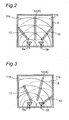
- Fig. 2 is a view of propagation of microwaves in the microwave heating apparatus according to the first embodiment.
- microwaves radiated from the feeding portions 5a and 5b at the two positions are spread radially as radio-wave propagations 11a and 11b indicated by arc-shaped lines. Since microwaves are reflected by the wall surfaces of the heating room 8, the spread of the radio-wave propagations 11a and 11 b is complicated. However, microwaves which reach the object to be heated 10 after being reflected by the wall surfaces of the heating room 8 have reduced electric power, since they propagate longer paths. Therefore, in cases of considering microwave electric power which is absorbed by the object to be heated 10, propagation paths of microwaves which are directly absorbed by the object to be heated 10 from the feeding portions 5a and 5b are dominant.
- the microwave electric powers are substantially summed. Accordingly, if the object to be heated 10 is placed in the same-phase interference area 12(A) formed between the two feeding portions 5a and 5b, the object to be heated 10 is intensively heated, thereby reducing the reflected electric power.
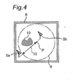
- Fig. 3 is a view of propagation of microwaves in the microwave heating apparatus according to the first embodiment, in cases where microwaves having a phase difference are radiated from the two feeding portions 5a and 5b.
- microwaves having a phase difference which have been radiated are spread radially as indicated by radio-wave propagations 11a and 11b. Due to the phase difference between the microwaves being radiated, the same-phase interference areas 12 in which the radio-wave propagations 11a and 11b overlap with each other at the same phase are shifted from the positions of the same-phase interference areas 12 illustrated in Fig. 2 .
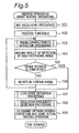
- Fig. 4 is a view of the placement of the feeding portions 5a and 5b in the microwave heating apparatus according to the first embodiment.
- the two feeding portions 5a and 5b are placed on the straight line including the rotational center P of the turntable 9 as the placement table within the heating room 8.
- the feeding portions 5a and 5b are placed under the turntable 9, such that one feeding portion 5a is under the circumferential portion (the outer peripheral side) of the turntable 9, while the other feeding portion 5b is just under the vicinity of the rotational center P (the center side) of the turntable 9. Further, the feeding portions 5a and 5b are placed on the same horizontal surface.
- the motor 13 is driven to cause the turntable 9 to rotate, thereby rotating and moving the object to be heated 10.
- the two feeding portions 5a and 5b are placed within the heating room 8, such that the locus of movement of the object to be heated 10 on the turntable 9 passes through a vertical plane including the straight line 15 connecting the two feeding portions 5a and 5b to each other.
- the range within which the position of the object to be heated 10 can be detected by supplying microwaves from the two feeding portions 5a and 5b with the phase difference being varied as described above is the position on the turntable 9 above the straight line 15 connecting the two feeding portions 5a and 5b to each other. Namely, the range within which the position of the object to be heated 10 can be detected is the position on the turntable 9 vertically above the portion between the feeding portions 5a and 5b.
- the turntable 9 While the turntable 9 is rotated to move the object to be heated 10, the reflected electric powers returning to the two feeding portions 5a and 5b are detected by the electric-power detection portions 6a and 6b, so that the reflected electric powers are reduced when the object to be heated 10 passes above the straight line 15 connecting the feeding portions 5a and 5b to each other (a vertical plane). Based on the phase difference and the rotational position of the turntable 9 of when the reflected electric power has been reduced, it is possible to detect the state of the placement of the object to be heated 10 on the turntable 9.
- the microwave heating apparatus by stopping the turntable 9 at a rotational position which minimizes the electric power reflected to the two feeding portions 5a and 5b, and by detecting the phase difference between the microwaves supplied from the feeding portions 5a and 5b which minimizes the reflected electric power, it is possible to detect the state of the placement of the object to be heated 10 on the turntable 9.
- an oscillating-frequency detection operation for determining the oscillating frequency of the oscillation portion 1 is performed.
- the control portion 7 controls the oscillation portion 1 to detect a frequency characteristic with respect to reflected electric power and extract an oscillating frequency which minimizes the reflected electric power detected by the electric-power detection portions 6a and 6b. Through this extraction operation, an oscillating frequency is determined. Then, an actual heating operation is performed at the determined oscillating frequency.
- control portion 7 operates the oscillation portion 1 until its oscillating frequency reaches from 2400 MHz to an upper limit of 2500 MHz within the frequency variation range, with a 1-MHz pitch, for example, and the control portion 7 determines an oscillating frequency which minimizes the reflected electric power.
- the microwave heating apparatus in the case where a plurality of objects to be heated 10 are placed on the turntable 9, a plurality of minimum values of the reflected electric power are detected, since these objects to be heated 10 pass above the straight line 15 connecting the feeding portions 5a and 5b to each other (a vertical plane). Therefore, based on the number of times that the reflective electric power is minimized, the control portion 7 can detect the number of the objects to be heated 10.
- microwave heating apparatus regarding the state of the placement of the object to be heated 10 on the turntable 9, minimum reflected electric power is detected at intervals of a predetermined rotational angle of the turntable 9, and a desired rotational angle is determined. Further, at this rotational angle, phase characteristics of microwaves which minimize the reflected electric power are detected. Thus, the position of the object to be heated 10 is identified.
- the present invention is not limited to such detection operations. For example, phase-characteristic detection can be also performed at intervals of a predetermined rotational angle of the turntable 9, in order to attain load-state detection operations with higher accuracy.
- phase variation portions 3a and 3b are provided for the respective outputs of the electric-power dividing portion 2, it is possible to change the phase difference, provided that the phase variation portion is connected to any one of the outputs.
- the control portion 7 controls at least the feeding portions 5a and 5b, the phase variation portions 3a and 3b, and the motor 13 serving as the movement mechanism portion, in order to perform microwave heating operations under optimum heating conditions for the object to be heated 10. Note that, according to the heating conditions, the control portion 7 performs control of the oscillating frequency of the oscillation portion 1, and adjustments of the outputs of the amplification portions 4a and 4b.
- microwave heating apparatus has been described with respect to a structural example where the control portion 7 stops the turntable 9 at predetermined rotational-angle intervals and detects the state of the placement of the object to be heated 10 on the turntable 9 above the straight line connecting the two feeding portions 5a and 5b to each other (in a vertical plane), it is also possible to detect the state of the placement of the object to be heated 10 in the state where the turntable 9 is kept rotating. Namely, in the state where the turntable 9 is rotating, an operation for detecting the rotational angle of the turntable 9 and an operation for detecting a phase characteristic can be performed successively and alternately. This results in reduction of the operating time period for the load-state detection operations, thereby enabling reduction of the heating time period.
- the microwave heating apparatus is structured to perform the load-state detection operations for detecting the state of the placement of the object to be heated 10 on the turntable 9 in an initial stage of heating operations and to perform an actual heating operation based on the result of the detection, it is also possible to perform the load-state detection operations (the rotational-angle detection operation and the phase-characteristic detection operation), while performing an actual heating operation according to heating conditions.
- the load-state detection operations the rotational-angle detection operation and the phase-characteristic detection operation
- the microwave heating apparatus according to the first embodiment is capable of accurately detecting the state of the placement of the object to be heated 10 by performing the load-state detection operations. Therefore, the microwave heating apparatus according to the first embodiment is capable of performing, anytime, desired microwave heating on the object to be heated 10 with higher efficiency.
- a microwave heating apparatus according to a second embodiment of the present invention.
- the microwave heating apparatus according to the second embodiment is different from the microwave heating apparatus according to the first embodiment, in terms of load-state detection operations performed by a microwave generating portion, but the basis structure is the same as that of the microwave heating apparatus according to the first embodiment.
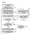
- Figs. 5 to 7 are flow charts illustrating load-state detection operations in the microwave heating apparatus according to the second embodiment.
- the microwave heating apparatus includes a microwave generating portion having the same structure as that of the microwave generating portion in the microwave heating apparatus according to the first embodiment illustrated in Fig. 1 .
- heating operations including load-state detection operations which are performed by the microwave generating portion in the microwave heating apparatus according to the second embodiment.
- Fig. 5 is a flow chart illustrating a main flow illustrating the load-state detection operations. As illustrated in the flow chart in Fig. 5 , heating operations are started, according to the contents of heating settings (a heating start signal) from the manipulation portion.
- heating settings a heating start signal
- step 101 the frequency of the oscillation portion 1 is set to a predetermined oscillating frequency, such as 2450 MHz, and the oscillation portion 1 starts oscillating.
- step 102 positioning of the turntable 9 is performed. Namely, the turntable 9 is set to be at an initial position.
- phase-characteristic detection processing which will be described later is performed.
- microwave electric powers being varied in phase are supplied from the two feeding portions 5a and 5b to the heating room 8, and the reflected electric power is detected.
- step 104 the result of the phase-characteristic detection in the previous stage is recorded.
- step 104 a phase characteristic at each rotational angle of the turntable 9 is recorded.
- step 105 it is determined whether or not the turntable 9 has completed a single rotation and the phase-characteristic detection over the entire placement surface of the turntable 9 has been completed. If the turntable 9 has not yet completed a single rotation, then, in step 106, the turntable 9 is rotated by a certain angle, and the next phase-characteristic detection processing is performed.
- step 107 load-state estimation processing which will be described later is performed. Through the load-state estimation processing, the positions of objects to be heated on the turntable 9, and the number and the size of the objects to be heated are detected.
- steps 101 to 107 described above correspond to the load-state detection operations.
- oscillating-frequency detection processing is processing for detecting an oscillating frequency of the oscillation portion 1 which minimizes the reflected electric power, wherein the detection is performed by sweeping the oscillating frequency of the oscillation portion 1 within the frequency range of 2400 kHz to 2500 kHz.
- the turntable 9 is set to be at an optimum rotational angle, and the phase difference between microwave electric powers is set to be an optimum phase difference.
- step 109 based on the results of the detections through the load-state estimation processing and the frequency detection processing, optimum heating conditions for the object to be heated 10 are determined, and an actual heating operation is started according to the optimum heating conditions.
- Fig. 6 is a flow chart illustrating the phase-characteristic detection processing which is performed in step 103 in the main flow (see Fig. 5 ).
- step 201 the phase difference between the microwave electric powers radiated from the feeding portions 5a and 5b at the two positions is set to 0 degree, as an initial value. Namely, microwave electric powers at the same phase are supplied from the two feeding portions 5a and 5b to the heating room 8, thereby forming a same-phase interference area (see the same-phase interference area 12(A) in Fig. 2 ), at a position midway between the two feeding portions 5a and 5b.
- step 202 the values of the reflected electric powers that the two feeding portions 5a and 5b have received from the heating room 8 are determined.
- step 203 the value of the reflected electric power determined when the phase difference was 0 degree (the initial value) is recorded.
- the determinations of the reflected electric power values in steps 202 and 203 described above are performed by changing the phase difference in steps of a certain value, such as 10 degrees.
- the determination range corresponds to the phase-difference range of 0 to 360 degrees.
- the routine of the determination of the reflected electric power value within the range of 0 to 360 degrees is performed by repeating steps 202 to 205.
- step 204 if the phase difference is determined to be 360 degrees, this phase-characteristic detection processing ends, and the operation proceeds to step 104 illustrated in Fig. 5 .
- Fig. 7 is a flow chart illustrating the load-state estimation processing which is performed in step 107 in the main flow (see Fig. 5 ).
- step 301 a reference is made to the result of the phase-characteristic detection when the rotational angle of the turntable 9 was set to the initial value.
- the threshold value used is a value of the ratio of the reflected electric power to the microwave electric power supplied to the heating room 8. For example, when the ratio is equal to or less than 50 %, the object to be heated 10 which forms a load is determined to exist at a corresponding position.
- the phase-difference range determined in step S302 is recorded as a load position, namely the position of an object to be heated 10 on the turntable 9 (step 303).
- the determination of the presence of a load, and the recording of the load position in steps 302 and 303 are performed until the completion of a single rotation of the turntable 9.
- step 304 it is determined whether or not the rotational angle of the turntable 9 to which a reference is being made indicates the completion of a single rotation.
- step 304 If, in step 304, the rotational angle of the turntable 9 to which a reference is being made does not indicate the completion of a single rotation, the processing proceeds to step 305.
- step 305 it is determined whether or not the load position on the turntable 9 at the previous rotational angle is continuous with the load position on the turntable 9 at the current rotational angle. Namely, it is determined whether or not the phase-difference range within which the reflected electric power value is equal to or less than the threshold value at the previous rotational angle is continuous with the same phase-difference range at the current rotational angle.
- step 305 If it is determined, in step 305, that the load positions are not continuous with each other, then, in step 307, the load position at the current rotational angle is recorded as one indicating the position of another load (an object to be heated).
- step 305 if it is determined, in step 305, that the load positions are continuous with each other, then, in step 306, the load (the object to be heated) detected at the current rotational angle is recorded as the same one as the load (the object to be heated) at the previous rotational angle.
- step 308 a reference is made to the result of the detection of the phase characteristic at the next rotational angle of the turntable 9, and the processing proceeds to step 302.
- step 304 If, in step 304, the rotational angle of the turntable 9 to which a reference is being made indicates the completion of a single rotation, the processing proceeds to step 309.
- step 309 based on the recorded load positions, the ranges of the loads on the turntable 9 are determined, and the state of the placement of the loads (the objects to be heated), namely the positions and the number of the loads, and the sizes of the respective loads, are determined.
- step 310 the number and the positions of the loads (the objects to be heated), and the sizes of the respective loads are confirmed, and the confirmed information is recorded.
- the microwave heating apparatus is capable of determining the state of the placement of objects to be heated 10, namely the positions of the objects to be heated 10 on the turntable 9 and the number and the sizes of the objects to be heated 10, through the load-state detection operations. Therefore, the microwave heating apparatus according to the second embodiment is capable of performing, anytime, desired microwave heating on the objects to be heated 10 with higher efficiency.
- the microwave heating apparatus according to the third embodiment is different from the microwave heating apparatus according to the first embodiment, in terms of the structures of feeding portions and a placement table, and load-state detection operations performed by a microwave generating portion.
- the other portions of the microwave heating apparatus according to the third embodiment have the same basic structures, as those of the microwave heating apparatus according to the first embodiment.
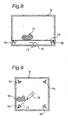
- Fig. 8 is a schematic structural view illustrating the placement table and the feeding portions within a heating room in the microwave heating apparatus according to the third embodiment.
- Fig. 9 is a plan view illustrating the structure of the feeding portions within the heating room in the microwave heating apparatus according to the third embodiment.
- the microwave generating portion in the microwave heating apparatus according to the third embodiment has the same structure as that of the microwave generating portion in the microwave heating apparatus according to the first embodiment illustrated in Fig. 1 .
- the microwave heating apparatus according to the third embodiment includes three or more feeding portions within the heating room, and therefore, the microwave generating portion is provided with a plurality of electric-power dividing portions, a plurality of phase variation portions, a plurality of amplification portions, and a plurality of electric-power detection portions, in association with the number of the feeding portions.
- a shelf 14 as a placement table for objects to be heated 10 is provided within the heating room 8.
- the shelf 14 is placed such that its placement surface forms a horizontal surface, and an object to be heated 10 is placed on the placement surface of the shelf 14.
- the plurality of feeding portions 5a, 5b, 5c and 5d are placed under the shelf 14. These feeding portions 5a, 5b, 5c and 5d are secured to the heating room 8 and will be referred to as fixed feeding portions 5a, 5b, 5c and 5d in the following description. Further, just beneath the center position of the placement surface of the shelf 14, there is provided a rotational feeding portion 16 as a feeding portion as an antenna capable of rotating the direction of radiation in a horizontal plane.
- the feeding portions 5a, 5b, 5c and 5d as four antennas are provided at the four corners of the bottom surface in the heating room 8, in an area under the shelf 14. Further, the rotational feeding portion 16 as a feeding portion as another antenna is placed at a substantially-center position on the bottom surface in the heating room 8.
- the rotational feeding portion 16 is rotatably provided, such that the direction of radiation is oriented toward each of the fixed feeding portions 5a, 5b, 5c and 5d. Namely, the fixed feeding portions 5a, 5b, 5c and 5d are placed at even intervals at positions in a radial shape centered on the rotational feeding portion 16.
- the fixed feeding portions 5a, 5b, 5c and 5d and the rotational feeding portion 16 are placed on a surface substantially parallel with the placement surface of the shelf 14.
- the direction of radiation from the rotational feeding portion 16 is rotated by a motor 13 for combining it with the fixed feeding portion 5a, 5b, 5c or 5d, so that a position 15 of the straight line connecting the feeding portions to each other can be relatively moved with respect to the object to be heated 10 on the shelf 14.
- the motor 13 corresponds to a movement mechanism portion for relatively moving the position of the straight line connecting the rotational feeding portion 16 to the fixed feeding portion 5a, 5b, 5c or 5d to each other with respect to the object to be heated 10 on the shelf 14.
- any one fixed feeding portion is selected from the fixed feeding portions 5a, 5b, 5c and 5d, and the selected fixed feeding portion and the rotational feeding portion 16 at the center are caused to radiate microwave electric power within the heating room 8.
- the microwave heating apparatus is structured to supply microwaves to the rotational feeding portion 16 and any one fixed feeding portion out of the fixed feeding portions 5a, 5b, 5c and 5d, in such a way as to induce an arbitrary phase difference through a phase variation portion, similarly to the structure according to the first embodiment. Further, the reflected electric powers returning to the rotational feeding portion 16 and the fixed feeding portions 5a, 5b, 5c and 5d from the heating room 8 are detected by the electric-power detection portions.
- the rotational feeding portion 16 When the motor 13 is driven, the rotational feeding portion 16 is rotated, which moves the direction of radiation of microwaves. As such, the direction of radiation of microwaves from the rotational feeding portion 16 is moved, which alleviates the heating unevenness in the object to be heated 10 on the shelf 14 placed in the heating room 8.
- the microwave heating apparatus is adapted to perform load-state detection operations similar to the load-state detection operations according to the first embodiment.
- the load-state detection operations according to the third embodiment are performed by rotating the rotational feeding portion 16 at an approximate center of the heating room 8.
- the direction of radiation of microwaves from the rotational feeding portion 16 is set to the direction toward the fixed feeding portion 5a (in a downward and leftward direction in Fig. 9 ), for example, and a phase difference which minimizes the reflected electric power with the combination of the rotational feeding portion 16 and the fixed feeding portion 5a is detected.
- the phase-characteristic detection processing it is possible to detect the state of the placement of the object to be heated 10 above the straight line 15 connecting the two feeding portions 5a and 16 to each other (in a vertical plane).
- the fixed feeding portion 16 is rotated to set the direction of radiation of microwaves to the direction toward another fixed feeding portion 5b (in a downward and rightward direction in Fig. 9 ), for example, and a phase difference which minimizes the reflected electric power with the combination of the rotational feeding portion 16 and the fixed feeding portion 5b is detected.
- the phase-characteristic detection processing it is possible to detect the state of the placement of the object to be heated 10 above the straight line connecting the two feeding portions 5b and 16 to each other (in a vertical plane).
- the rotational feeding portion 16 is successively rotated, and the state of the placement of the object to be heated 10 between the rotational feeding portion 16 and the feeding portion 5c or 5d is detected.
- the microwave heating apparatus is adapted to perform the load-state detection operations, by rotating the direction of radiation of microwaves from the rotational feeding portion 16 at a substantially-center position on the bottom surface in the heating room 8, namely just under the center of the placement surface of the shelf 14, within a plane parallel with the placement surface for the object to be heated 10.
- the load-state detection operations are adapted to successively perform detection of a phase difference which minimizes the reflected electric power, with the combination of the rotational feeding portion 16 and the fixed feeding portion 5a, 5b, 5c or 5d which exists in the direction of radiation from the rotational feeding portion 16.
- the microwave heating apparatus is adapted to perform the phase detection operation and the frequency detection operation which have been described in the first embodiment to determine optimum heating conditions for the object to be heated 10 for performing an actual heating operation.
- the microwave heating apparatus according to the third embodiment is capable of determining the state of the placement of the object to be heated 10, by performing the load-state detection operations. Therefore, the microwave heating apparatus according to the third embodiment is capable of performing, anytime, desired microwave heating on the object to be heated 10 with higher efficiency.
- the rotational feeding portion 16 is provided at a substantially-center position on the bottom surface in the heating room 8, and the fixed feeding portions 5a, 5b, 5c and 5d are provided at the four corners of the bottom surface in the heating room 8, but the fixed feeding portions provided in the heating room 8 are not limited to those at four positions.
- the control portion can start an actual heating operation based on the contents of heating settings having been made through the manipulation portion, and also can perform the load-state detection operations concurrently therewith, in order to determine optimum heating conditions which minimize the reflected electric power. After the optimum heating conditions have been determined, microwave heating operations are performed according to the optimum heating conditions. Accordingly, by performing the load-state detection operations concurrently with actual heating operations, it is possible to shorten heating time periods.
- the microwave heating apparatus is adapted to detect the state of placement of objects to be heated for determining optimum heating conditions, and is adapted to perform microwave heating operations according to the optimum heating conditions. Therefore, the microwave heating apparatus according to the present invention is capable of heating, in desired states, various amounts of various objects to be heated having different shapes and being of different types in shorter time periods, and also is capable of reducing microwave electric power returning to the feeding portions from the heating room, at the same time, thereby enabling microwave heating operations with higher accuracy.
- the microwave heating apparatus according to the present invention is capable of performing microwave heating on various amounts of various objects to be heated having different shapes and being of different types, under optimum heating conditions, by performing load-state detection operations. Therefore, the microwave heating apparatus according to the present invention can also be applied to heating apparatuses which utilize induction heating as represented by microwave ovens, garbage disposers, microwave generators in plasma power supplies serving as semiconductor fabrication apparatuses or other various applications.
Landscapes
- Physics & Mathematics (AREA)
- Electromagnetism (AREA)
- Constitution Of High-Frequency Heating (AREA)
- Control Of High-Frequency Heating Circuits (AREA)
Claims (12)
- Mikrowellenheizvorrichtung, die umfasst:einen Heizraum (8), der ausgelegt ist, ein zu heizendes Objekt (10) aufzunehmen;einen Anordnungstisch (9, 14), der innerhalb des Heizraums (8) vorgesehen ist und eine Anordnungsfläche zum Anordnen des zu heizenden Objekts (10) enthält;einen Schwingungsabschnitt (1), der ausgelegt ist, elektrische Mikrowellenleistung zu erzeugen;einen Abschnitt zum Aufteilen der elektrischen Leistung (2), der ausgelegt ist, eine Ausgabe des Schwingungsabschnitts (1) in mehrere Teile aufzuteilen;mehrere Zuführabschnitte (5a bis 5d), die auf einer Wandfläche in dem Heizraum (8) positioniert sind und ausgelegt sind, jeweilige Ausgaben des Abschnitts zum Aufteilen der elektrischen Leistung (2) dem Heizraum (8) zuzuführen;einen Phasenvariationsabschnitt (3a, 3b), der in einem Übertragungsweg zwischen dem Abschnitt zum Aufteilen der elektrischen Leistung (2) und den Zuführabschnitten (5a bis 5d) vorgesehen ist und ausgelegt ist, die Phase mindestens einer der Ausgaben des Abschnitts zum Aufteilen der elektrischen Leistung (2) zu variieren;mehrere Abschnitte zum Detektieren der elektrischen Leistung (6a, 6b), die ausgelegt sind, reflektierte elektrische Leistung, die von dem Heizraum (8) zu den Zuführabschnitten (5qa bis 5d) zurückkehrt, zu detektieren;einen Steuerabschnitt (7), der ausgelegt ist, eine Schwingungsfrequenz des Schwingungsabschnitts (1) und die Ausgangsphase des Phasenvariationsabschnitts (3a, 3b) zu steuern;gekennzeichnet durch:einen Bewegungsmechanismusabschnitt (13), der ausgelegt ist, eine Position einer geraden Linie (15), die jeweils zwei Zuführabschnitte (5a bis 5d) von den mehreren Zuführabschnitten (5a bis 5d) verbindet, in Bezug auf das zu heizende Objekt (10) auf dem Anordnungstisch (9, 14) zu bewegen;wobei der Steuerabschnitt (7) ferner ausgelegt ist:die Position, zu der sich der Bewegungsmechanismusabschnitt (13) bewegt, zu steuern,die Position der geraden Linie (15), die die beiden Zuführabschnitte (5a bis 5d) miteinander verbindet, durch den Bewegungsmechanismusabschnitt (13) in Bezug auf das zu heizende Objekt (10) zu bewegen,durch den Phasenvariationsabschnitt (3a, 3b) gesteuerte elektrische Mikrowellenleistung durch die beiden Zuführabschnitte (5a bis 5d) dem Heizraum (8) zuzuführen undeinen Phasenunterschied zwischen den elektrischen Mikrowellenleistungen, der die von dem Heizraum (8) zu den beiden Zuführabschnitten (5a bis 5d) zurückkehrende reflektierte elektrische Leistung minimiert, zu detektieren, um einen Zustand der Anordnung des zu heizenden Objekts (10) auf dem Anordnungstisch (9, 14) zu detektieren.
- Mikrowellenheizvorrichtung nach Anspruch 1, wobei
der Steuerabschnitt (7) ausgelegt ist, elektrische Mikrowellenleistungen mit einem Phasenunterschied durch die beiden Zuführabschnitte (5a bis 5d) dem Heizraum (8) zuzuführen, und ausgelegt ist, einen Phasenunterschied zu detektieren, der die von dem Heizraum (8) zu den beiden Zuführabschnitten (5a bis 5d) zurückkehrende reflektierte elektrische Leistung minimiert, um den Zustand der Anordnung des zu heizenden Objekts (10) auf dem Anordnungstisch (9, 14) in einer vertikalen Ebene, die die gerade Linie (15) enthält, die die beiden Zuführabschnitte (5a bis 5d) miteinander verbindet, zu detektieren. - Mikrowellenheizvorrichtung nach Anspruch 2, wobei
der Steuerabschnitt (7) ausgelegt ist, mindestens die Zuführabschnitte (5a bis 5d), den Phasenvariationsabschnitt (3a, 3b) und den Bewegungsmechanismusabschnitt (13) aufgrund des detektierten Zustands der Anordnung des zu heizenden Objekts (10) auf dem Anordnungstisch (9, 14) zu steuern. - Mikrowellenheizvorrichtung nach Anspruch 3, wobei
der Anordnungstisch (9, 14) ausgelegt ist, drehbar zu sein, und derart ausgelegt ist, dass das zu heizende Objekt (10) auf dem Anordnungstisch (9, 14) durch die vertikale Ebene, die die gerade Linie (15) enthält, die die beiden Zuführabschnitte (5a bis 5d) miteinander verbindet, hindurchführt, wenn der Anordnungstisch (9, 14) durch den Bewegungsmechanismusabschnitt (13) gedreht wird. - Mikrowellenheizvorrichtung nach Anspruch 4, wobei
einer der beiden Zuführabschnitte in der Nähe eines äußeren Umfangs des Anordnungstischs (9, 14) positioniert ist, während der andere Zuführabschnitt in der Nähe eines Mittelpunkts des Anordnungstischs (9, 14) positioniert ist. - Mikrowellenheizvorrichtung nach Anspruch 3, wobei
mindestens ein einzelner Zuführabschnitt einen Drehzuführabschnitt (16) der mehreren Zuführabschnitte (5a bis 5d) umfasst, der an den Bewegungsmechanismusabschnitt (13) derart gekoppelt ist, dass eine Richtung der Strahlung drehbar ist, während die anderen Zuführabschnitte (5a bis 5d) feste Zuführabschnitte umfassen, die so positioniert sind, dass sie der Richtung der Strahlung von dem Drehzuführabschnitt (16) zugewandt sind, und
ein Zuführabschnitt der beiden Zuführabschnitte (5a bis 5d), die mit elektrischer Mikrowellenleistung versorgt werden, den Drehzuführabschnitt (16) bildet. - Mikrowellenheizvorrichtung nach Anspruch 5, wobei
der Steuerabschnitt (7) ausgelegt ist, eine Position, eine Nummer und eine Größe des zu heizenden Objekts (10) auf dem Anordnungstisch (9, 14) in der vertikalen Ebene, die die gerade Linie (15) enthält, die die beiden Zuführabschnitte (5a bis 5d) miteinander verbindet, durch Bewirken, dass der Bewegungsmechanismus (13) die Drehung des Anordnungstischs (9, 14) anhält, zu detektieren. - Mikrowellenheizvorrichtung nach Anspruch 5, wobei
der Steuerabschnitt (7) ausgelegt ist, die Position, die Nummer und die Größe des zu heizenden Objekts (10) auf dem Anordnungstisch (9, 14) in der vertikalen Ebene, die die gerade Linie (15) enthält, die die beiden Zuführabschnitte (5a bis 5d) miteinander verbindet, zu detektieren, während bewirkt wird, dass der Bewegungsmechanismus (13) fortfährt, den Anordnungstisch (9, 14) zu drehen. - Mikrowellenheizvorrichtung nach Anspruch 3, wobei
der Steuerabschnitt (7) ausgelegt ist, den Zustand der Anordnung des zu heizenden Objekts (10) auf dem Anordnungstisch (9, 14) in einem Anfangszustand in einem Heizvorgang zu detektieren und mindestens die Zuführabschnitte (5a bis 5d), den Phasenvariationsabschnitt (3a, 3b) und den Bewegungsmechanismusabschnitt (13) zu steuern, und ausgelegt ist, danach einen tatsächlichen Heizvorgang auszuführen. - Mikrowellenheizvorrichtung nach Anspruch 6, wobei
der Steuerabschnitt (7) ausgelegt ist, jeweilige elektrische Mikrowellenleistungen mit einer gesteuerten Phasendifferenz dem Drehzuführabschnitt (16) und den festen Zuführabschnitten (5a bis 5d), die so positioniert sind, dass sie der Richtung der Strahlung von dem Drehzuführabschnitt (16) zugewandt sind, zuzuführen, und ausgelegt ist, den Zustand der Anordnung des zu heizenden Objekts (10) auf dem Anordnungstisch (9, 14) in der vertikalen Ebene, die die gerade Linie (15) enthält, die den Drehzuführabschnitt (16) und die festen Zuführabschnitte (5a bis 5d), denen die elektrischen Mikrowellenleistungen zugeführt wurden, miteinander verbindet, zu detektieren. - Mikrowellenheizvorrichtung nach Anspruch 6, wobei
die festen Zuführabschnitte (5a bis 5d) in gleichmäßigen Abständen an Positionen in einer radialen Form, die um den Drehzuführabschnitt (16) zentriert sind, positioniert sind und
der Steuerabschnitt (7) ausgelegt ist, den Zustand der Anordnung des zu heizenden Objekts (10) auf dem Anordnungstisch (9, 14) durch Drehen der Richtung der Strahlung von dem Drehzuführabschnitt (16) zu detektieren. - Mikrowellenheizvorrichtung nach Anspruch 11, wobei
der Steuerabschnitt (7) ausgelegt ist, den Zustand der Anordnung des zu heizenden Objekts (10) auf dem Anordnungstisch (9, 14) durch aufeinanderfolgendes Anhalten der Richtung der Strahlung von dem Drehzuführabschnitt (16) an Positionen, an denen die Richtung der Strahlung den festen Zuführabschnitten (5a bis 5d) zugewandt ist, zu detektieren.
Applications Claiming Priority (2)
| Application Number | Priority Date | Filing Date | Title |
|---|---|---|---|
| JP2010063818 | 2010-03-19 | ||
| PCT/JP2011/001505 WO2011114711A1 (ja) | 2010-03-19 | 2011-03-15 | マイクロ波加熱装置 |
Publications (3)
| Publication Number | Publication Date |
|---|---|
| EP2549832A1 EP2549832A1 (de) | 2013-01-23 |
| EP2549832A4 EP2549832A4 (de) | 2014-11-05 |
| EP2549832B1 true EP2549832B1 (de) | 2015-12-30 |
Family
ID=44648823
Family Applications (1)
| Application Number | Title | Priority Date | Filing Date |
|---|---|---|---|
| EP11755902.1A Not-in-force EP2549832B1 (de) | 2010-03-19 | 2011-03-15 | Mirkowellenerhitzungsvorrichtung |
Country Status (5)
| Country | Link |
|---|---|
| US (1) | US9029744B2 (de) |
| EP (1) | EP2549832B1 (de) |
| JP (1) | JP5830687B2 (de) |
| CN (1) | CN102804914A (de) |
| WO (1) | WO2011114711A1 (de) |
Families Citing this family (9)
| Publication number | Priority date | Publication date | Assignee | Title |
|---|---|---|---|---|
| ES2448216T3 (es) | 2008-11-10 | 2014-03-13 | Goji Limited | Dispositivo y método de calentamiento mediante el uso de energía de radiofrecuencia (RF) |
| JP5657016B2 (ja) * | 2009-11-10 | 2015-01-21 | ゴジ リミテッド | エネルギーを制御するための装置および方法 |
| WO2011149275A2 (en) * | 2010-05-26 | 2011-12-01 | Lg Electronics Inc. | Cooking apparatus |
| EP2953425B1 (de) | 2014-06-03 | 2019-08-21 | Ampleon Netherlands B.V. | Radiofrequenz-Erwärmungsvorrichtung |
| KR102402039B1 (ko) | 2015-11-16 | 2022-05-26 | 삼성전자주식회사 | 조리 장치 및 이의 제어 방법 |
| US20180323091A1 (en) * | 2017-05-03 | 2018-11-08 | Applied Materials, Inc. | Method and apparatus for uniform thermal distribution in a microwave cavity during semiconductor processing |
| CN111031622B (zh) * | 2019-12-30 | 2022-02-25 | 广东美的厨房电器制造有限公司 | 微波加热组件、微波加热设备和控制方法 |
| CN110996422B (zh) * | 2019-12-30 | 2022-02-01 | 广东美的厨房电器制造有限公司 | 微波加热组件、微波加热设备和控制方法 |
| CN115978913A (zh) * | 2022-12-19 | 2023-04-18 | 上海艾录包装股份有限公司 | 一种微波真空低温干燥机及工艺 |
Family Cites Families (13)
| Publication number | Priority date | Publication date | Assignee | Title |
|---|---|---|---|---|
| JPS5696486A (en) | 1979-12-28 | 1981-08-04 | Matsushita Electric Industrial Co Ltd | High frequency heater |
| JPS56132793A (en) | 1980-03-19 | 1981-10-17 | Hitachi Netsu Kigu Kk | High frequency heater |
| JPS59134593A (ja) | 1983-01-20 | 1984-08-02 | 松下電器産業株式会社 | 高周波加熱装置 |
| JPS59165399A (ja) | 1983-03-09 | 1984-09-18 | 株式会社東芝 | 高周波加熱装置 |
| JPS6248354A (ja) | 1985-08-28 | 1987-03-03 | Fujiwara Jiyouki Sangyo Kk | 諸味粕剥装置における粕濾布自動供給装置 |
| JP2006128075A (ja) * | 2004-10-01 | 2006-05-18 | Seiko Epson Corp | 高周波加熱装置、半導体製造装置および光源装置 |
| KR20060079814A (ko) * | 2005-01-03 | 2006-07-06 | 삼성전자주식회사 | 전자레인지의 조리제어장치 및 그 방법 |
| JP2007024388A (ja) * | 2005-07-15 | 2007-02-01 | Matsushita Electric Ind Co Ltd | 加熱調理装置 |
| JP5064924B2 (ja) * | 2006-08-08 | 2012-10-31 | パナソニック株式会社 | マイクロ波処理装置 |
| JP5104048B2 (ja) * | 2007-06-12 | 2012-12-19 | パナソニック株式会社 | マイクロ波処理装置 |
| JP5169255B2 (ja) | 2008-01-29 | 2013-03-27 | パナソニック株式会社 | マイクロ波処理装置 |
| JP5169371B2 (ja) | 2008-03-26 | 2013-03-27 | パナソニック株式会社 | マイクロ波処理装置 |
| US8610038B2 (en) * | 2008-06-30 | 2013-12-17 | The Invention Science Fund I, Llc | Microwave oven |
-
2011
- 2011-03-15 EP EP11755902.1A patent/EP2549832B1/de not_active Not-in-force
- 2011-03-15 CN CN2011800144572A patent/CN102804914A/zh active Pending
- 2011-03-15 JP JP2012505508A patent/JP5830687B2/ja not_active Expired - Fee Related
- 2011-03-15 US US13/635,864 patent/US9029744B2/en active Active
- 2011-03-15 WO PCT/JP2011/001505 patent/WO2011114711A1/ja not_active Ceased
Also Published As
| Publication number | Publication date |
|---|---|
| EP2549832A1 (de) | 2013-01-23 |
| US20130008896A1 (en) | 2013-01-10 |
| JPWO2011114711A1 (ja) | 2013-06-27 |
| US9029744B2 (en) | 2015-05-12 |
| WO2011114711A1 (ja) | 2011-09-22 |
| JP5830687B2 (ja) | 2015-12-09 |
| CN102804914A (zh) | 2012-11-28 |
| EP2549832A4 (de) | 2014-11-05 |
Similar Documents
| Publication | Publication Date | Title |
|---|---|---|
| US9029744B2 (en) | Microwave heating apparatus | |
| EP2475221B1 (de) | Mikrowellenheizvorrichtung | |
| US9398644B2 (en) | Radio-frequency heating apparatus and radio-frequency heating method | |
| US10667337B2 (en) | Method of control of a multifeed radio frequency device | |
| EP3437433B1 (de) | Mikrowellenheizvorrichtung und verfahren zum betrieb einer mikrowellenheizvorrichtung | |
| CN101860996B (zh) | 具有使用场传感器的调节系统的微波炉 | |
| EP3120665B1 (de) | Röhrenlose mikrowellenvorrichtung | |
| US11013073B2 (en) | System for preparing and method for operating a system for preparing at least one food | |
| US20100224623A1 (en) | Microwave heating apparatus | |
| EP2704525B1 (de) | Mikrowellenofen | |
| CN109792810A (zh) | 利用效率的变化系数检测食物负载特性变化的系统和方法 | |
| CN109156052B (zh) | 微波加热装置以及用于操作微波加热装置的方法 | |
| JP2009252346A (ja) | マイクロ波処理装置 | |
| EP3560289B1 (de) | Verfahren, system und vorrichtung zur bereitstellung von elektromagnetischer hochfrequenzenergie | |
| US20240032161A1 (en) | Intelligent microwave cooking system | |
| EP4326002A1 (de) | Hochfrequenzheizvorrichtung | |
| JP2009181728A (ja) | マイクロ波処理装置 | |
| KR20190116016A (ko) | 주파수 스캔 및 가열 알고리즘이 개선된 마이크로파 가열 장치 | |
| JP4836965B2 (ja) | 高周波加熱装置 | |
| JP5444734B2 (ja) | マイクロ波処理装置 | |
| US10827569B2 (en) | Crispness and browning in full flat microwave oven | |
| KR0138606B1 (ko) | 전자렌지의 조리제어장치 및 그 방법 | |
| KR20090087569A (ko) | 전자레인지 및 그 제어방법 | |
| KR0160421B1 (ko) | 전자렌지의 균등가열제어장치 및 방법 | |
| JP2010255872A (ja) | 加熱調理器 |
Legal Events
| Date | Code | Title | Description |
|---|---|---|---|
| PUAI | Public reference made under article 153(3) epc to a published international application that has entered the european phase |
Free format text: ORIGINAL CODE: 0009012 |
|
| 17P | Request for examination filed |
Effective date: 20120910 |
|
| AK | Designated contracting states |
Kind code of ref document: A1 Designated state(s): AL AT BE BG CH CY CZ DE DK EE ES FI FR GB GR HR HU IE IS IT LI LT LU LV MC MK MT NL NO PL PT RO RS SE SI SK SM TR |
|
| DAX | Request for extension of the european patent (deleted) | ||
| A4 | Supplementary search report drawn up and despatched |
Effective date: 20141008 |
|
| RIC1 | Information provided on ipc code assigned before grant |
Ipc: H05B 6/64 20060101AFI20141001BHEP Ipc: H05B 6/72 20060101ALI20141001BHEP Ipc: H05B 6/68 20060101ALI20141001BHEP Ipc: H05B 6/70 20060101ALI20141001BHEP |
|
| GRAP | Despatch of communication of intention to grant a patent |
Free format text: ORIGINAL CODE: EPIDOSNIGR1 |
|
| GRAJ | Information related to disapproval of communication of intention to grant by the applicant or resumption of examination proceedings by the epo deleted |
Free format text: ORIGINAL CODE: EPIDOSDIGR1 |
|
| GRAP | Despatch of communication of intention to grant a patent |
Free format text: ORIGINAL CODE: EPIDOSNIGR1 |
|
| INTG | Intention to grant announced |
Effective date: 20150709 |
|
| INTG | Intention to grant announced |
Effective date: 20150720 |
|
| GRAS | Grant fee paid |
Free format text: ORIGINAL CODE: EPIDOSNIGR3 |
|
| GRAA | (expected) grant |
Free format text: ORIGINAL CODE: 0009210 |
|
| AK | Designated contracting states |
Kind code of ref document: B1 Designated state(s): AL AT BE BG CH CY CZ DE DK EE ES FI FR GB GR HR HU IE IS IT LI LT LU LV MC MK MT NL NO PL PT RO RS SE SI SK SM TR |
|
| REG | Reference to a national code |
Ref country code: GB Ref legal event code: FG4D |
|
| REG | Reference to a national code |
Ref country code: CH Ref legal event code: EP |
|
| REG | Reference to a national code |
Ref country code: AT Ref legal event code: REF Ref document number: 767973 Country of ref document: AT Kind code of ref document: T Effective date: 20160115 |
|
| REG | Reference to a national code |
Ref country code: IE Ref legal event code: FG4D |
|
| REG | Reference to a national code |
Ref country code: DE Ref legal event code: R096 Ref document number: 602011022278 Country of ref document: DE |
|
| REG | Reference to a national code |
Ref country code: LT Ref legal event code: MG4D |
|
| PG25 | Lapsed in a contracting state [announced via postgrant information from national office to epo] |
Ref country code: LT Free format text: LAPSE BECAUSE OF FAILURE TO SUBMIT A TRANSLATION OF THE DESCRIPTION OR TO PAY THE FEE WITHIN THE PRESCRIBED TIME-LIMIT Effective date: 20151230 Ref country code: NO Free format text: LAPSE BECAUSE OF FAILURE TO SUBMIT A TRANSLATION OF THE DESCRIPTION OR TO PAY THE FEE WITHIN THE PRESCRIBED TIME-LIMIT Effective date: 20160330 Ref country code: HR Free format text: LAPSE BECAUSE OF FAILURE TO SUBMIT A TRANSLATION OF THE DESCRIPTION OR TO PAY THE FEE WITHIN THE PRESCRIBED TIME-LIMIT Effective date: 20151230 |
|
| REG | Reference to a national code |
Ref country code: NL Ref legal event code: MP Effective date: 20151230 |
|
| REG | Reference to a national code |
Ref country code: AT Ref legal event code: MK05 Ref document number: 767973 Country of ref document: AT Kind code of ref document: T Effective date: 20151230 |
|
| PG25 | Lapsed in a contracting state [announced via postgrant information from national office to epo] |
Ref country code: GR Free format text: LAPSE BECAUSE OF FAILURE TO SUBMIT A TRANSLATION OF THE DESCRIPTION OR TO PAY THE FEE WITHIN THE PRESCRIBED TIME-LIMIT Effective date: 20160331 Ref country code: FI Free format text: LAPSE BECAUSE OF FAILURE TO SUBMIT A TRANSLATION OF THE DESCRIPTION OR TO PAY THE FEE WITHIN THE PRESCRIBED TIME-LIMIT Effective date: 20151230 Ref country code: SE Free format text: LAPSE BECAUSE OF FAILURE TO SUBMIT A TRANSLATION OF THE DESCRIPTION OR TO PAY THE FEE WITHIN THE PRESCRIBED TIME-LIMIT Effective date: 20151230 Ref country code: LV Free format text: LAPSE BECAUSE OF FAILURE TO SUBMIT A TRANSLATION OF THE DESCRIPTION OR TO PAY THE FEE WITHIN THE PRESCRIBED TIME-LIMIT Effective date: 20151230 Ref country code: RS Free format text: LAPSE BECAUSE OF FAILURE TO SUBMIT A TRANSLATION OF THE DESCRIPTION OR TO PAY THE FEE WITHIN THE PRESCRIBED TIME-LIMIT Effective date: 20151230 |
|
| PG25 | Lapsed in a contracting state [announced via postgrant information from national office to epo] |
Ref country code: NL Free format text: LAPSE BECAUSE OF FAILURE TO SUBMIT A TRANSLATION OF THE DESCRIPTION OR TO PAY THE FEE WITHIN THE PRESCRIBED TIME-LIMIT Effective date: 20151230 |
|
| PG25 | Lapsed in a contracting state [announced via postgrant information from national office to epo] |
Ref country code: CZ Free format text: LAPSE BECAUSE OF FAILURE TO SUBMIT A TRANSLATION OF THE DESCRIPTION OR TO PAY THE FEE WITHIN THE PRESCRIBED TIME-LIMIT Effective date: 20151230 Ref country code: IT Free format text: LAPSE BECAUSE OF FAILURE TO SUBMIT A TRANSLATION OF THE DESCRIPTION OR TO PAY THE FEE WITHIN THE PRESCRIBED TIME-LIMIT Effective date: 20151230 Ref country code: ES Free format text: LAPSE BECAUSE OF FAILURE TO SUBMIT A TRANSLATION OF THE DESCRIPTION OR TO PAY THE FEE WITHIN THE PRESCRIBED TIME-LIMIT Effective date: 20151230 |
|
| PGFP | Annual fee paid to national office [announced via postgrant information from national office to epo] |
Ref country code: DE Payment date: 20160330 Year of fee payment: 6 |
|
| PG25 | Lapsed in a contracting state [announced via postgrant information from national office to epo] |
Ref country code: SM Free format text: LAPSE BECAUSE OF FAILURE TO SUBMIT A TRANSLATION OF THE DESCRIPTION OR TO PAY THE FEE WITHIN THE PRESCRIBED TIME-LIMIT Effective date: 20151230 Ref country code: IS Free format text: LAPSE BECAUSE OF FAILURE TO SUBMIT A TRANSLATION OF THE DESCRIPTION OR TO PAY THE FEE WITHIN THE PRESCRIBED TIME-LIMIT Effective date: 20160430 Ref country code: PT Free format text: LAPSE BECAUSE OF FAILURE TO SUBMIT A TRANSLATION OF THE DESCRIPTION OR TO PAY THE FEE WITHIN THE PRESCRIBED TIME-LIMIT Effective date: 20160502 Ref country code: BE Free format text: LAPSE BECAUSE OF NON-PAYMENT OF DUE FEES Effective date: 20160331 Ref country code: AT Free format text: LAPSE BECAUSE OF FAILURE TO SUBMIT A TRANSLATION OF THE DESCRIPTION OR TO PAY THE FEE WITHIN THE PRESCRIBED TIME-LIMIT Effective date: 20151230 Ref country code: RO Free format text: LAPSE BECAUSE OF FAILURE TO SUBMIT A TRANSLATION OF THE DESCRIPTION OR TO PAY THE FEE WITHIN THE PRESCRIBED TIME-LIMIT Effective date: 20151230 Ref country code: PL Free format text: LAPSE BECAUSE OF FAILURE TO SUBMIT A TRANSLATION OF THE DESCRIPTION OR TO PAY THE FEE WITHIN THE PRESCRIBED TIME-LIMIT Effective date: 20151230 Ref country code: EE Free format text: LAPSE BECAUSE OF FAILURE TO SUBMIT A TRANSLATION OF THE DESCRIPTION OR TO PAY THE FEE WITHIN THE PRESCRIBED TIME-LIMIT Effective date: 20151230 Ref country code: SK Free format text: LAPSE BECAUSE OF FAILURE TO SUBMIT A TRANSLATION OF THE DESCRIPTION OR TO PAY THE FEE WITHIN THE PRESCRIBED TIME-LIMIT Effective date: 20151230 |
|
| REG | Reference to a national code |
Ref country code: DE Ref legal event code: R097 Ref document number: 602011022278 Country of ref document: DE |
|
| PG25 | Lapsed in a contracting state [announced via postgrant information from national office to epo] |
Ref country code: DK Free format text: LAPSE BECAUSE OF FAILURE TO SUBMIT A TRANSLATION OF THE DESCRIPTION OR TO PAY THE FEE WITHIN THE PRESCRIBED TIME-LIMIT Effective date: 20151230 Ref country code: MC Free format text: LAPSE BECAUSE OF FAILURE TO SUBMIT A TRANSLATION OF THE DESCRIPTION OR TO PAY THE FEE WITHIN THE PRESCRIBED TIME-LIMIT Effective date: 20151230 Ref country code: LU Free format text: LAPSE BECAUSE OF FAILURE TO SUBMIT A TRANSLATION OF THE DESCRIPTION OR TO PAY THE FEE WITHIN THE PRESCRIBED TIME-LIMIT Effective date: 20160315 |
|
| REG | Reference to a national code |
Ref country code: CH Ref legal event code: PL |
|
| PLBE | No opposition filed within time limit |
Free format text: ORIGINAL CODE: 0009261 |
|
| STAA | Information on the status of an ep patent application or granted ep patent |
Free format text: STATUS: NO OPPOSITION FILED WITHIN TIME LIMIT |
|
| GBPC | Gb: european patent ceased through non-payment of renewal fee |
Effective date: 20160330 |
|
| 26N | No opposition filed |
Effective date: 20161003 |
|
| REG | Reference to a national code |
Ref country code: IE Ref legal event code: MM4A |
|
| PG25 | Lapsed in a contracting state [announced via postgrant information from national office to epo] |
Ref country code: BE Free format text: LAPSE BECAUSE OF FAILURE TO SUBMIT A TRANSLATION OF THE DESCRIPTION OR TO PAY THE FEE WITHIN THE PRESCRIBED TIME-LIMIT Effective date: 20151230 |
|
| REG | Reference to a national code |
Ref country code: FR Ref legal event code: ST Effective date: 20161130 |
|
| PG25 | Lapsed in a contracting state [announced via postgrant information from national office to epo] |
Ref country code: IE Free format text: LAPSE BECAUSE OF NON-PAYMENT OF DUE FEES Effective date: 20160315 Ref country code: FR Free format text: LAPSE BECAUSE OF NON-PAYMENT OF DUE FEES Effective date: 20160331 Ref country code: LI Free format text: LAPSE BECAUSE OF NON-PAYMENT OF DUE FEES Effective date: 20160331 Ref country code: CH Free format text: LAPSE BECAUSE OF NON-PAYMENT OF DUE FEES Effective date: 20160331 Ref country code: GB Free format text: LAPSE BECAUSE OF NON-PAYMENT OF DUE FEES Effective date: 20160330 |
|
| PG25 | Lapsed in a contracting state [announced via postgrant information from national office to epo] |
Ref country code: SI Free format text: LAPSE BECAUSE OF FAILURE TO SUBMIT A TRANSLATION OF THE DESCRIPTION OR TO PAY THE FEE WITHIN THE PRESCRIBED TIME-LIMIT Effective date: 20151230 |
|
| PG25 | Lapsed in a contracting state [announced via postgrant information from national office to epo] |
Ref country code: MT Free format text: LAPSE BECAUSE OF FAILURE TO SUBMIT A TRANSLATION OF THE DESCRIPTION OR TO PAY THE FEE WITHIN THE PRESCRIBED TIME-LIMIT Effective date: 20151230 |
|
| REG | Reference to a national code |
Ref country code: DE Ref legal event code: R119 Ref document number: 602011022278 Country of ref document: DE |
|
| PG25 | Lapsed in a contracting state [announced via postgrant information from national office to epo] |
Ref country code: DE Free format text: LAPSE BECAUSE OF NON-PAYMENT OF DUE FEES Effective date: 20171003 |
|
| PG25 | Lapsed in a contracting state [announced via postgrant information from national office to epo] |
Ref country code: CY Free format text: LAPSE BECAUSE OF FAILURE TO SUBMIT A TRANSLATION OF THE DESCRIPTION OR TO PAY THE FEE WITHIN THE PRESCRIBED TIME-LIMIT Effective date: 20151230 Ref country code: HU Free format text: LAPSE BECAUSE OF FAILURE TO SUBMIT A TRANSLATION OF THE DESCRIPTION OR TO PAY THE FEE WITHIN THE PRESCRIBED TIME-LIMIT; INVALID AB INITIO Effective date: 20110315 |
|
| PG25 | Lapsed in a contracting state [announced via postgrant information from national office to epo] |
Ref country code: MK Free format text: LAPSE BECAUSE OF FAILURE TO SUBMIT A TRANSLATION OF THE DESCRIPTION OR TO PAY THE FEE WITHIN THE PRESCRIBED TIME-LIMIT Effective date: 20151230 Ref country code: TR Free format text: LAPSE BECAUSE OF FAILURE TO SUBMIT A TRANSLATION OF THE DESCRIPTION OR TO PAY THE FEE WITHIN THE PRESCRIBED TIME-LIMIT Effective date: 20151230 Ref country code: MT Free format text: LAPSE BECAUSE OF FAILURE TO SUBMIT A TRANSLATION OF THE DESCRIPTION OR TO PAY THE FEE WITHIN THE PRESCRIBED TIME-LIMIT Effective date: 20160331 |
|
| PG25 | Lapsed in a contracting state [announced via postgrant information from national office to epo] |
Ref country code: BG Free format text: LAPSE BECAUSE OF FAILURE TO SUBMIT A TRANSLATION OF THE DESCRIPTION OR TO PAY THE FEE WITHIN THE PRESCRIBED TIME-LIMIT Effective date: 20151230 |
|
| PG25 | Lapsed in a contracting state [announced via postgrant information from national office to epo] |
Ref country code: AL Free format text: LAPSE BECAUSE OF FAILURE TO SUBMIT A TRANSLATION OF THE DESCRIPTION OR TO PAY THE FEE WITHIN THE PRESCRIBED TIME-LIMIT Effective date: 20151230 |