EP2550062B1 - Procédés pour faire fonctionner un dispositif d'irradiation - Google Patents
Procédés pour faire fonctionner un dispositif d'irradiation Download PDFInfo
- Publication number
- EP2550062B1 EP2550062B1 EP11710690.6A EP11710690A EP2550062B1 EP 2550062 B1 EP2550062 B1 EP 2550062B1 EP 11710690 A EP11710690 A EP 11710690A EP 2550062 B1 EP2550062 B1 EP 2550062B1
- Authority
- EP
- European Patent Office
- Prior art keywords
- irradiation
- target volume
- control input
- target
- volume region
- Prior art date
- Legal status (The legal status is an assumption and is not a legal conclusion. Google has not performed a legal analysis and makes no representation as to the accuracy of the status listed.)
- Not-in-force
Links
- 238000000034 method Methods 0.000 title claims description 77
- 230000005855 radiation Effects 0.000 title claims description 25
- 239000002245 particle Substances 0.000 claims description 85
- 230000033001 locomotion Effects 0.000 claims description 54
- 238000012937 correction Methods 0.000 claims description 25
- 239000000463 material Substances 0.000 claims description 17
- 239000013598 vector Substances 0.000 claims description 17
- 230000000694 effects Effects 0.000 claims description 14
- 238000004422 calculation algorithm Methods 0.000 claims description 10
- 238000013213 extrapolation Methods 0.000 claims description 10
- 230000002123 temporal effect Effects 0.000 claims description 10
- 230000001678 irradiating effect Effects 0.000 claims description 8
- 230000006978 adaptation Effects 0.000 claims description 6
- 230000004044 response Effects 0.000 claims description 6
- 230000003750 conditioning effect Effects 0.000 claims description 3
- 238000013528 artificial neural network Methods 0.000 claims description 2
- 238000000605 extraction Methods 0.000 description 20
- 150000002500 ions Chemical class 0.000 description 12
- 210000001519 tissue Anatomy 0.000 description 12
- 230000004907 flux Effects 0.000 description 10
- 230000008859 change Effects 0.000 description 9
- 230000001934 delay Effects 0.000 description 9
- 206010028980 Neoplasm Diseases 0.000 description 7
- 230000008569 process Effects 0.000 description 7
- 238000004364 calculation method Methods 0.000 description 6
- 238000005516 engineering process Methods 0.000 description 6
- 230000000241 respiratory effect Effects 0.000 description 6
- 230000008901 benefit Effects 0.000 description 5
- 238000001228 spectrum Methods 0.000 description 5
- -1 Helium ions Chemical class 0.000 description 4
- 230000004071 biological effect Effects 0.000 description 4
- 238000011161 development Methods 0.000 description 4
- 230000018109 developmental process Effects 0.000 description 4
- 238000009826 distribution Methods 0.000 description 4
- 239000011358 absorbing material Substances 0.000 description 3
- 238000003384 imaging method Methods 0.000 description 3
- 238000005259 measurement Methods 0.000 description 3
- 241000920340 Pion Species 0.000 description 2
- 238000013459 approach Methods 0.000 description 2
- 210000004204 blood vessel Anatomy 0.000 description 2
- 229910052799 carbon Inorganic materials 0.000 description 2
- 125000004122 cyclic group Chemical group 0.000 description 2
- 230000006378 damage Effects 0.000 description 2
- 238000010586 diagram Methods 0.000 description 2
- 238000006073 displacement reaction Methods 0.000 description 2
- 235000013305 food Nutrition 0.000 description 2
- 238000004519 manufacturing process Methods 0.000 description 2
- 239000011159 matrix material Substances 0.000 description 2
- 238000005457 optimization Methods 0.000 description 2
- 238000002360 preparation method Methods 0.000 description 2
- 238000001959 radiotherapy Methods 0.000 description 2
- 230000002105 relative biological effectiveness Effects 0.000 description 2
- 238000003860 storage Methods 0.000 description 2
- 238000002560 therapeutic procedure Methods 0.000 description 2
- OKTJSMMVPCPJKN-UHFFFAOYSA-N Carbon Chemical compound [C] OKTJSMMVPCPJKN-UHFFFAOYSA-N 0.000 description 1
- 206010011224 Cough Diseases 0.000 description 1
- 238000010521 absorption reaction Methods 0.000 description 1
- 230000001133 acceleration Effects 0.000 description 1
- 230000009471 action Effects 0.000 description 1
- 230000004913 activation Effects 0.000 description 1
- 230000003044 adaptive effect Effects 0.000 description 1
- 210000000746 body region Anatomy 0.000 description 1
- 210000000988 bone and bone Anatomy 0.000 description 1
- 238000006243 chemical reaction Methods 0.000 description 1
- 238000002591 computed tomography Methods 0.000 description 1
- 238000004590 computer program Methods 0.000 description 1
- 238000002247 constant time method Methods 0.000 description 1
- 238000010276 construction Methods 0.000 description 1
- 230000008021 deposition Effects 0.000 description 1
- 238000001514 detection method Methods 0.000 description 1
- ORTYMGHCFWKXHO-UHFFFAOYSA-N diethadione Chemical compound CCC1(CC)COC(=O)NC1=O ORTYMGHCFWKXHO-UHFFFAOYSA-N 0.000 description 1
- 230000005670 electromagnetic radiation Effects 0.000 description 1
- 238000005194 fractionation Methods 0.000 description 1
- 229910052734 helium Inorganic materials 0.000 description 1
- 239000001307 helium Substances 0.000 description 1
- 230000006872 improvement Effects 0.000 description 1
- 230000000968 intestinal effect Effects 0.000 description 1
- 210000000936 intestine Anatomy 0.000 description 1
- 238000010884 ion-beam technique Methods 0.000 description 1
- 238000012804 iterative process Methods 0.000 description 1
- 210000004072 lung Anatomy 0.000 description 1
- 230000007246 mechanism Effects 0.000 description 1
- 238000012544 monitoring process Methods 0.000 description 1
- 210000003205 muscle Anatomy 0.000 description 1
- 239000002086 nanomaterial Substances 0.000 description 1
- 229910052754 neon Inorganic materials 0.000 description 1
- 210000005036 nerve Anatomy 0.000 description 1
- 235000016709 nutrition Nutrition 0.000 description 1
- 210000000056 organ Anatomy 0.000 description 1
- 210000000920 organ at risk Anatomy 0.000 description 1
- 230000005019 pattern of movement Effects 0.000 description 1
- 230000035515 penetration Effects 0.000 description 1
- 230000008855 peristalsis Effects 0.000 description 1
- 238000003672 processing method Methods 0.000 description 1
- 230000008439 repair process Effects 0.000 description 1
- 230000029058 respiratory gaseous exchange Effects 0.000 description 1
- 210000000278 spinal cord Anatomy 0.000 description 1
- 230000003068 static effect Effects 0.000 description 1
- 238000001356 surgical procedure Methods 0.000 description 1
- 230000001360 synchronised effect Effects 0.000 description 1
- 230000000451 tissue damage Effects 0.000 description 1
- 231100000827 tissue damage Toxicity 0.000 description 1
- 238000013519 translation Methods 0.000 description 1
- 238000012795 verification Methods 0.000 description 1
Images

Classifications
-
- A—HUMAN NECESSITIES
- A61—MEDICAL OR VETERINARY SCIENCE; HYGIENE
- A61N—ELECTROTHERAPY; MAGNETOTHERAPY; RADIATION THERAPY; ULTRASOUND THERAPY
- A61N5/00—Radiation therapy
- A61N5/10—X-ray therapy; Gamma-ray therapy; Particle-irradiation therapy
- A61N5/1042—X-ray therapy; Gamma-ray therapy; Particle-irradiation therapy with spatial modulation of the radiation beam within the treatment head
-
- A—HUMAN NECESSITIES
- A61—MEDICAL OR VETERINARY SCIENCE; HYGIENE
- A61N—ELECTROTHERAPY; MAGNETOTHERAPY; RADIATION THERAPY; ULTRASOUND THERAPY
- A61N5/00—Radiation therapy
- A61N5/10—X-ray therapy; Gamma-ray therapy; Particle-irradiation therapy
- A61N5/1042—X-ray therapy; Gamma-ray therapy; Particle-irradiation therapy with spatial modulation of the radiation beam within the treatment head
- A61N5/1043—Scanning the radiation beam, e.g. spot scanning or raster scanning
-
- A—HUMAN NECESSITIES
- A61—MEDICAL OR VETERINARY SCIENCE; HYGIENE
- A61N—ELECTROTHERAPY; MAGNETOTHERAPY; RADIATION THERAPY; ULTRASOUND THERAPY
- A61N5/00—Radiation therapy
- A61N5/10—X-ray therapy; Gamma-ray therapy; Particle-irradiation therapy
- A61N2005/1085—X-ray therapy; Gamma-ray therapy; Particle-irradiation therapy characterised by the type of particles applied to the patient
- A61N2005/1087—Ions; Protons
-
- A—HUMAN NECESSITIES
- A61—MEDICAL OR VETERINARY SCIENCE; HYGIENE
- A61N—ELECTROTHERAPY; MAGNETOTHERAPY; RADIATION THERAPY; ULTRASOUND THERAPY
- A61N5/00—Radiation therapy
- A61N5/10—X-ray therapy; Gamma-ray therapy; Particle-irradiation therapy
- A61N5/1048—Monitoring, verifying, controlling systems and methods
- A61N5/1064—Monitoring, verifying, controlling systems and methods for adjusting radiation treatment in response to monitoring
- A61N5/1065—Beam adjustment
- A61N5/1067—Beam adjustment in real time, i.e. during treatment
Definitions
- the invention relates to a method for operating an irradiation device for irradiating at least one target volume range of a target body, wherein the target volume range of the target body to be irradiated can be changed by a control input of the irradiation device. Furthermore, the invention relates to an irradiation device for irradiating at least one target volume range of a target body, which has at least one irradiation matching device.
- an irradiation of objects is carried out in various fields of technology.
- different irradiation methods and different types of radiation are used.
- the structuring of the dose distribution is not necessarily only two-dimensional, but rather can be done in all three spatial directions.
- the body to be irradiated in particular a volume region to be irradiated lying in the interior of the body to be irradiated
- the target body or parts of the target body in particular the volume area to be irradiated
- a movement can not only be translational relative to an external coordinate system, but also in the form of a shift of different areas of the body to be irradiated relative to each other (including twists and deformations).
- rescanning methods the body to be irradiated is exposed to a large number of consecutive irradiation processes. In the case of a cyclically recurring movement pattern of the moving body (or of the target area to be irradiated), this results in a statistically sufficient irradiation of the target volume. Problematic However, that it comes almost inevitably to a relatively high radiation exposure of not to be irradiated portions of the target body. In addition, rescanning methods are principally suitable primarily for relatively fast-running, cyclically recurring movements.
- the target body In gating procedures, the target body is only actively irradiated if the volume area to be irradiated is located in a relatively narrow, defined area. At other times, however, there is no irradiation (usually by switching off the particle beam). Basically, gating procedures provide good irradiation results. However, a disadvantage is the longer irradiation time, which leads among other things to higher costs.
- a particularly promising approach is the tracking method.
- the region in which the radiation is applied is tracked corresponding to the movement of the volume region of the target body to be irradiated. Tracking methods combine the advantages of a precise, targeted treatment with relatively short irradiation times.
- a method for operating an irradiation device for irradiating at least one target volume range of a target body in which the target volume range of the target body to be irradiated can be changed by a control input of the irradiation device, wherein at least one between a control input and a response of the irradiation device during generation of the control input lying delay period at least temporarily and / or at least partially considered.
- the inventors have found that in the control of the irradiation device has so far been surprisingly neglected that between the "applying" a control input to the irradiation device and the effective response of the irradiation device to the control input (ie the release of the radiation in the driven area inside) in part can be incredibly long time intervals. These are of an order of magnitude that substantially coincides with the magnitude of the irradiation time per grid point and / or the magnitude of the movement speed of the target volume range.
- a detection device has localized the target volume range and the thus-detected target volume range is controlled by a corresponding control input, then it may easily occur that at the time at which the irradiation device makes the radiation available in the target volume range , the target volume range has already moved further. As a result, it may happen that the target volume range is no longer (sufficiently) charged with the radiation. In a not inconsiderable number of cases, the effect also arises that the target volume range as a result of its movement is already outside of the finally irradiated volume range.
- a change in the irradiation intensity for example during a treatment or from treatment day to treatment day (which may be caused, for example, by a change in the radiation intensity of the radiation source of the irradiation device) can lead to particularly fluctuating time delays from the activation to the "start-up" of a halftone dot.
- the point in time at which a halftone dot still to be irradiated is irradiated by the irradiation device with a specific dose may vary greatly depending on the irradiation intensity passing through the irradiation device between the current point in time and the point in time of application of the halftone dot.
- the accuracy of the irradiation can be increased in part significantly.
- the effect is particularly pronounced in the case of relatively small target volume areas which are to be irradiated precisely, in the case of relatively rapidly moving target volume ranges and / or in the case of relatively strongly fluctuating irradiation intensities (for example particle flow in the case of particle accelerators).
- a plurality of delay periods is taken into account, in particular a plurality of delay periods with at least temporarily and / or at least partially different and / or varying length.
- all delay periods are taken into account, which in relation to the size of the target volume range, the size of the respective active irradiation area, the speed of movement of the target volume range and / or the current irradiation intensity, a relatively long period of time or a relatively large fluctuation of the time duration such that the consideration of the corresponding delay time span (or delay time spans) may be considered makes a significant difference.
- delay periods of a different length may occur, and preferably should be taken into account particularly with respect to their different lengths.
- the delay periods can be both (partly) consecutive (“sequential") and should be added accordingly, but also (in part) "parallel" to each other, and accordingly should be considered independently.
- Such a "parallel" position of the delay periods can be present in particular when time delays occur in the adjustment of mutually independent parameters of the irradiation.
- the method takes into account at least one delay time period which occurs during irradiation adaptation in at least one direction laterally to the irradiation direction and / or at least a delay time period which occurs in a direction longitudinal to the irradiation direction.
- lateral deflection for example, by applying a corresponding current to suitably arranged magnetic field coils
- An adaptation of an irradiation in a direction that runs longitudinally to the direction of irradiation is usually much more time consuming.
- the durations can be separated by a factor of 10 or more. If when creating the control input on these two different (if necessary additional or alternative Also further) characteristics is received, so a particularly high quality and accurate irradiation of the target volume range or the target body can be done.
- At least one delay time span is at least temporarily and / or at least partially in an area lying below the direction of irradiation, at least temporarily and / or at least partially in a range below 250 ms, in particular in a range below 100 ms, preferably in one area less than 20 ms, particularly preferably in a range of less than 1 ms and / or if at least one delay period of irradiation adaptation in a direction lying longitudinally to the irradiation direction at least temporarily and / or at least partially in a range below 150 ms, in particular in a range below 80 ms , preferably in a range below 40 ms, more preferably in a range between 20 and 30 ms.
- the values mentioned have proved to be particularly advantageous for particle beams with hadrons and / or in connection with scanning methods (including raster scanning methods and intensity-controlled raster scanning methods).
- the values mentioned are advantageous if a directional adjustment takes place in the lateral direction through one (or more) pair of magnetic field coils standing perpendicular to one another and / or an irradiation adaptation takes place in a direction lying longitudinally to the irradiation direction by passive, moving energy modulator elements.
- the passive, moving energy modulator elements may be a wedge-shaped body made of an energy absorbing material which is moved by means of a motor, in particular a stepping motor, such that the length of the path through which the radiation (for example a particle beam) passes Body must pass through, can be changed by the displacement of the energy absorbing body.
- a motor in particular a stepping motor
- the point-symmetrical are arranged to each other and "against each other" to be moved.
- a larger number of such bodies is proposed in the meantime.
- Another variation of the underlying idea is that, instead of the body, the particle beam itself is moved relative to the bodies, whereby a similar effect can be achieved.
- the method is carried out in such a way that at least one delay time span takes into account signal conditioning effects and / or signal propagation effects.
- signal conditioning effects and / or signal routing effects may include, for example, signal computation in computers, time delays through signal routing in computer networks (eg, Ethernet or other packet-oriented power systems), and the like. These time delays are often relatively constant, but may also change if, for example, a computer program with an adaptive algorithm is used and a larger number of iterations are performed. A need for this may, for example, arise if a higher accuracy is to be achieved and / or with constant accuracy, a larger target volume to be irradiated.
- the signals may be one or more control inputs.
- the control input of the irradiation device is used at least temporarily and / or at least partially to compensate for the movement of a target body moving at least intermittently and / or at least in regions.
- the movement is not necessarily limited to the target body as a whole. Rather, it is also conceivable that the target body at least partially "in itself” moves. In extreme cases, it is also conceivable that the outer shell of the target body (essentially) does not change, itself however, move parts within the target body against each other.
- consideration should be given not only to degrees of freedom of translation, but also to changes in density, rotational degrees of freedom and the like.
- a temporal prediction algorithm is used in the method at least temporarily and / or at least partially.
- a prediction about the further movement of the target body / the target volume range, in particular for the near future made.
- the delay periods described above possibly also other time delays
- the temporal prediction may be in a time range that substantially coincides with the delay periods.
- the prediction can also relate to the prediction of the (probable) length of a varying time interval (for example, to a varying delay time span).
- the prediction algorithm can be carried out, for example, by linear extrapolation, cubic extrapolation, spline extrapolation, neural networks, Markov chains or other algorithms (if appropriate also of an analytical nature).
- the values on which the extrapolation is based are at least averaged to a certain extent in order to be able to reduce or even largely avoid "statistical outliers" or noise effects ,
- the method is carried out in such a way that the control input takes place at least temporarily and / or at least in regions such that, taking into account at least one delay time span a target volume range of a target body to be irradiated is selected. It is particularly advantageous if a plurality, preferably (substantially) all relevant delay periods are taken into account. This applies in particular to delay periods which are (at least partially) “sequential” and / or (at least partially) “parallel” to one another.
- the control input can thus take place in such a way that the volume range (in particular corresponding raster point in the volume range) is controlled by which, taking into account at least one delay time span (possibly also further inputs), it is to be expected that it will be there at the time of the actual irradiation, where the radiation of the irradiation device actually acts. If the control input has been selected appropriately, the movement of the target body or of the target volume range, the target body or the target volume range at the time at which the radiation is ultimately released by the irradiation device in the region of the target body or the target volume range, in the corresponding, irradiated area moves. This irradiates the "intended" target volume range.
- a particularly advantageous further development of the method can result if at least temporarily and / or at least partially a temporally variable and / or time-varying radiation intensity of the irradiation device is taken into account in the control input.
- a temporally variable and / or time-varying radiation intensity of the irradiation device is taken into account in the control input.
- the effect often occurs that the released dose rate (particle flux) is not constant even during an extraction phase is.
- Such temporally variable and / or time-varying irradiation intensity may have effects on the beam tracking to be performed, and thus on the control parameters to be applied, in particular during the irradiation of moving target volume ranges. Because if, for example, a high radiation intensity is present, then the number of particles to be deposited per grid point is deposited after a correspondingly short period of time.
- the irradiation time per grid point is correspondingly longer. Accordingly, for example, the five-next dot to be irradiated is to be irradiated after 10 ms or only after 30 ms, depending on the irradiation intensity. Conversely, when applying position corrections with respect to the (main) irradiation effect, when taking into account a time delay of, for example, 20 ms, the location correction must, for example, already refer to the third nearest or only to the next 20 grid point.
- the presently mentioned numerical values are of course only given by way of example and, in the specific case, can also assume other values.
- the extraction profile can be subject to strong daily fluctuations or fluctuations from the day of irradiation to the day of irradiation, and accordingly can not or can not be considered with sufficient accuracy in the treatment planning.
- the irradiation profile extraction profile
- a significant change in the extraction profile usually occurs on a time scale of several hours or longer.
- a measurement that takes into account the extraction profile can be used to improve the irradiation process, with measurements typically at intervals of several hours and / or once or several times a day and / or immediately before treatment.
- the radiation dose to be deposited in individual subvolumes of the target volume range (for example the radiation dose to be deposited in a single raster point of the target volume range) can be particularly accurate, which is advantageous. Especially great advantages can usually be achieved in combination with the different types of scanning methods.
- an already irradiated irradiation of a volume region of the target body has an influence on the control input of an irradiation of a volume region of the target body still to be effected.
- a treatment it is often necessary in any case for a treatment to take place in the form of a plurality of fractions which are spaced apart from one another in time (hours and / or days are typically present between individual fractions). This may be necessary for the differential repair capability of tumor and normal tissue to allow for increased integral tumor dose. If the current irradiation is also logged in each case, then the dose already taken in the irradiation planning for the next fraction (or the next fractions) can be taken into account accordingly.
- a single fraction is often applied today in the form of several individual passages.
- different individual passages from different irradiation directions are applied.
- a single passage or can several individual passages
- the quality of the irradiation can be increased again.
- the irradiation is carried out at least partially and / or at least partially as a scanning method, in particular as a raster scanning method, preferably as an intensity-controlled raster scanning method.
- a scanning method in particular as a raster scanning method, preferably as an intensity-controlled raster scanning method.
- Such scanning / raster scanning methods are generally particularly advantageous for the method described above and / or for its further developments.
- a single thin beam eg, a particle beam, particularly a so-called "pencil beam”
- a single thin beam may also be used to apply a relatively large target volume range, with the target volume range through the pencil beam is scanned or scanned. This is advantageous because the beam does not have to be expanded, which would typically result in inaccuracies in the irradiation.
- the method may be particularly advantageous for the method to generate the control input at least temporarily and / or at least partially using irradiation planning, in particular at least temporarily and / or at least partially using a pre-established and / or generated during the irradiation and / or. or adapted treatment planning.
- treatment planning which is typically numerically relatively complex and often created as an iterative process using a large number of iteration steps, may take several minutes and even hours of computation time, even if very fast computers are used.
- decoupling the calculation of the irradiation planning and the actual irradiation the accuracy of the irradiation can thus be further increased.
- preparing and / or adapting the irradiation planning in the course of the irradiation it is possible, in particular, to take into account effects which, for example, only occur or become known during the course of the treatment.
- a typical example of this is, for example, the extraction curve in a particle accelerator device and / or other machine parameters and / or certain patient parameters (for example the exact position of a tumor area and / or a movement of the patient).
- the irradiation device is at least partially a particle beam device or particle beam device, in particular a heavy ion accelerator device, a proton accelerator device, a hadron accelerator device, a pion accelerator device, a helical ion accelerator device, is a linear accelerator device, a synchotron accelerator device, a lepton accelerator device, and / or an electron accelerator device.
- a particle beam device or particle beam device in particular a heavy ion accelerator device, a proton accelerator device, a hadron accelerator device, a pion accelerator device, a helical ion accelerator device, is a linear accelerator device, a synchotron accelerator device, a lepton accelerator device, and / or an electron accelerator device.
- particle beams or particle beams are particularly effective in the destruction of tumor tissue, or in the application of certain materials.
- the effect of the energy release in the target volume in the form of the so-called Bragg peak can be used.
- an irradiation device for irradiation of at least one target volume range of a target body which has at least one irradiation adapter, wherein the irradiation device has at least one particular electronic control device, which is designed and arranged to perform a method with the features described above.
- the irradiation device also has the properties and advantages described above in connection with the method in an analogous manner.
- the electronic control device may be, for example, an electronic computer (computer) or an electronic hardware module. This can retrieve the control signals from a storage device and / or process or also calculate online.
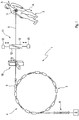
- Fig. 1 is a schematic diagram of an irradiation device 1 for irradiating a lying in a target body 2 target volume range 3 is shown.
- the irradiation device 1 is formed in the present embodiment as a synchotron particle accelerator 4 with a known per se structure.
- the synchotron particle accelerator 4 has an ion source 5 in which individual atoms are generated and ionized, thus present as ions.
- Helium ions, protons, neon ions and, in particular, carbon ions have proven particularly advantageous and effective for medical purposes.
- a major advantage of the particle types mentioned is, in particular, that they - especially carbon - are biocompatible, and therefore do not produce any tissue incompatibility when implanted in a living organic tissue.
- an advantage of said particles is that their energy deposition in the tissue has a relatively sharply pronounced Bragg peak.
- the penetration depth of the particle beam into matter, in particular in the tissue can thus be controlled (and thus, in particular, the region of greatest energy release controllable, for example to treat a tumor in the interior of a body).
- other particles or particles such as protons, electrons and pions and / or also quite generally leptons and hadrons (wherein the irradiation device 1 is to be modified if necessary).
- the particles released by the ion source 5 are first pre-accelerated in a linear accelerator 6 before being injected into the actual accelerator ring 7 of the synchotron particle accelerator 4.
- the particles located in the accelerator ring 7 are then accelerated to the desired energy.
- the accelerator ring 7 acts as a storage ring and the high-energy particles are slowly removed from the accelerator ring 7 via an extraction septum 8, typically extracted (typical extraction times ranging from a few seconds to decade-seconds).
- the extracted particle beam 9 is deflected in a direction laterally to the particle beam direction 9 with the aid of a deflection device 10, which in the present case is in the form of two magnet coil pairs arranged perpendicular to one another.
- an arbitrary point in an x-y plane (is substantially perpendicular to the particle beam 9) can be achieved in the region of the target body 2 (wherein the maximum size of the x-y plane is determined by the precise construction of the irradiation device 1).
- the target volume range 3 in the target body 2 can be successively "approached” with a scan method.
- individual volume units or volume areas in the target volume range 3, generally referred to as raster points can be targeted and successively approached.
- the iso-energy plane lies substantially perpendicular to the direction of the particle beam 9.
- the depth of the iso-energy plane essentially corresponds to the position of the Bragg peaks.
- synchrotron particle accelerators 4 can best compromise particle energy two consecutive extraction cycles vary. For the treatment of a patient, this would result in unreasonably long treatment times.
- a passive energy modulator 11 is used in the present example.
- the passive energy modulator 11 consists of two substantially identical to each other, but symmetrically arranged wedges 12 made of an energy absorbing material.
- the wedges 12 are displaceable, for example, by means of positioning motors 13 (for example linear motors) in a direction substantially perpendicular to the direction of the particle beam 9 (indicated in each case by a double arrow).
- the movements of the two wedges 12 are synchronized with each other.
- the particle beam 9 has to pass through the energy-absorbing material of the two wedges 12 by a different length.
- the energy of the particles of the particle beam 9 is correspondingly greatly reduced.
- the energy of the particles arriving at the actual target body 2 is variable, so that the Bragg peak shifts and thus the target volume 3 can also be scanned in the z-direction.
- the scanning method used today is often a so-called raster scanning method in which the target volume to be irradiated or the target volume range 3 (usually also part of the target volume 3 surrounding tissue of the target body 2) is divided into a larger number of small volume units, so-called raster points.
- the particle beam 9 moves in succession to each individual grid point. Taking into account the extracted intensity, it is ensured via appropriate detectors and the residence time of the particle beam 9 at the individual grid points that the dose optimized in the irradiation planning deposited in the grid point. The implications of such variations in intensity are explained in more detail below.
- the intensity fluctuations are due to the so-called "extraction spectrum".
- the accelerator devices such as, for example, the irradiation device 1
- the extraction spectrum although not constant per se - changes only relatively slowly during the operation of the irradiation device 1.
- the extraction spectrum is measured, for example, at the beginning of a treatment day, or at the beginning of a single treatment, and the extraction spectrum thus measured is used as the basis for the further calculations.
- a planned treatment (see the following description) is introduced in advance into an empty cavity or into a phantom or a dummy. This makes it possible, in particular, to determine the later, temporal course of the treatment at least approximately beforehand.
- a so-called treatment planning is typically created in advance.
- a control data set for the irradiation device 1 is optimized.
- the irradiation planning is performed by calculating which biological effect a particle beam 9 radiates from one or more directions with a particular (three-dimensional) movement pattern (Scanning method) is introduced into the target volume region 3 of the target body 2 caused.
- the calculated biological effects are compared with the biologically effective dose distribution prescribed by the physician. Optimization techniques attempt to minimize the difference between the prescribed dose distribution and the calculated biological effects. It has proven useful to direct the particle beam 9 from two different (in particular opposite) directions in time to the target volume region 3 of the target body 2.
- Fig. 1 An additional problem arises when the target body 2 and / or the target volume region 3 located in the target body 2 moves. This is in Fig. 1 indicated by arrows A.
- the shape of the arrows A is intended to indicate that the movement of the target volume range 3 is not necessarily limited to a linear movement. Rather, the movement can take place along an irregularly shaped curve. It can not only come to movements in the form of translational degrees of freedom, but also it can still be rotational movements, as well as density changes in the tissues involved (especially the latter can lead to a stronger and / or weaker absorption of the particle beam 9, so that the Position of the Bragg peak - and thus the iso-energy plane - shifts).
- Such a movement of the target volume range 3 may arise, for example, when a tumor is to be treated, which is located in or near the lung (respiratory movement), located in or near the heart (heartbeat) or in the area of Intestine is located (intestinal peristalsis).
- the movement of the target volume region 3, in particular the course of its movement is examined in advance.
- imaging methods such as a so-called 4-D CT method (CT for computed tomography) can be used for this purpose.
- CT procedures are rather undesirable, because they bring with them an additional (unwanted) radiation exposure and, moreover, are relatively slow. Therefore, during the measurement of the target volume range movement 3, a substitute signal is typically recorded simultaneously. This may be, for example, a video recording of the corresponding body region, the movement of implanted sensors or strain gauges or the like. If the correlation between the substitute signal and the actual movement of the target volume range 3 has been determined, the position of the target volume range 3 can also be determined with fairly good accuracy on the basis of the substitute motion signal alone.
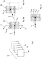
- Irradiation planning now takes place in that instead of a single planning data record 14 (see Fig. 2 ), a plurality of different scheduling records 14a, 14b, 14c ... is used.
- Each planning data record 14a, 14b, 14c ... stands for a specific movement phase of the target volume area 3.
- a typical number of planning data records 14a, 14b, 14c ... is ten planning data records 14a, 14b, 14c ...
- the corresponding, suitable planning data record 14a, 14b, 14c ... is then used, based on the substitute motion signal (or another signal which describes the position of the target volume range 3). If the target volume range 3 has moved sufficiently far, then the next, suitable planning data record 14a, 14b, 14c ... is changed.
- the correction vector which transforms the "output" of the irradiation planning 14a, 14b, 14c ... to the control input of the irradiation device 1, depends on several parameters.
- a first parameter is the speed of movement of the target volume region 3 or of a material section 16 with respect to the outer spatial coordinates. This is in Fig. 3 (especially in Fig. 3a and Fig. 3b ).
- Fig. 3 shows a material section 16, wherein in Fig. 3a and Fig. 3b different temporal snapshots are shown.
- the target volume range 3 (and thus the material cutout 16a) is located in an in Fig. 3a indicated by arrows B movement. After a certain period of time, therefore, the material cutout 16b (see Fig. 3b ) is shifted from the original position 16a. In reality, of course, it is a three-dimensional arrangement of halftone dots. In Fig. 3 For reasons of illustration, a merely two-dimensional target area is shown.
- the corresponding "sheet" 14a, 14b, 14c ... of the overall irradiation plan 15 is selected.
- This sheet represents a kind of precalculated "look up" table containing the control parameters with which the irradiation device 1 (or parts thereof) is driven.
- the deflection device 10 as well as the energy modulator 11 should be mentioned here.
- the target volume range 3 has moved further. So if at a later time t 1 (see Fig. 3b ) the grid point V i, j is actually to be irradiated, the "actually to be irradiated grid point" has already moved on. Falsely, the halftone dot V i-1, j-3 would now be irradiated. If at time t 1 ( Fig. 3b ) the "correct grid point" are irradiated, the particle beam must now irradiate the grid point V i + 1, j + 3 .
- a second parameter represents the time delay which lies between the control input and the conversion of the control input by the acceleration device 1.
- the time delay may well be different in different directions.
- the movement B of the material section 16 in Fig. 3 into a component of motion longitudinal to the particle beam 9, and into a component of motion lateral to the particle beam 9.
- the component of motion lateral to the particle beam 9 can be compensated or compensated by a corresponding suitable control of the deflection device 10.
- a control input can be implemented relatively quickly.
- the delay induced by the deflector 10 is typically in the range of 1 ms.
- time delays usually remain relatively constant during the course of irradiation, they can certainly change between two different irradiations (for example because a larger target volume range 3 must be irradiated, so that a larger number of grid points are used which can lead to a correspondingly more complex calculation.
- a third parameter for the direction and size of the correction corrector is also the actual particle flux (irradiation intensity) provided by the irradiation device 1.
- irradiation intensity the actual particle flux provided by the irradiation device 1.
- the grid point V i, j + 3 is irradiated at the time t 1 .
- the particle flux is not constant, but varies over the course of an extraction cycle. If the particle flux is, for example, greater than ⁇ 1 , the number of particles to be introduced into the respective grid point is faster achieved and the scan progress accordingly faster. This has the consequence that the irradiation of the halftone dot V i, j + 3 already takes place at a time t 1 ', which lies before the time t 1 . With a low particle flow, the scan progress is correspondingly slower. This effect also requires a correction in the form of a correspondingly adapted correction vector.
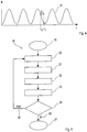
- a respiratory movement curve 17 is shown.
- the typical "average" respiratory movement curve and the actual respiratory movement curve.
- the nutritional value determined thereby is typically sufficiently accurate for practical purposes.
- the actual respiration movement curve deviates very much from the typical value (for example because the patient is coughing)
- the determination of the target point to be controlled in order to irradiate the target volume range 3 in the target body 2 is then carried out by a convolution of the irradiation planning 14a, 14b, 14c ... to be expected for the actual irradiation time and of the correction vector described above. Since the calculation of the correction vector is usually too complex to be carried out online, it is proposed according to a preferred embodiment to calculate a correction value to be applied for all realistically possible parameter combinations of the irradiation device 1 and store it in a correction matrix of suitable size and dimension. During the irradiation, the correction vector can then be read out of the matrix.
- irradiation method 18 is again shown in the form of a schematic flow diagram.
- the irradiation device 1 is initialized and the overall irradiation planning 15 is initialized in the control computer (in FIG Fig. 1 not shown) of the irradiation device 1 is read. This may include in particular the determination of the current extraction profile of the accelerator device 1.
- a first step 20 of the irradiation process 18 the respectively next point to be irradiated (or at the beginning of the method the first point to be irradiated) using the respective planning data set 14a, 14b, 14c ... of the total irradiation planning 15 and the correction vector to be applied.
- a control signal is generated 21, which has suitable values for controlling the irradiation device 1. For example, these are the target current strengths for the deflection device 10 and the target positions for the energy modulator 11.
- the thus determined 21 control signals the individual machine components are driven accordingly 22. With the appropriately equipped irradiation device 1 thus takes place the irradiation 23 of the corresponding halftone dot.
- step 24 it is checked in step 24 whether the irradiation planning has already been completely implemented (branch 25) or whether further points are to be irradiated (branch 26). If it is determined in the checking step 26 that the irradiation has already been completely carried out 25, then the irradiation method 18 is terminated in method step 27. If, on the other hand, it is determined that the irradiation process 18 has not yet been completely completed (branch 26), the process jumps back to the beginning and a new point to be irradiated is determined in step 20.
- a new point to be irradiated is determined.
- the irradiation planning 15 determines the point to be irradiated at the current point in time (step 28).
- the current movement phase of the target volume range 3 is detected and determined (possibly also in advance or in parallel with step 28). Based on this, a prediction is made about the expected movement of the target volume range 3. That's it possible to determine the expected position at a later time, in particular at a time which is to determine the expected time delay between application of a control signal and implementation of the control signal in the future.
- step 29 the current particle flux (the current irradiation intensity) is determined. Based on the current and past values of the particle flow, the position in the extraction spectrum is deduced, so that the (near) future particle fluxes can at least be estimated. Based on this, the speed of the scan progress is determined. Taking both influences into account, the correction values to be used (correction vectors) are determined (step 30) and applied to the target values read from the irradiation planning 15. As a result, in step 31, the actual irradiation coordinates to be applied are obtained. These coordinates are now used for the irradiation procedure 18 (FIG. Fig. 5 ) used.
- the invention is defined in the claims.
Landscapes
- Health & Medical Sciences (AREA)
- Engineering & Computer Science (AREA)
- Biomedical Technology (AREA)
- Pathology (AREA)
- Nuclear Medicine, Radiotherapy & Molecular Imaging (AREA)
- Radiology & Medical Imaging (AREA)
- Life Sciences & Earth Sciences (AREA)
- Animal Behavior & Ethology (AREA)
- General Health & Medical Sciences (AREA)
- Public Health (AREA)
- Veterinary Medicine (AREA)
- Radiation-Therapy Devices (AREA)
Claims (12)
- Procédé (18, 20) permettant de faire fonctionner un dispositif d'irradiation (1) en vue de l'irradiation d'au moins une zone de volume cible (3) d'un corps cible (2) non vivant, avec un faisceau de hadrons, la zone de volume cible (3) du corps cible (2) pouvant être modifiée par une entrée de commande (21) d'un ordinateur de commande du dispositif d'irradiation (1),
selon lequel
lors de la génération (20, 21) de l'entrée de commande (21),- une irradiation d'une zone de volume cible, effectuée précédemment, est prise en compte, et- un vecteur de correction est appliqué au moyen de l'ordinateur de commande, sachant que le vecteur de correction dépend des paramètres suivants :selon lequel l'application du vecteur de correction à l'entrée de commande et la commande du faisceau de hadrons au moyen de l'entrée de commande a pour effet que la zone de volume cible est visée par le faisceau de hadrons pour lequel on peut s'attendre à ce que, à l'instant de l'irradiation effective, il se trouve à l'endroit où le rayonnement du dispositif d'irradiation agit effectivement.- flux de particules actuel, et- vitesse du mouvement de la zone de volume cible (3) ou d'une portion de matière (16) par rapport aux coordonnées spatiales extérieures, et- au moins un laps de temps de retard (Δt) qui est compris entre l'entrée de commande et une réaction du dispositif d'irradiation (1) et qui est pris en compte (30) au moins temporairement et/ou localement, et - Procédé (18, 20) selon la revendication 1, caractérisé en ce que l'on prend en compte une pluralité de laps de temps de retard (Δt) dont la longueur est différente et/ou varie au moins temporairement et/ou au moins partiellement.
- Procédé (18, 20) selon la revendication 1 ou 2, selon lequel on prend en compte, lors de la génération de l'entrée de commande, que lorsque le faisceau de hadrons est dirigé sur la zone de volume cible, le laps de temps de retard (Δt) compris entre l'entrée de commande et la réaction du dispositif d'irradiation (1) est différent pour une déviation latérale (x-y) du faisceau de hadrons par rapport à une déviation longitudinale (z).
- Procédé (18, 20) selon une des revendications précédentes, caractérisé en ce que pour une déviation latérale (x-y) du faisceau de hadrons, le laps de temps de retard (Δt) se situe dans une plage inférieure à 250 ms, de préférence dans une plage inférieure à 100 ms, et/ou en ce que pour une déviation longitudinale (z) du faisceau de hadrons, le laps de temps de retard (Δt) se situe dans une plage inférieure à 150 ms, de préférence dans une plage inférieure à 80 ms.
- Procédé (18, 20) selon une des revendications précédentes, caractérisé en ce qu'au moins un laps de temps de retard (Δt) prend en compte des effets de traitement de signaux et/ou des effets de transmission de signaux.
- Procédé (18, 20) selon une des revendications précédentes, caractérisé en ce que l'on utilise au moins temporairement et/ou au moins localement un algorithme de prédiction temporelle (17), sachant que l'on utilise l'algorithme de prédiction temporelle pour faire une prédiction, sur la base du mouvement actuel du corps cible et/ou de la zone de volume cible, concernant la suite du mouvement du corps cible et/ou de la zone de volume cible,
sachant que l'algorithme de prédiction temporelle peut être exécuté par extrapolation linéaire, extrapolation cubique, extrapolation de splines, par des réseaux neuronaux ou par des chaînes de Markov. - Procédé (18, 20) selon une des revendications précédentes, caractérisé en ce que l'irradiation est réalisée au moins partiellement et/ou au moins localement comme procédé de balayage ou comme procédé de balayage trame (18), ou bien comme procédé de balayage trame (18) à commandé d'intensité.
- Procédé (18, 20) selon une des revendications précédentes, caractérisé en ce que la génération de l'entrée de commande (21) est réalisée au moins temporairement et/ou au moins partiellement en utilisant un plan d'irradiation (14, 15), en particulier au moins temporairement et/ou au moins partiellement en utilisant un plan d'irradiation (14, 15) établi préalablement et/ou établi au cours de l'irradiation et/ou adapté.
- Dispositif d'irradiation (1) destiné à l'irradiation d'au moine une zone de volume cible (3) d'un corps cible (2) avec un faisceau de hadrons, comprenant un ordinateur de commande destiné à fournir une entrée de commande (21) permettant de modifier la zone de volume cible (3) du corps cible (2) devant être irradiée,
dans lequel- une irradiation d'une zone de volume cible, effectuée précédemment, est prise en compte lors de la génération (20, 21) de l'entrée de commande (21),- un vecteur de correction est utilisé lors de la génération (20, 21) de l'entrée de commande (21) au moyen de l'ordinateur de commande, etdans lequel le vecteur de correction dépend des paramètres suivants :- flux de particules actuel, et- vitesse du mouvement de la zone de volume cible (3) ou d'une portion de matière (16) par rapport aux coordonnées spatiales extérieures, et- au moins un laps de temps de retard (Δt) qui est compris entre l'entrée de commande et une réaction du dispositif d'irradiation (1) et qui est pris en compte (30) au moins temporairement et/ou localement,sachant que l'application du vecteur de correction à l'entrée de commande et la commande du faisceau de hadrons au moyen de l'entrée de commande a pour effet que la zone de volume cible est visée, pour laquelle on peut s'attendre à ce que, à l'instant de l'irradiation effective, elle se trouve à l'endroit où le rayonnement du dispositif d'irradiation agit effectivement. - Dispositif d'irradiation (1) selon la revendication précédente, dans lequel, lors de la génération de l'entrée de commande, on prend en compte une pluralité de laps de temps de retard (Δt) dont la longueur est différente et/ou varie au moins temporairement et/ou au moins partiellement.
- Dispositif d'irradiation (1) selon une des revendications 10 ou 11, comprenant en outre un dispositif de déviation (10) destiné à dévier le faisceau de hadrons dans la direction latérale et/ou longitudinale, sachant que l'on prend en compte, au moyen de l'ordinateur de commande, lorsque le faisceau de hadrons est dirigé sur la zone de volume cible, que le laps de temps de retard (Δt) compris entre l'entrée de commande et la réaction du dispositif d'irradiation (1) est différent pour une déviation latérale (x-y) du faisceau de hadrons par rapport à une déviation longitudinale (z).
- Dispositif d'irradiation (1) selon une des revendications 10 à 13, comprenant en outre au moins un dispositif d'adaptation d'irradiation (10, 11) ainsi qu'au moins un dispositif de commande qui est destiné à commander le faisceau de hadrons et qui est réalisé et conçu de manière à mettre en oeuvre, au moyen du dispositif d'adaptation d'irradiation (10, 11), un procédé (18, 20) selon une des revendications 1 à 9.
Applications Claiming Priority (3)
| Application Number | Priority Date | Filing Date | Title |
|---|---|---|---|
| DE102010012654A DE102010012654A1 (de) | 2010-03-25 | 2010-03-25 | Verfahren zum Betreiben einer Bestrahlungsvorrichtung |
| DE102010021119A DE102010021119A1 (de) | 2010-05-20 | 2010-05-20 | Verfahren zum Betreiben einer Bestrahlungsvorrichtung |
| PCT/EP2011/001266 WO2011116889A1 (fr) | 2010-03-25 | 2011-03-15 | Procédés pour faire fonctionner un dispositif d'irradiation |
Publications (2)
| Publication Number | Publication Date |
|---|---|
| EP2550062A1 EP2550062A1 (fr) | 2013-01-30 |
| EP2550062B1 true EP2550062B1 (fr) | 2018-05-16 |
Family
ID=43920959
Family Applications (1)
| Application Number | Title | Priority Date | Filing Date |
|---|---|---|---|
| EP11710690.6A Not-in-force EP2550062B1 (fr) | 2010-03-25 | 2011-03-15 | Procédés pour faire fonctionner un dispositif d'irradiation |
Country Status (2)
| Country | Link |
|---|---|
| EP (1) | EP2550062B1 (fr) |
| WO (1) | WO2011116889A1 (fr) |
Families Citing this family (1)
| Publication number | Priority date | Publication date | Assignee | Title |
|---|---|---|---|---|
| CN115591136B (zh) * | 2022-10-25 | 2025-11-18 | 中国原子能科学研究院 | 一种质子束能量选择控制系统 |
Family Cites Families (3)
| Publication number | Priority date | Publication date | Assignee | Title |
|---|---|---|---|---|
| EP2030650B1 (fr) * | 2003-05-13 | 2011-11-30 | Hitachi, Ltd. | Unité de programmation de traitement utilisant un appareil d'irradiation à faisceau de particules |
| JP3806723B2 (ja) * | 2004-11-16 | 2006-08-09 | 株式会社日立製作所 | 粒子線照射システム |
| US7469035B2 (en) * | 2006-12-11 | 2008-12-23 | The Board Of Trustees Of The Leland Stanford Junior University | Method to track three-dimensional target motion with a dynamical multi-leaf collimator |
-
2011
- 2011-03-15 WO PCT/EP2011/001266 patent/WO2011116889A1/fr not_active Ceased
- 2011-03-15 EP EP11710690.6A patent/EP2550062B1/fr not_active Not-in-force
Non-Patent Citations (1)
| Title |
|---|
| BERT CHRISTOPH ET AL: "4D treatment planning for scanned ion beams", RADIATION ONCOLOGY, BIOMED CENTRAL LTD, LO, vol. 2, no. 1, 3 July 2007 (2007-07-03), pages 24, XP021030775, ISSN: 1748-717X, DOI: 10.1186/1748-717X-2-24 * |
Also Published As
| Publication number | Publication date |
|---|---|
| WO2011116889A1 (fr) | 2011-09-29 |
| EP2550062A1 (fr) | 2013-01-30 |
Similar Documents
| Publication | Publication Date | Title |
|---|---|---|
| DE102007014715B4 (de) | Bestimmung von Steuerparametern für eine Bestrahlung eines bewegten Zielvolumens in einem Körper | |
| DE102008009765B4 (de) | Bestimmen von Steuerparametern einer Bestrahlungsanlage für eine Bestrahlung eines Zielvolumens | |
| DE102007045879B4 (de) | Bestrahlung eines bewegten Zielvolumens | |
| EP2504061B1 (fr) | Procédé et dispositif pour commander l'application de dose lors de l'irradiation | |
| EP2022534B1 (fr) | Dispositif de commande destiné à commander un processus de rayonnement, installation de thérapie à particules ainsi que procédé de rayonnement d'un volume cible | |
| DE102007014394A1 (de) | Bestimmung eines Planungsvolumens für eine Bestrahlung eines Körpers | |
| EP2506929B1 (fr) | Dispositif d'irradiation | |
| EP2648805B1 (fr) | Fantôme d'irradiation | |
| EP1905481B1 (fr) | Installation de thérapie à particules pour la thérapie à particule d'un volume cible soumis à un mouvement | |
| DE102008053611A1 (de) | Bestrahlung eines Zielvolumens unter Berücksichtigung eines zu schützenden Volumens | |
| EP2790784B1 (fr) | Procédé et appareil permettant d'établir un plan d'exposition à un rayonnement pour un volume cible se déplaçant, sans compensation du déplacement | |
| DE102010048233B4 (de) | Verfahren zur Erstellung einer Bestrahlungsplanung sowie Verfahren zur Applizierung einer ortsaufgelösten Strahlendosis | |
| DE102009040390A1 (de) | Verfahren zur Bestimmung eines Bestrahlungsplans, Bestrahlungsplanungseinrichtung sowie Bestrahlungsanlage | |
| EP2550062B1 (fr) | Procédés pour faire fonctionner un dispositif d'irradiation | |
| DE102011109380B4 (de) | Verbesserter Energiemodulator | |
| DE102010012654A1 (de) | Verfahren zum Betreiben einer Bestrahlungsvorrichtung | |
| DE102010021119A1 (de) | Verfahren zum Betreiben einer Bestrahlungsvorrichtung | |
| EP2543239B1 (fr) | Procédé pour faire fonctionner un dispositif accélérateur de particules et dispositif accélérateur de particules | |
| EP2794006B1 (fr) | Procédé permettant de déterminer une dose introduite dans un objet devant être exposé à un rayonnement | |
| DE102011083195B4 (de) | Verfahren und Vorrichtung zur Optimierung eines Partikelbeschleunigers | |
| DE102011083196B4 (de) | Bestimmung der Bestrahlungsdauer bei einer Partikelbestrahlungsplanung | |
| EP2627411B1 (fr) | Planification d'irradiation au moyen d'un faisceau de particules hétérogène |
Legal Events
| Date | Code | Title | Description |
|---|---|---|---|
| PUAI | Public reference made under article 153(3) epc to a published international application that has entered the european phase |
Free format text: ORIGINAL CODE: 0009012 |
|
| 17P | Request for examination filed |
Effective date: 20121023 |
|
| AK | Designated contracting states |
Kind code of ref document: A1 Designated state(s): AL AT BE BG CH CY CZ DE DK EE ES FI FR GB GR HR HU IE IS IT LI LT LU LV MC MK MT NL NO PL PT RO RS SE SI SK SM TR |
|
| DAX | Request for extension of the european patent (deleted) | ||
| 17Q | First examination report despatched |
Effective date: 20160503 |
|
| STAA | Information on the status of an ep patent application or granted ep patent |
Free format text: STATUS: EXAMINATION IS IN PROGRESS |
|
| GRAP | Despatch of communication of intention to grant a patent |
Free format text: ORIGINAL CODE: EPIDOSNIGR1 |
|
| STAA | Information on the status of an ep patent application or granted ep patent |
Free format text: STATUS: GRANT OF PATENT IS INTENDED |
|
| INTG | Intention to grant announced |
Effective date: 20171213 |
|
| GRAS | Grant fee paid |
Free format text: ORIGINAL CODE: EPIDOSNIGR3 |
|
| GRAA | (expected) grant |
Free format text: ORIGINAL CODE: 0009210 |
|
| STAA | Information on the status of an ep patent application or granted ep patent |
Free format text: STATUS: THE PATENT HAS BEEN GRANTED |
|
| AK | Designated contracting states |
Kind code of ref document: B1 Designated state(s): AL AT BE BG CH CY CZ DE DK EE ES FI FR GB GR HR HU IE IS IT LI LT LU LV MC MK MT NL NO PL PT RO RS SE SI SK SM TR |
|
| REG | Reference to a national code |
Ref country code: GB Ref legal event code: FG4D Free format text: NOT ENGLISH |
|
| REG | Reference to a national code |
Ref country code: CH Ref legal event code: EP |
|
| REG | Reference to a national code |
Ref country code: DE Ref legal event code: R096 Ref document number: 502011014188 Country of ref document: DE |
|
| REG | Reference to a national code |
Ref country code: IE Ref legal event code: FG4D Free format text: LANGUAGE OF EP DOCUMENT: GERMAN |
|
| REG | Reference to a national code |
Ref country code: AT Ref legal event code: REF Ref document number: 999000 Country of ref document: AT Kind code of ref document: T Effective date: 20180615 |
|
| REG | Reference to a national code |
Ref country code: NL Ref legal event code: MP Effective date: 20180516 |
|
| REG | Reference to a national code |
Ref country code: LT Ref legal event code: MG4D |
|
| PG25 | Lapsed in a contracting state [announced via postgrant information from national office to epo] |
Ref country code: FI Free format text: LAPSE BECAUSE OF FAILURE TO SUBMIT A TRANSLATION OF THE DESCRIPTION OR TO PAY THE FEE WITHIN THE PRESCRIBED TIME-LIMIT Effective date: 20180516 Ref country code: NO Free format text: LAPSE BECAUSE OF FAILURE TO SUBMIT A TRANSLATION OF THE DESCRIPTION OR TO PAY THE FEE WITHIN THE PRESCRIBED TIME-LIMIT Effective date: 20180816 Ref country code: BG Free format text: LAPSE BECAUSE OF FAILURE TO SUBMIT A TRANSLATION OF THE DESCRIPTION OR TO PAY THE FEE WITHIN THE PRESCRIBED TIME-LIMIT Effective date: 20180816 Ref country code: LT Free format text: LAPSE BECAUSE OF FAILURE TO SUBMIT A TRANSLATION OF THE DESCRIPTION OR TO PAY THE FEE WITHIN THE PRESCRIBED TIME-LIMIT Effective date: 20180516 Ref country code: ES Free format text: LAPSE BECAUSE OF FAILURE TO SUBMIT A TRANSLATION OF THE DESCRIPTION OR TO PAY THE FEE WITHIN THE PRESCRIBED TIME-LIMIT Effective date: 20180516 Ref country code: SE Free format text: LAPSE BECAUSE OF FAILURE TO SUBMIT A TRANSLATION OF THE DESCRIPTION OR TO PAY THE FEE WITHIN THE PRESCRIBED TIME-LIMIT Effective date: 20180516 |
|
| PG25 | Lapsed in a contracting state [announced via postgrant information from national office to epo] |
Ref country code: LV Free format text: LAPSE BECAUSE OF FAILURE TO SUBMIT A TRANSLATION OF THE DESCRIPTION OR TO PAY THE FEE WITHIN THE PRESCRIBED TIME-LIMIT Effective date: 20180516 Ref country code: RS Free format text: LAPSE BECAUSE OF FAILURE TO SUBMIT A TRANSLATION OF THE DESCRIPTION OR TO PAY THE FEE WITHIN THE PRESCRIBED TIME-LIMIT Effective date: 20180516 Ref country code: GR Free format text: LAPSE BECAUSE OF FAILURE TO SUBMIT A TRANSLATION OF THE DESCRIPTION OR TO PAY THE FEE WITHIN THE PRESCRIBED TIME-LIMIT Effective date: 20180817 Ref country code: HR Free format text: LAPSE BECAUSE OF FAILURE TO SUBMIT A TRANSLATION OF THE DESCRIPTION OR TO PAY THE FEE WITHIN THE PRESCRIBED TIME-LIMIT Effective date: 20180516 Ref country code: NL Free format text: LAPSE BECAUSE OF FAILURE TO SUBMIT A TRANSLATION OF THE DESCRIPTION OR TO PAY THE FEE WITHIN THE PRESCRIBED TIME-LIMIT Effective date: 20180516 |
|
| PG25 | Lapsed in a contracting state [announced via postgrant information from national office to epo] |
Ref country code: DK Free format text: LAPSE BECAUSE OF FAILURE TO SUBMIT A TRANSLATION OF THE DESCRIPTION OR TO PAY THE FEE WITHIN THE PRESCRIBED TIME-LIMIT Effective date: 20180516 Ref country code: PL Free format text: LAPSE BECAUSE OF FAILURE TO SUBMIT A TRANSLATION OF THE DESCRIPTION OR TO PAY THE FEE WITHIN THE PRESCRIBED TIME-LIMIT Effective date: 20180516 Ref country code: SK Free format text: LAPSE BECAUSE OF FAILURE TO SUBMIT A TRANSLATION OF THE DESCRIPTION OR TO PAY THE FEE WITHIN THE PRESCRIBED TIME-LIMIT Effective date: 20180516 Ref country code: CZ Free format text: LAPSE BECAUSE OF FAILURE TO SUBMIT A TRANSLATION OF THE DESCRIPTION OR TO PAY THE FEE WITHIN THE PRESCRIBED TIME-LIMIT Effective date: 20180516 Ref country code: RO Free format text: LAPSE BECAUSE OF FAILURE TO SUBMIT A TRANSLATION OF THE DESCRIPTION OR TO PAY THE FEE WITHIN THE PRESCRIBED TIME-LIMIT Effective date: 20180516 Ref country code: EE Free format text: LAPSE BECAUSE OF FAILURE TO SUBMIT A TRANSLATION OF THE DESCRIPTION OR TO PAY THE FEE WITHIN THE PRESCRIBED TIME-LIMIT Effective date: 20180516 |
|
| REG | Reference to a national code |
Ref country code: DE Ref legal event code: R097 Ref document number: 502011014188 Country of ref document: DE |
|
| PG25 | Lapsed in a contracting state [announced via postgrant information from national office to epo] |
Ref country code: IT Free format text: LAPSE BECAUSE OF FAILURE TO SUBMIT A TRANSLATION OF THE DESCRIPTION OR TO PAY THE FEE WITHIN THE PRESCRIBED TIME-LIMIT Effective date: 20180516 Ref country code: SM Free format text: LAPSE BECAUSE OF FAILURE TO SUBMIT A TRANSLATION OF THE DESCRIPTION OR TO PAY THE FEE WITHIN THE PRESCRIBED TIME-LIMIT Effective date: 20180516 |
|
| PLBE | No opposition filed within time limit |
Free format text: ORIGINAL CODE: 0009261 |
|
| STAA | Information on the status of an ep patent application or granted ep patent |
Free format text: STATUS: NO OPPOSITION FILED WITHIN TIME LIMIT |
|
| 26N | No opposition filed |
Effective date: 20190219 |
|
| PG25 | Lapsed in a contracting state [announced via postgrant information from national office to epo] |
Ref country code: SI Free format text: LAPSE BECAUSE OF FAILURE TO SUBMIT A TRANSLATION OF THE DESCRIPTION OR TO PAY THE FEE WITHIN THE PRESCRIBED TIME-LIMIT Effective date: 20180516 |
|
| PG25 | Lapsed in a contracting state [announced via postgrant information from national office to epo] |
Ref country code: MC Free format text: LAPSE BECAUSE OF FAILURE TO SUBMIT A TRANSLATION OF THE DESCRIPTION OR TO PAY THE FEE WITHIN THE PRESCRIBED TIME-LIMIT Effective date: 20180516 |
|
| REG | Reference to a national code |
Ref country code: CH Ref legal event code: PL |
|
| GBPC | Gb: european patent ceased through non-payment of renewal fee |
Effective date: 20190315 |
|
| PG25 | Lapsed in a contracting state [announced via postgrant information from national office to epo] |
Ref country code: LU Free format text: LAPSE BECAUSE OF NON-PAYMENT OF DUE FEES Effective date: 20190315 Ref country code: AL Free format text: LAPSE BECAUSE OF FAILURE TO SUBMIT A TRANSLATION OF THE DESCRIPTION OR TO PAY THE FEE WITHIN THE PRESCRIBED TIME-LIMIT Effective date: 20180516 |
|
| REG | Reference to a national code |
Ref country code: BE Ref legal event code: MM Effective date: 20190331 |
|
| PG25 | Lapsed in a contracting state [announced via postgrant information from national office to epo] |
Ref country code: CH Free format text: LAPSE BECAUSE OF NON-PAYMENT OF DUE FEES Effective date: 20190331 Ref country code: LI Free format text: LAPSE BECAUSE OF NON-PAYMENT OF DUE FEES Effective date: 20190331 Ref country code: IE Free format text: LAPSE BECAUSE OF NON-PAYMENT OF DUE FEES Effective date: 20190315 Ref country code: GB Free format text: LAPSE BECAUSE OF NON-PAYMENT OF DUE FEES Effective date: 20190315 |
|
| PG25 | Lapsed in a contracting state [announced via postgrant information from national office to epo] |
Ref country code: FR Free format text: LAPSE BECAUSE OF NON-PAYMENT OF DUE FEES Effective date: 20190331 Ref country code: BE Free format text: LAPSE BECAUSE OF NON-PAYMENT OF DUE FEES Effective date: 20190331 |
|
| PG25 | Lapsed in a contracting state [announced via postgrant information from national office to epo] |
Ref country code: TR Free format text: LAPSE BECAUSE OF FAILURE TO SUBMIT A TRANSLATION OF THE DESCRIPTION OR TO PAY THE FEE WITHIN THE PRESCRIBED TIME-LIMIT Effective date: 20180516 |
|
| PG25 | Lapsed in a contracting state [announced via postgrant information from national office to epo] |
Ref country code: PT Free format text: LAPSE BECAUSE OF FAILURE TO SUBMIT A TRANSLATION OF THE DESCRIPTION OR TO PAY THE FEE WITHIN THE PRESCRIBED TIME-LIMIT Effective date: 20180917 Ref country code: MT Free format text: LAPSE BECAUSE OF FAILURE TO SUBMIT A TRANSLATION OF THE DESCRIPTION OR TO PAY THE FEE WITHIN THE PRESCRIBED TIME-LIMIT Effective date: 20180516 |
|
| REG | Reference to a national code |
Ref country code: AT Ref legal event code: MM01 Ref document number: 999000 Country of ref document: AT Kind code of ref document: T Effective date: 20190315 |
|
| PG25 | Lapsed in a contracting state [announced via postgrant information from national office to epo] |
Ref country code: AT Free format text: LAPSE BECAUSE OF NON-PAYMENT OF DUE FEES Effective date: 20190315 |
|
| PG25 | Lapsed in a contracting state [announced via postgrant information from national office to epo] |
Ref country code: CY Free format text: LAPSE BECAUSE OF FAILURE TO SUBMIT A TRANSLATION OF THE DESCRIPTION OR TO PAY THE FEE WITHIN THE PRESCRIBED TIME-LIMIT Effective date: 20180516 |
|
| PG25 | Lapsed in a contracting state [announced via postgrant information from national office to epo] |
Ref country code: IS Free format text: LAPSE BECAUSE OF FAILURE TO SUBMIT A TRANSLATION OF THE DESCRIPTION OR TO PAY THE FEE WITHIN THE PRESCRIBED TIME-LIMIT Effective date: 20180916 |
|
| PG25 | Lapsed in a contracting state [announced via postgrant information from national office to epo] |
Ref country code: HU Free format text: LAPSE BECAUSE OF FAILURE TO SUBMIT A TRANSLATION OF THE DESCRIPTION OR TO PAY THE FEE WITHIN THE PRESCRIBED TIME-LIMIT; INVALID AB INITIO Effective date: 20110315 |
|
| PGFP | Annual fee paid to national office [announced via postgrant information from national office to epo] |
Ref country code: DE Payment date: 20220322 Year of fee payment: 12 |
|
| PG25 | Lapsed in a contracting state [announced via postgrant information from national office to epo] |
Ref country code: MK Free format text: LAPSE BECAUSE OF FAILURE TO SUBMIT A TRANSLATION OF THE DESCRIPTION OR TO PAY THE FEE WITHIN THE PRESCRIBED TIME-LIMIT Effective date: 20180516 |
|
| REG | Reference to a national code |
Ref country code: DE Ref legal event code: R119 Ref document number: 502011014188 Country of ref document: DE |
|
| PG25 | Lapsed in a contracting state [announced via postgrant information from national office to epo] |
Ref country code: DE Free format text: LAPSE BECAUSE OF NON-PAYMENT OF DUE FEES Effective date: 20231003 |